Cognex In-Sight 5110 ユーザーマニュアル

タイプ
ユーザーマニュアル
In-Sight
®
5000 Series
Vision System
Manual
2019 October 02
Revision: 5.8.0.1
Regulations/Conformity
Note: For the most up-to-date regulations and conformity information, please
refer to the Cognexonline support site: http://www.cognex.com/Support.
Safety and Regulatory
In-Sight 5100/5110/5400/5410: Type 821-0034-1R
In-Sight 5100C/5400C: Type 821-0036-1R
In-Sight 5403/5413: Type 821-0037-1R
FCC
FCC Part 15, Class A
This device complies with Part 15 of the FCC Rules. Operation is subject to the
following two conditions: (1) this device may not cause harmful interference; and (2)
this device must accept any interference received, including interference that may
cause undesired operation. This equipment generates, uses, and can radiate radio
frequency energy and, if not installed and used in accordance with the instruction
manual, may cause harmful interference to radio communications. Operation of this
equipment in a residential area is likely to cause harmful interference in which case the
user will be required to correct the interference at their own expense.
KCC In-Sight 5100/5110/5400/5410: CGX-IS5400-01(A)
In-Sight 5100C/5400C: CGX-IS5400-C01(A)
In-Sight 5403/5413: CGX-IS5403-01(A)
NRTL V SÜD AM SCC/NRTL OSHA Scheme for UL/CAN 60950-1.
CB V SÜD AM, IEC/EN 60950-1. CB report available upon request.
RoHS Compliant to the latest applicable Directive.
1
Safety and Regulatory
In-Sight 5600/5610: Type 821-0041-1R
In-Sight 5603/5613: Type 821-0042-1R
In-Sight 5604/5614: Type 821-0051-1R
In-Sight 5605/5615: Type 821-0032-1R; Type 821-0032-2R
In-Sight 5705/5715/5705C: Regulatory Model 1AAF
FCC
FCC Part 15, Class A
This device complies with Part 15 of the FCC Rules. Operation is subject to the
following two conditions: (1) this device may not cause harmful interference; and (2)
this device must accept any interference received, including interference that may
cause undesired operation. This equipment generates, uses, and can radiate radio
frequency energy and, if not installed and used in accordance with the instruction
manual, may cause harmful interference to radio communications. Operation of this
equipment in a residential area is likely to cause harmful interference in which case the
user will be required to correct the interference at their own expense.
KCC In-Sight 5600/5610: KCC-REM-CGX-IS5600-01
In-Sight 5603/5613: KCC-REM-CGX-IS5603-01
In-Sight 5604/5614: KCC-REM-CGX-IS5604-01
In-Sight 5605/5615: CGX-IS5605-01(A)
In-Sight 5705/5715/5705C: Regulatory Model 1AAF: MSIP-REM-CGX-1AAF
NRTL V SÜD AM SCC/NRTL OSHA Scheme for UL/CAN 61010-1.
CB V SÜD AM, IEC/EN 61010-1. CB report available upon request.
RoHS Compliant to the latest applicable Directive.
2
Precautions
Observe these precautions when installing the Cognex product, to reduce the risk of
injury or equipment damage:
l In-Sight 5000 series vision systems are intended to be supplied by a UL or
NRTL listed power supplywith a 24VDC output rated for at least 600 mA
continuousand a maximum short circuit current rating of less than 8A and a
maximum power rating of less than 100VA and marked Class2 or Limited
Power Source (LPS). Any other voltage creates a risk of fire or shock and
can damage the components. Applicable national and local wiring
standards and rules must be followed.
l Do not install In-Sight vision systemswhere they are directly exposed to
environmentalhazardssuch as excessive heat, dust, moisture, humidity,
impact, vibration, corrosive substances, flammable substances, or static
electricity.
l To reduce the risk of damage or malfunction due to over-voltage, line noise,
electrostatic discharge (ESD), power surges, or other irregularities in the
power supply, route all cablesand wires away from high-voltage power
sources.
l The housing of the vision system is internally connected to the system
ground wire (pin 8 of the Breakout cable). Therefore, if the mounting
surface of the vision system is at a non-zero ground potential, it is strongly
recommended that the vision system be mounted on an isolated or non-
conductive mount.
3
l Do not expose the image sensor to laser light; image sensors can be
damaged by direct, or reflected, laser light. If your application requires the
use of laser light that may strike the image sensor, a lens filter at the
corresponding laser's wavelength is recommended. Contact your local
integrator or application engineer for suggestions.
l The In-Sight vision system does not contain user-serviceable parts. Do not
make electrical or mechanical modifications to In-Sight vision system
components. Unauthorized modifications may void your warranty.
l Changes or modificationsnot expressly approved by the party responsible
for regulatory compliance could void the users authority to operate the
equipment.
l Service loops should be included with allcable connections.
l Cable shielding can be degraded or cables can be damaged or wear out
more quickly if a service loop or bend radius is tighter than 10X the cable
diameter. The bend radius must be at least six inches from the connector.
l Class A Equipment (broadcasting and communication equipment for office
work): Seller and user shall be notified that thisequipment is suitable for
electromagnetic equipment for office work (Class A) and can be used
outside the home.
l This device should be used in accordance with the instructions in this
manual.
4
5
Installation
Installation procedures and specifications are presented in detail in the In-Sight
®
5000 Series Vision System Reference Guide, which is installed with In-Sight Explorer
software. From the Windows Start menu, select the following to access the manual:
All Programs > Cognex > In-Sight > In-Sight Explorer x.x.x > Documentation.
Note:
l Cables are sold separately.
l If any of the standard components appear to be missing or damaged,
immediately contact your Cognex Authorized Service Provider (ASP)
or Cognex Technical Support.
CAUTION: All cable connectors are “keyed” to fit the connectors on the vision
system; do not force the connections or damage may occur.
Install the Lens
1. Remove the protective film covering the threaded lens opening, if present.
2. Attach a C-Mount lens to the vision system. The exact lens focal length
needed depends on the working distance and the field of view required for
your machine vision application.
3. If using a lens cover, remove the thread guard and attach the lens to the
vision system.
6
Connect the Ethernet Cable
1. Connect the Ethernet cable’s M12 connector to the vision systems ENET
connector.
2. Connect the Ethernet cable’s RJ-45 connector to a switch/router or PC, as
applicable.
Connect the Breakout Cable
Note: Unused bare wires can be clipped short or tied back using a tie made of
non-conductive material. Keep all bare wires separated from the +24VDC
wire.
1. Verify that the 24VDC power supply being used is unplugged and not
receiving power.
2. Optionally, connect the I/O or serial wires to an appropriate device (for
example, a PLC, an encoder, or a serialdevice).
Note: When using an In-Sight 5604 line scan vision system, the RS-
232RX wire is used as Encoder A and the RS-232TX wire is used as
Encoder B.
3. Attach the I/O Breakout cable's +24VDC (White/Green wire) and 24V
COMMON (Brown wire) to the corresponding terminalson the power
supply.
CAUTION: Never connect voltages other than 24VDC. Always
observe the polarity shown.
7
4. Attach the Breakout cable's M12 connector to the vision system's 24VDC
connector.
5. Restore power to the 24VDC power supply and turn it on if necessary.
Install Software and Documentation
To configure an In-Sight vision system, In-Sight Explorer software must be installed
on a networked PC. In-Sight software is available as a free download from the In-
Sight support site, or can be purchased separately on a DVD.
Log On to the Vision System
1. Open the In-Sight Explorer software. From the Windows Start menu,
select: All Programs > Cognex > In-Sight > In-Sight Explorer x.x.x > In-Sight
Explorer x.x.x.
2. From the Get Connected Application Step, select your In-Sight vision
system from the Select an In-Sight Sensor or Emulator group box and press
the Connect button.
8
5100, 5100C, 5400C, 5403 and 5400 Vision
System Specifications
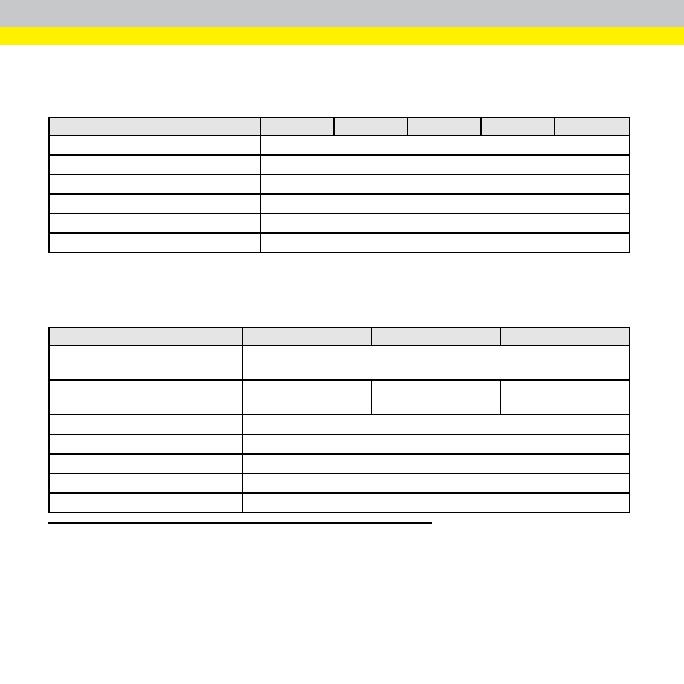
Specification 5100/5110 5100C 5400C 5403/5413 5400/5410
Operating Temperature 0°C to 45°C (32°F to 11F)
Storage Temperature -3C to 8C (-2F to 176°F)
Humidity 95%, non-condensing (Operating and Storage)
Protection IP67 (with appropriate lens cover properly installed).
Shock (Shipping and Storage) 80 G Shock with 150 gram lens attached per IEC 68-2-27.
Vibration (Shipping and Storage) 10 G from 10-500 Hz with 150 gram lens per IEC 68-2-6.
5603, 5600 and 5605 Vision System
Specifications
Specification 5603/5613 5600/5610 5605/5615
Operating Temperature (non-
circulating air)
0°C to 45°C (32°F to 11F)
1
Operating Temperature (circulating
air)
0°C to 50°C (32°F to
122°F)
2
0°C to 50°C (32°F to
122°F)
3
0°C to 50°C (32°F to
122°F)
4
Storage Temperature -3C to 8C (-2F to 17F)
Humidity 95%, non-condensing (Operating and Storage)
Protection IP67 (with appropriate lens cover properly installed).
Shock (Shipping and Storage) 80 G Shock with 150 gram lens attached per IEC 68-2-27.
Vibration (Shipping and Storage) 10 G from 10-500 Hz with 150 gram lens per IEC 68-2-6.
1
The vision system should be mounted with sufficient clearance on allsides to allow air circulation around and through the cooling posts
on the blackheat sink.
2
Additionalcooling from a fan is recommended foroperation above 4C. Foroperation up to 5C, there must be 16 CFM of air
moving through the cooling postson the black heat sink.
3
Additionalcooling from a fan is recommended foroperation above 4C. Foroperation up to 5C, there must be 4 CFM of air
moving through the cooling postson the black heat sink.
4
Additionalcooling from a fan is recommended foroperation above 4C. Foroperation up to 5C, there must be 16 CFM of air
moving through the cooling postson the black heat sink.
9
5604 Line Scan Vision System Specifications
Specification 5604/5614
Operating Temperature (non-circulating air) 0°C to 45°C (32°F to 113°F)
1
Operating Temperature (circulating air) 0°C to 50°C (32°F to 122°F)
2
Storage Temperature -3C to 8C (-2F to 176°F)
Humidity 95%, non-condensing (Operating and Storage)
Protection IP67 (with appropriate lens cover properly installed).
Shock (Shipping and Storage) 80 G Shock with 150 gram lens attached per IEC 68-2-27.
Vibration (Shipping and Storage) 10 G from 10-500 Hz with 150 gram lens per IEC 68-2-6.
5705 and 5705C Vision System
Specifications
Specification 5705/5715 5705C
Operating Temperature (non-circulating air) 0°C to 45°C (32°F to 113°F)
3
Operating Temperature (circulating air) 0°C to 50°C (32°F to 122°F)
4
Storage Temperature -30°C to 80°C (-2F to 176°F)
Humidity 95%, non-condensing (Operating and Storage)
Protection IP67 (with appropriate lens cover properly installed).
Shock (Shipping and Storage) 80 G Shock with 150 gram lens attached per IEC 68-2-27.
Vibration (Shipping and Storage) 10 G from 10-500 Hz with 150 gram lens per IEC 68-2-6.
1
The vision system should be mounted with sufficient clearance on allsides to allow air circulation around and through the cooling posts
on the blackheat sink. If the vision system isnotmounted with sufficient clearance, a fan isrecommended.
2
Additionalcooling from a fan is recommended foroperation above 4C. Foroperation up to 5C, there must be 16 CFM of air
moving through the cooling postson the black heat sink.
3
The vision system should be mounted with sufficient clearance on allsides to allow air circulation around and through the cooling posts
on the blackheat sink.
4
Additionalcooling from a fan is recommended foroperation above 4C. Foroperation up to 5C, there must be 16 CFM of air
moving through the cooling postson the black heat sink.
10
規制報/合宣
: 制および適合宣言に関する最新情報については、Cognex ンラインサ
ポートセンターにアクセスてください。http://www.cognex.com/Support
安全規制
In-Sight 5100/5110/5400/5410: イプ 821-0034-1R
In-Sight 5100C/5400C: イプ 821-0036-1R
In-Sight 5403/5413: イプ 821-0037-1R
FCC
FCC (アメリカ連邦通信委員会) 規則第 15 章クラス A 準拠
本装置は FCC 規則第 15 章に準拠しており、 次の 2 の条件を前提として動作し
す。(1) 本装置が有害な干渉を起こさなこと。(2) 本装置が干渉(誤動作を引き起こ
恐れの干渉を含む) を受けても耐えること。本装置は高周波を発生・使用・放射する
ことります。取扱説明書の指示にしがわに設置・使用し場合、無線通信に有害
干渉を与える可能性がります。本装置を住宅地で使用す有害な電波障害を起こ
す恐れがあり、この場合、使用者の負担で障害を是正する必要があります。
KCC In-Sight 5100/5110/5400/5410: CGX-IS5400-01(A)
In-Sight 5100C/5400C: CGX-IS5400-C01(A)
In-Sight 5403/5413: CGX-IS5403-01(A)
NRTL TÜV SÜD AM SCC/NRTL OSHA Scheme for UL/CAN 60950-1
CB TÜV SÜD AM、IEC/EN 60950-1
請求により、CB 報告書を提供しす。
RoHS 適用可能な最新の指令に準拠。
1
安全規制
In-Sight 5600/5610: イプ 821-0041-1R
In-Sight 5603/5613: イプ 821-0042-1R
In-Sight 5604/5614: イプ 821-0051-1R
In-Sight 5605/5615: イプ 821-0032-1R; イプ 821-0032-2R
In-Sight 5705/5715/5705C: 規制モデル 1AAF
FCC
FCC (アメリカ連邦通信委員会) 規則第 15 章クラス A 準拠
本装置は FCC 規則第 15 章に準拠しており、 次の 2 の条件を前提として動作し
す。(1) 本装置が有害な干渉を起こさなこと。(2) 本装置が干渉(誤動作を引き起こ
恐れの干渉を含む) を受けても耐えること。本装置は高周波を発生・使用・放射する
ことります。取扱説明書の指示にしがわに設置・使用し場合、無線通信に有害
干渉を与える可能性がります。本装置を住宅地で使用す有害な電波障害を起こ
す恐れがあり、この場合、使用者の負担で障害を是正する必要があります。
KCC In-Sight 5600/5610: KCC-REM-CGX-IS5600-01
In-Sight 5603/5613: KCC-REM-CGX-IS5603-01
In-Sight 5604/5614: KCC-REM-CGX-IS5604-01
In-Sight 5605/5615: CGX-IS5605-01(A)
In-Sight 5705/5715/5705C: 規制モデル 1AAF: MSIP-REM-CGX-1AAF
NRTL TÜV SÜD AM SCC/NRTL OSHA Scheme for UL/CAN 61010-1
CB TÜV SÜD AM, IEC/EN 61010-1 請求にり、CB 報告書を提供します。
RoHS 適用可能な最新の指令に準拠。
2
注意
人体の障害や機器の損傷ぐために、Cognex 品をインストールする際に
意事項を厳守してください。
l In-Sight 5000 リーズビョンシステムは、UL または NRTL 格に準拠
た最低定格 24 VDC およ 600mA 、短絡定格電流最大 8A 下、電
力定最大 100VA 下、クラス 2 または LPS (Limited Power Source)
よる電力供給を必要とます。異なる電源を使用すると、火災や感電の危険
コンポーネントに損傷を与える原因となります要に応じて、およ
び地域線規格および規則に従ってください。
l 過度の熱、ほこり、水分湿度、衝撃振動、腐食性物質、可燃性物質、静電
などの境下に、In-Sight ンシステムを設置しないでくだい。
l 過電回線ノイズ、静電気放 (ESD)、電力ージその源異常に
因した損傷や誤作動止するために、ケーブワイヤはすて高電圧電源
を避け線してください。
l ンシテムの筐体、内部でシステムのグンド線 (ークトケー
8 ン) 接続されていますたがって、ビジョンシステ置場
所でラウンドとの電位差が生じる可能性ある場合、設置面を絶縁す
、または非導電性定具使用してください。
l ーザー光線を画像センサ当てないでください。直接的または間接的にレ
ー光線が当たると、画像センサ傷する可能性あります像センサに
ーザー光線たるような場合には、対応するレーザーの波長に合せたレ
ンズフィルタ勧めします近くのシステンテグレータやアプリケーシ
ンエンジニお尋ください。
l In-Sight ョンシステムには、ユーザが理できる部品はありません。電気
または機械的な変造を加えないでください。許可なく造を行った場合は、保
証が無効になります。
3
l 各種格関連団体か示的な了承なし変更造を行った場合は、本
機器の使用権を失う可能性あります。
l ーブルの配線時はサービープ (余長ループ) を設けください
l ーブル径 10 に満たない小さな曲げ半径やサービループを設けた場
ーブルのシールドの化、ケーブ傷または磨耗が短期間で生
ますげ半径コネタか最低 6 インチ離ている必要
l ラス A (商業目的送・通信機器)。本機器は、商用磁機 (ク
ラス A) 庭用以外で使用可能であること、販売者あるいは購入者に
知する必要があります。
l のデバイスは、マニアルの指示にしたがて使用てください
4
5
設置
設置順および仕様についての細は、In-Sight
®
Explorer ソフウェア格納されて
いる、『In-Sight 5000 シリーズビンシテムリファレンスガイド』をご照ください。
のガイドにアクセスするに、ウィンドウズの [スタート] メニューか[すべてのプログラ
] > [Cognex] > [In-Sight] > [In-Sight Explorer x.x.x] > [ドキュメント] を選択してくだ
さい
:
l ーブルは別途ご入ください。
l 内容不足や破損がある場合は、コグック販売代理 (ASP)
たは弊社テクニカルサポートまでご連絡ださい。
注意 : ーブは、ビジョンシステムのコネクー溝に合せて接合するよ
に設計さています理に接ると損するこがあります
レンズの取付け
1. ネジ付きレンズ開口部カバーしている保護フィルムを取ます (保護
ムがない場もあります)
2. ビョンシステムに C ウントレンズを取り付けます ズの焦点距離は、
ンビンアプリケーションがとする視野とワークスタによって変
ります
3. レンズカバーを使用している場合レッドガードを取り外し、ンシステ
にレンズをます。
6
サネッルの接
1. イーサットケーブ M12 コネタをビンシテム ENET コネタに
接続ます
2. イーサットケーブ RJ-45 コネクタを、必要に応イッチ/ータまた
PC に接続します
クアブルの接
: 使用しないワイヤは切断するたは縁材で保護してください。 +24VDC
ワイヤョートするこのないようご意ください。
1. 24VDC 電源イッチ OFF ているこを確認ます
2. I/O またはシリアルワイヤを適切なデバイス (PLCエンコーダ、シリアルデバイ
ど) 接続ます (オプション)。
: In-Sight 5604 ラインスャンビンシステムを使用する場合
RS-232RX ワイヤコーダ A て、RS-232TX ワイヤコー
B て使用ます
3. I/O ークトケーブ +24VDC (色/緑色ワイヤ) よび 24V コモ
(茶色ワイヤ) を電源応する端子に接ます
注意 : 24VDC 以外圧は使用しないでくだい。載さている極
性を遵守してください。
4. ブークトケーブ M12 コネクビジョンシステ 24VDC コネ
タに接続ます
5. 24VDC 電源ます
7
ソフトおよびドキュメントのインスト
In-Sight ョンシステムを設定するには、In-Sight Explorer トウアをトワー
上の PC インストールする必要があります。In-Sight ウェアは、In-Sight
ポートイト無償ダウンロードするか、るいは別売インストール DVD-ROM をご
購入ください。
ジョンシステムのログオ
1. In-Sight Explorer を開きます。Windows [スタート] メニューか[すての
プログラム] > [Cognex] > [In-Sight Explorer x.x.x] > [In-Sight Explorer
x.x.x] を選択します
2. [続] アプリケーションテッで、In-Sight ンシステムを [In-Sight セン
サまたはュレータ] グループボック[続] ボタンを押します。
8
51005100C5400C、5403 およ 5400
ジョンシステムの仕様
仕様 5100/5110 5100C 5400C 5403/5413 5400/5410
動作時の温度 0°C~45°C
保存時の温度 -30~80°C
湿度 95%、結露しないこ (動作および保管)
保護 IP67 (適切なズカバー装着時)
衝撃 (輸送おび保管) IEC 68-2-27 準拠、80 G (150 グラムのレンズ装着時)
振動 (輸送おび保管) IEC 68-2-6 準拠、 10~500 Hz 範囲で 10 G
56035600 およ 5605 ジョンシステムの仕
仕様 5603/5613 5600/5610 5605/5615
動作時の温度 (空気非循環時)
0°C~45°C
1
動作時の温度 (空気循環時)
0°C~50°C
2
0°C~50°C
3
0°C~50°C
4
保存時の温度 -30~80°C
湿度 95%、結露しないこ (動作および保管)
保護 IP67 (適切なズカバー装着時)
衝撃 (保管おび輸送) IEC 68-2-27 準拠、80 G (150 グラムのレンズ装着時)
振動 (輸送おび保管) IEC 68-2-6 準拠、 10~500 Hz 範囲で 10 G
1
ビジョンシステムの設置あたっ、すべて面に十分な隙間を確保し、いヒートシンク体に空気がれるうにしてください
2
動作度が 40°C 超える合は、らにファン冷却必要す。動作時の温度 50°C では、黒いヒートシン却ポスト周囲
16 CFM 以上気のが必要です。
3
動作度が 40°C 超える合は、らにファン冷却必要す。動作時の温度 50°C では、黒いヒートシン却ポスト周囲
4 CFM 上の空気が必要です。
4
動作度が 40°C 超える合は、らにファン冷却必要す。動作時の温度 50°C では、黒いヒートシン却ポスト周囲
16 CFM 以上気のが必要です。
9
  • Page 1 1
  • Page 2 2
  • Page 3 3
  • Page 4 4
  • Page 5 5
  • Page 6 6
  • Page 7 7
  • Page 8 8
  • Page 9 9
  • Page 10 10
  • Page 11 11
  • Page 12 12
  • Page 13 13
  • Page 14 14
  • Page 15 15
  • Page 16 16
  • Page 17 17
  • Page 18 18
  • Page 19 19
  • Page 20 20
  • Page 21 21
  • Page 22 22
  • Page 23 23
  • Page 24 24
  • Page 25 25
  • Page 26 26
  • Page 27 27
  • Page 28 28
  • Page 29 29
  • Page 30 30
  • Page 31 31
  • Page 32 32
  • Page 33 33
  • Page 34 34
  • Page 35 35
  • Page 36 36
  • Page 37 37
  • Page 38 38
  • Page 39 39
  • Page 40 40
  • Page 41 41
  • Page 42 42
  • Page 43 43
  • Page 44 44
  • Page 45 45
  • Page 46 46
  • Page 47 47
  • Page 48 48
  • Page 49 49
  • Page 50 50
  • Page 51 51
  • Page 52 52
  • Page 53 53
  • Page 54 54
  • Page 55 55
  • Page 56 56
  • Page 57 57
  • Page 58 58
  • Page 59 59
  • Page 60 60
  • Page 61 61
  • Page 62 62
  • Page 63 63
  • Page 64 64
  • Page 65 65
  • Page 66 66
  • Page 67 67
  • Page 68 68
  • Page 69 69
  • Page 70 70
  • Page 71 71
  • Page 72 72
  • Page 73 73
  • Page 74 74
  • Page 75 75
  • Page 76 76

Cognex In-Sight 5110 ユーザーマニュアル

タイプ
ユーザーマニュアル