
Sony Corporation Printed in China
(1)
http://www.sony.net/
3-398-069-51(1)
©2008 Sony Corporation
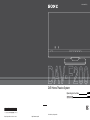
DVD Home Theatre System
GB
CT
Operating Instructions
ợ䒌娎㕲㙜

2
GB
To reduce the risk of fire or electric
shock, do not expose this apparatus to
rain or moisture.
Do not install the appliance in a confined space, such
as a bookcase or built-in cabinet.
To prevent fire, do not cover the ventilation of the
apparatus with news papers, table-cloths, curtains, etc.
And don’t place lighted candles on the apparatus.
To prevent fire or shock hazard, do not place objects
filled with liquids, such as vases, on the apparatus.
Batteries or batteries installed apparatus shall not be
exposed to excessive heat such as sunshine, fire or the
like.
This appliance is
classified as a CLASS 1
LASER product. This
marking is located on the
rear exterior of control
unit.
Precautions
On power sources
• AC power cord (mains lead) must be changed only at
the qualified service shop.
• The system is not disconnected from the AC power
source (mains) as long as the subwoofer is connected
to the wall outlet (mains), even if the control unit
itself has been turned off.
• Install this system so that the AC power cord (mains
lead) can be unplugged from the wall socket
immediately in the event of trouble.
WARNING

3
GB
About This Operating
Instructions
• The instructions in this Operating Instructions
describe the controls on the remote. You can
also use the controls on the control unit if they
have the same or similar names as those on the
remote.
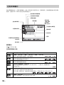
• The Control Menu items may vary depending
on the area.
• “DVD” may be used as a general term for a
DVD VIDEO, DVD+RW/DVD+R, and DVD-
RW/DVD-R.
• The default setting is underlined.
GB

4
GB
Table of Contents
About This Operating Instructions..........3
Playable Discs.........................................5
Getting Started
Step 1: Positioning the System ...11
Step 2: Connecting the System ...15
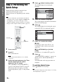
Step 3: Performing the Quick
Setup ........................................26
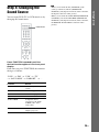
Step 4: Changing the Sound
Source ......................................29
Disc
Playing a Disc .......................................30
Using Play Mode...................................35
Searching/Selecting a Disc ...................38
Playing MP3 Files/JPEG Image Files... 41
Enjoying DivX
®
Videos ....................... 45
Restricting Playback of the Disc........... 47
Sound Adjustment
Enjoying Surround Sound by Using
Decoding Mode ..............................50
Selecting the Sound Mode .................... 52
Enjoying Multiplex Broadcast Sound... 53
Tuner
Presetting Radio Stations ......................54
Listening to the Radio........................... 55
Control for HDMI/External
Audio Device
Using the Control for HDMI Function for
“BRAVIA” Sync ............................ 57
Playing Back Audio Files/JPEG Image
Files of a USB Device .................... 60
Transferring Songs in a USB Device....69
Using the DIGITAL MEDIA PORT
Adapter ........................................... 72
Other Operation
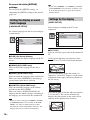
Using the Setup Display........................73
Adjusting the Delay Between the Picture
and Sound ....................................... 79
Changing the Input Level of the
Sound..............................................79
Enjoying the Sound at Low Volume..... 80
Using the Sleep Timer .......................... 80
Changing the Brightness of the Front
Panel Display and Illumination...... 81
Viewing Information About the Disc ... 82
Controlling the TV with the Supplied
Remote ........................................... 85
Returning to the Default Settings ......... 87
Additional Information
Precautions ........................................... 89
Notes about the Discs ........................... 90
Troubleshooting.................................... 91
Self-diagnosis Function ........................ 99
Specifications ..................................... 100
Glossary.............................................. 101
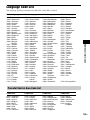
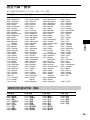
Language Code List............................ 103
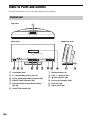
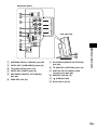
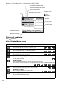
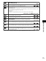
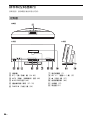
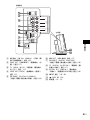
Index to Parts and Control.................. 104
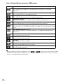
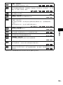
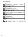
Guide to the Control Menu Display ... 109
Index ................................................... 113

5
GB
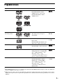
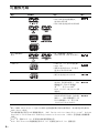
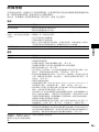
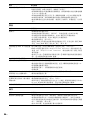
Playable Discs
1)
MP3 (MPEG1 Audio Layer 3) is a standard format defined by ISO/MPEG which compresses audio data. MP3 files
must be in MPEG1 Audio Layer 3 format.
2)
JPEG image files must conform to the DCF image file format. (DCF “Design rule for Camera File system”: Image
standards for digital cameras regulated by Japan Electronics and Information Technology Industries Association
(JEITA).)
Type Disc logo Characteristics Icon
DVD VIDEO • DVD VIDEO
• DVD-R/DVD-RW in DVD
VIDEO format or video mode
• DVD+R/DVD+RW in DVD
VIDEO format
VR (Video
Recording) mode
• DVD-R/DVD-RW in VR (Video
Recording) mode (except for
DVD-R DL)
VIDEO CD • VIDEO CD (Ver. 1.1 and 2.0 discs)
• Super VCD
• CD-R/CD-RW/CD-ROM in video
CD format or Super VCD format
CD • Audio CD
• CD-R/CD-RW in audio CD format
DATA CD – • CD-R/CD-RW/CD-ROM in
DATA CD format, containing MP3
files
1)
, JPEG image files
2)
, and
DivX video files
3)4)
, and
conforming to ISO 9660
5)
Level 1/
Level 2, or Joliet (extended format)
DATA DVD – • DVD-ROM/DVD-R/DVD-RW/
DVD+R/DVD+RW in DATA
DVD format, containing MP3
files
1)
, JPEG
image files
2)
, and
DivX video files
3)4)
, and
conforming to UDF (Universal
Disk Format)

6
GB
3)
DivX
®
is a video file compression technology, developed by DivX, Inc.
4)
DivX, DivX Certified, and associated logos are trademarks of DivX, Inc. and are used under license.
5)
A logical format of files and folders on CD-ROMs, defined by ISO (International Organization for
Standardization).
“DVD-RW,” “DVD+RW,” “DVD+R,”“DVD VIDEO,” and the “CD” logos are trademarks.
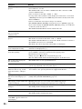
The system cannot play the following discs:
• CD-ROM/CD-R/CD-RW other than those recorded in the formats listed on page 5
• CD-ROM recorded in PHOTO CD format
• Data part of CD-Extra
• CD Graphics disc
• DVD Audio
• DATA DVD that does not contain MP3 files, JPEG image files, or DivX video files
•DVD-RAM
• Super Audio CD
Also, the system cannot play the following discs:
• A DVD VIDEO with a different region code (page 7)
• A disc that has a non-standard shape (e.g., card, heart)
• A disc with paper or stickers on it
• A disc that has the adhesive of cellophane tape or a sticker still left on it
In some cases, CD-R/CD-RW/DVD-R/DVD-RW/DVD+R/DVD+RW cannot be played on this system
due to the recording quality or physical condition of the disc, or the characteristics of the recording
device and authoring software.
The disc will not play if it has not been correctly finalized. For more information, refer to the operating
instructions for the recording device.
Note that some playback functions may not work with some DVD+RWs/DVD+Rs, even if they have
been correctly finalized. In this case, view the disc by normal playback. Also some DATA CDs/DATA
DVDs created in Packet Write format cannot be played.
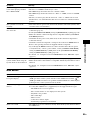
Music discs encoded with copyright protection technologies
This product is designed to play back discs that conform to the Compact Disc (CD) standard.
Recently, various music discs encoded with copyright protection technologies are marketed by some
record companies. Please be aware that among those discs, there are some that do not conform to the
CD standard and may not be playable by this product.
Example of discs that the system cannot play
Note about CD-R/CD-RW/DVD-R/DVD-RW/DVD+R/DVD+RW

7
GB
Note on DualDiscs
A DualDisc is a two sided disc product which mates DVD recorded material on one side with digital
audio material on the other side. However, since the audio material side does not conform to the
Compact Disc (CD) standard, playback on this product is not guaranteed.
• This system can play a Multi Session CD when an MP3 file is contained in the first session. Any
subsequent MP3 files recorded in later sessions can also be played back.
• This system can play a Multi Session CD when a JPEG image file is contained in the first session.
Any subsequent JPEG image files recorded in later sessions can also be played back.
• If MP3 files and JPEG image files in music CD format or video CD format are recorded in the first
session, only the first session will be played back.
Your system has a region code printed on the rear of the control unit and will only play a DVD labeled
with the same region code.
A DVD VIDEO labeled will also play on this system.
If you try to play any other DVD VIDEO, the message [Playback prohibited by area limitations.] will
appear on the TV screen. Depending on the DVD VIDEO, no region code indication may be given even
though playing the DVD VIDEO is prohibited by area restrictions.
Some playback operations on a DVD or VIDEO CD may be intentionally set by software producers.
Since this system will play a DVD or VIDEO CD according to the disc contents the software producers
designed, some playback features may not be available. Be sure to read the operating instructions
supplied with the DVD or VIDEO CD.
This product incorporates copyright protection technology that is protected by U.S. patents and other
intellectual property rights. Use of this copyright protection technology must be authorized by
Macrovision, and is intended for home and other limited viewing uses only unless otherwise authorized
by Macrovision. Reverse engineering or disassembly is prohibited.
This system incorporates with Dolby* Digital and the DTS** Digital Surround System.
* Manufactured under license from Dolby Laboratories.
Dolby, Pro Logic, and the double-D symbol are trademarks of Dolby Laboratories.
** Manufactured under license under U.S. Patent #’s: 5,451,942; 5,956,674; 5,974,380; 5,978,762; 6,487,535 &
other U.S. and worldwide patents issued & pending.
DTS and DTS 2.0 + Digital Out are registered trademarks and the DTS logos and Symbol are trademarks of DTS,
Inc. © 1996-2007 DTS, Inc. All Rights Reserved.
About Multi Session CD
Region code
Note about playback operations of a DVD or VIDEO CD
Copyrights
ALL

8
GB
This system incorporates High-Definition Multimedia Interface (HDMI
TM
) technology.
HDMI, the HDMI logo and High-Definition Multimedia Interface are trademarks or registered
trademarks of HDMI Licensing LLC.
“BRAVIA” is a trademark of Sony Corporation.

9
GB
Getting Started
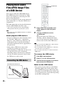
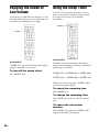
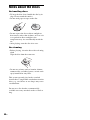
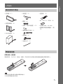
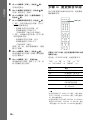
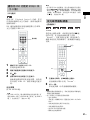
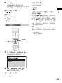
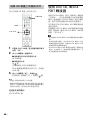
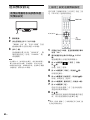
To insert batteries into the remote
Insert two R6 (size AA) batteries (supplied) by matching the 3 and # ends on the batteries to the
markings inside the compartment.
Note
• Do not leave the remote in an extremely hot or humid place.
• Do not use a new battery with an old one.
• Do not drop any foreign object into the remote casing, particularly when replacing the batteries.
Getting Started
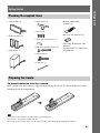
Checking the supplied items
• Control unit (1)
• Front speakers (2)
• Subwoofer (1)
• Stand cover (1)
• Screws (4)
• Seals (for stand cover) (2)
• FM wire antenna (aerial) (1)
• Video cord (1)
• Cable tie (1)
• Remote commander
(remote) (1)
• R6 (size AA) batteries (2)
• Operating Instructions (this
manual)
• Speaker and TV Connections
(supplement)
Preparing the remote

10
GB
Getting Started
• If you do not intend to use the remote for an extended period of time, remove the batteries to avoid possible damage
from battery leakage and corrosion.
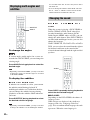
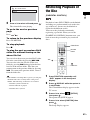
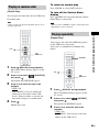
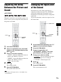
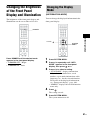
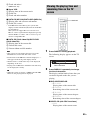
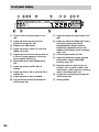
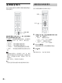
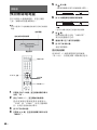
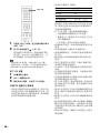
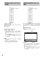
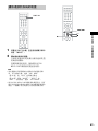
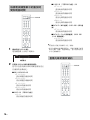
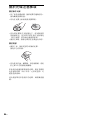
About operation of the remote
You can operate this system and TV using the supplied remote.
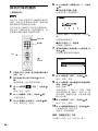
x System operation
Press TV so that TV flashes four times.
The remote enters system operation mode. When operating the system, point the remote at the center
of the panel display.
x TV operation
Press TV so that TV lights up for 1 second.
The remote enters the TV mode. To operate the system, point the remote at the TV. For details, see
“Controlling the TV with the Supplied Remote” (page 85).
Note
• Do not expose the remote sensor to direct sunlight or lighting apparatus. Doing so may cause a malfunction.
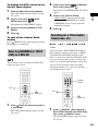
DVD HOME THEATRE SYSTEM DAV-F500
A.F.D. STD D.C.S.
FUNCTION
VOL
Remote sensor
TV

11
GB
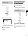
Getting Started
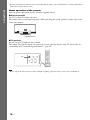
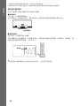
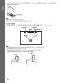
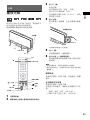
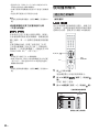
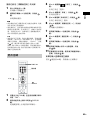
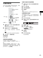
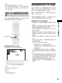
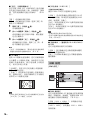
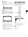
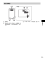
Step 1: Positioning the System
For the best possible surround sound, all the speakers other than the subwoofer should be placed at the
same distance from the listening position (A).
Place the system as illustrated below.
Note
• Leave a space for inserting/ejecting the disc (approximately 15 cm) to the right (disc slot) side of the control unit
when placing an object such as a speaker nearby.
• Do not set the speakers in an inclined position.
• Do not place the speakers in locations that are:
– Extremely hot or cold
– Dusty or dirty
– Very humid
– Subject to vibrations
– Subject to direct sunlight
• Use caution when placing the speakers and/or speaker stands attached to the speakers on a specially treated (waxed,
oiled, polished, etc.) floor, as staining or discoloration may result.
• Do not use any type of abrasive pad, scouring powder, or solvent such as alcohol or benzine.
• Do not lean or hang on the speaker, as the speaker may fall down.
• Image distortion on the TV screen may occur depending on the location of the subwoofer. In this case, place the
subwoofer away from the TV.
• Do not block the ventilation slots of the subwoofer (page 107).
A
B
A
D
C
A
A Front speaker (L (left))
B Front speaker (R (right))
C Subwoofer
D Control unit
DVD HOME THEATRE SYSTEM DAV-F500
DVD HOME THEATRE SYSTEM DAV-F500
A.F.D. STD
A.F.D. STD
D.C.S.
D.C.S.
FUNCTION
FUNCTION
VOL
VOL
Approximately 15 cm

12
GB
Getting Started
• Do not place your hand on the speaker driver when lifting the subwoofer. Doing so, the speaker driver may be
damaged. When lifting, hold the foot of the subwoofer.
Ti
p
• It is recommended to place the subwoofer on a hard floor.
• You can also place the subwoofer either side, facing the listening position.
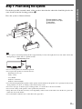
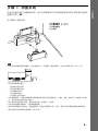
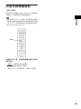
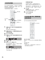
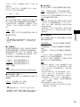
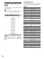
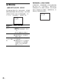
To use the speakers efficiently
Position the speakers so that the distance between each speaker and the listening position (A and B)
is the same (from 0.0 to 7.0 meters).
Note
• Place both front speakers the same distance apart as they are from the listening position (to form an isosceles
triangle).
• The front speakers should be placed at least 0.6 m apart.
• Place the front speakers forward of the TV. Make sure there are no reflecting obstacles in front of the speakers.
• Both front speakers should be pointed straight forward. Do not place the speakers at an angle.
Speaker driver
Front speaker (L)
TV
Subwoofer
Front speaker (R)
Correct
Incorrect

13
GB
Getting Started
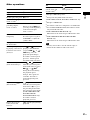
• It is recommended to place the front speakers on the edge of a table or rack, etc., to prevent sound reflection.
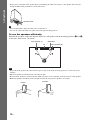
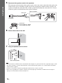
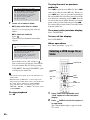
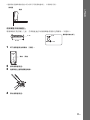
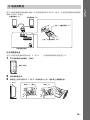
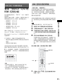
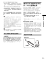
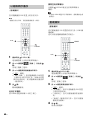
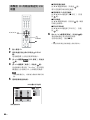
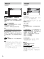
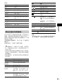
To install the speakers on a wall
Before installing the speakers on the wall, prepare screws (not supplied) that are suitable for the hole
on the rear of each speaker.
1 Remove the screw (pre-installed) at the rear of the speaker.
2 Detach the speaker stand.
3 Disconnect the speaker cords from the speaker.
4 Take the speaker stand out.
Recommended
Side view
30 mm
4 mm
Hole on the rear of
the speaker
5 mm
10 mm
Screw (pre-installed)

14
GB
Getting Started
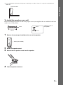
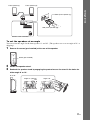
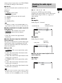
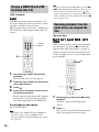
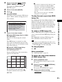
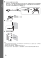
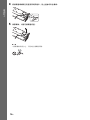
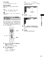
5 Reconnect the speaker cords to the speakers.
The connector and color tube of the speaker cords are the same color as the label of the jacks to be
connected. Be sure to match the speaker cords to the appropriate terminals on the speakers: the
speaker cord with the color tube to 3, and the speaker cord without the color tube to #. Do not
catch the speaker cord insulation in the speaker terminals.
6 Fasten the screws to the wall.
7 Hang the speakers on the screws.
Note
• Use screws that are suitable for the wall material and strength. As a plaster board wall is especially fragile, attach
the screws securely to a beam and fasten them to the wall. Install the speakers on a vertical and flat wall where
reinforcement is applied.
• Contact a screw shop or installer regarding the wall material or screws to be used.
• Sony is not responsible for accident or damage caused by improper installation, insufficient wall strength or
improper screw installation, natural calamity, etc.
Color tube
(–)
(+)
Connector
Rear of speaker
Color tube
Front speaker (L): White
Front speaker (R): Red
5 to 7 mm
Rear of the speaker

15
GB
Getting Started
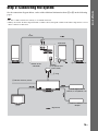
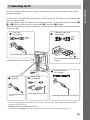
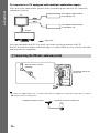
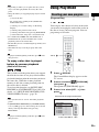
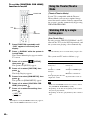
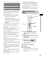
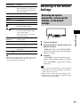
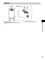
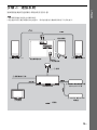
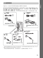
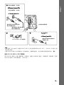
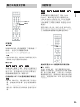
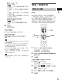
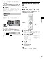
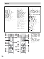
Step 2: Connecting the System
See the connection diagram below, and read the additional information from 1 to 6 on the following
pages.
Note
• Be sure to make connections securely to avoid hum and noise.
• When you connect another component with a volume control, turn up the volume of the other components to a level
where sound is not distorted.
DVD HOME THEATRE SYSTEM DAV-F500
A.F.D. STD D.C.S.
FUNCTION
VOL
SPEAKER
IMPEDANCE USE 3
FRONT R FRONT L
SYSTEM CONTROL
ONLY FOR HCD-F200
6 AC power cord
(mains lead)
2 Front speaker (R)
2 Front speaker (L)
4 VCR, digital satellite
receiver, or PlayStation, etc.
3 TV
: Signal flow
Subwoofer
Bottom of the
subwoofer
5 FM wire antenna (aerial)
1 Plug
4 DIGITAL MEDIA PORT
adapter

16
GB
Getting Started
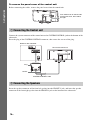
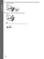
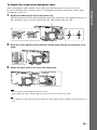
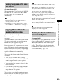
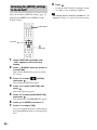
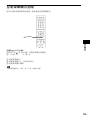
To remove the panel cover of the control unit
Before connecting the cables, remove the panel cover from the control unit.
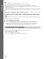
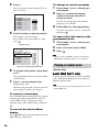
Connect the system connector of the control unit to the SYSTEM CONTROL jack on the bottom of the
subwoofer.
Insert the plug of the SYSTEM CONTROL connector, then secure the screws of the plug.
Insert the speaker connector of the front left speaker into the FRONT L jack, and insert the speaker
connector of the front right speaker into the FRONT R jack on the bottom of the subwoofer.
1 Connecting the Control unit
2 Connecting the Speakers
A
U
D
I
O
I
N
V
I
D
E
O
R
L
T
V
A
N
T
E
N
N
A
P
B
/
C
B
P
R
/
C
R
Y
C
O
M
P
O
N
E
N
T
V
I
D
E
O
O
U
T
C
O
A
X
I
A
L
D
I
G
I
T
A
L
O
U
T
D
I
G
I
T
A
L
I
N
O
P
T
I
C
A
L
D
I
G
I
T
A
L
I
N
O
P
T
I
C
A
L
D
I
G
I
T
A
L
I
N
C
O
A
X
I
A
L
T
V
S
A
T
/
C
A
B
L
E
D
M
P
O
R
T
S
A
T
/
C
A
B
L
E
V
I
D
E
O
O
U
T
D
C
5
V
0
.
7
A
M
a
x
O
U
T
F
M
7
5
C
O
A
X
I
A
L
Push the B mark on the left side
of the panel cover, then slide to
the right.
SPEAKER
IMPEDANCE USE 3
FRONT R FRONT L
SYSTEM CONTROL
ONLY FOR HCD-F200
Rear of the control unit
Bottom of the subwoofer
Screws
Plug
SYSTEM CONTROL cable

17
GB
Getting Started
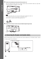
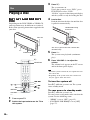
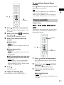
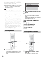
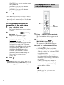
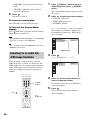
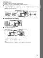
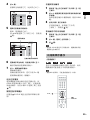
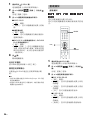
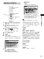
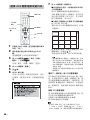
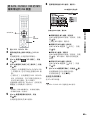
To set the speakers at an angle
You can select the angle for the front speaker: 0° and 10°. (The speakers are set to an angle of 10° at
shipping.)
1 Remove the screw (pre-installed) at the rear of the speaker.
2 Detach the speaker stand.
3 Reattach the speaker stand by engaging the protrusions on the stand in the holes for
either angle 0° or 10°.
SPEAKER
IMPEDANCE USE 3
FRONT R FRONT L
SYSTEM CONTROL
ONLY FOR HCD-F200
S
P
E
A
K
E
R
IM
P
E
D
A
N
C
E
U
S
E
3
FRONT R
FRONT L
Bottom of the subwoofer
Red (Front speaker (R))
White (Front speaker (L))
Front speaker (R)Front speaker (L)
Screw (pre-installed)
0° or 10°
Angle: 0° (vertical) Angle: 10°

18
GB
Getting Started
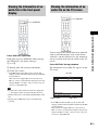
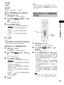
4 Thread the speaker cord though the slit of the stand base to prevent the cord being
twisted or pinched.
5 Tighten the screw to secure the speaker stand.
Note
• Be careful not to pinch the speaker cords while tightening screws.

19
GB
Getting Started
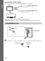
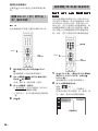
Be sure to disconnect the AC power cords of all components from their wall outlets (mains) before
making connections.
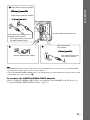
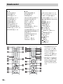
To listen to TV sound from the speakers of the system, connect the TV and the system with the audio
cord (not supplied) (A).
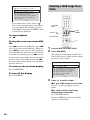
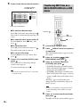
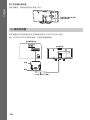
For video output to your TV, check the video input jacks of the TV, and select connection method A,
B, or C. Picture quality improves in order from A (standard) to C (HDMI).
When the TV has the digital optical output jack, you can improve sound quality by connecting with the
digital cord (B).
* If your TV accepts progressive format signals, use this connection and set the output signal of the system to
progressive format (page 27).
** HDMI (High-Definition Multimedia Interface)
If your TV has the HDMI jack, use this connection and select the type of output signal (page 27).
3 Connecting the TV
A
U
D
I
O
I
N
V
I
D
E
O
R
L
T
V
A
N
T
E
N
NA
P
B
/C
B
P
R
/C
R
Y
C
O
M
P
O
N
EN
T
V
I
D
E
O
O
U
T
C
O
A
XI
A
L
D
IG
I
T
A
L
O
U
T
D
I
G
I
T
A
L
I
N
O
P
T
I
C
A
L
D
I
G
I
T
A
L
I
N
O
P
T
I
C
A
L
D
I
G
I
T
A
L
I
N
C
O
A
X
I
A
L
T
V
S
A
T
/
C
A
B
LE
D
M
P
O
R
T
S
A
T
/
C
A
B
LE
V
I
D
E
O
O
U
T
D
C
5
V
0
.
7
A
M
a
x
O
U
T
F
M
7
5
C
O
A
X
I
A
L
O
U
T
DIGITAL IN
OPTICAL
T
V
VIDEO
VIDEO
O
UT
AUDIO IN
R
L
TV
P
B
/C
B
P
R
/C
R
Y
COMPONENT
V
I
D
E
O
O
U
T
Connector panel of the control unit
To the COMPONENT VIDEO IN jacks
of the TV
To the HDMI IN jack of the TV
To the VIDEO IN jack of
the TV
To the AUDIO OUT jacks of the TV
Component video cord
(not supplied)*
Video cord
(supplied)
HDMI** cable
(not supplied)
Audio cord
(not supplied)
Green
Blue
Red
White
Red
To the digital optical output jack of the TV
Digital optical cord
(not supplied)

20
GB
Getting Started
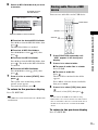
Note
• When connecting the jack, insert the plug into the jack as far as it will go.
• When connecting the digital optical cord, insert the connector until it clicks (B).
• During the “DMPORT” function, video signal is not output from the HDMI OUT and VIDEO OUT
(COMPONENT) jacks. Select connection method A to obtain pictures since the video signal is output from the
VIDEO OUT (VIDEO) jack.
• The system can accept both digital and analog signals. Digital signals have priority over analog signals. (COAXIAL
has priority over OPTICAL.) If the digital signal ceases, the analog signal will be processed after 2 seconds.
Ti
p
• You can connect another component, such as a VCR, digital satellite receiver, or PlayStation, to the TV (AUDIO
IN) jack (A) or TV (DIGITAL IN OPTICAL) jack (B) instead of the TV.
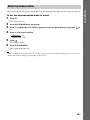
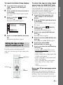
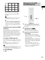
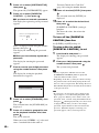
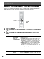
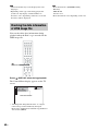
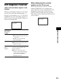
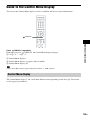
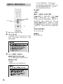
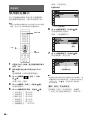
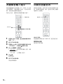
To change the color system (PAL or NTSC) (Southeast Asian models
only)
Depending on the TV to be connected, you may be required to select either PAL or NTSC for the color
system.
The initial setting of the system is NTSC.
1 Turn off the system by pressing \/1.
2 Turn on the system by pressing \/1 while pressing VOL – on the front panel.
Each time you perform this operation, the color system toggles between PAL and NTSC.
“NTSC” lights up in the front panel display when the color system is set to NTSC.
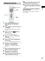
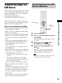
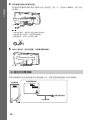
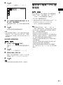
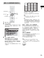
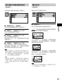
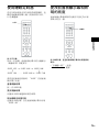
You can enjoy the connected component using the speakers of the system.
• Digital satellite receiver, etc.: A
• DIGITAL MEDIA PORT adapter: B
• AV receiver, etc.: C (only when DVD function is selected)
4 Connecting the other components
ページが読み込まれています...
ページが読み込まれています...
ページが読み込まれています...
ページが読み込まれています...
ページが読み込まれています...
ページが読み込まれています...
ページが読み込まれています...
ページが読み込まれています...
ページが読み込まれています...
ページが読み込まれています...
ページが読み込まれています...
ページが読み込まれています...
ページが読み込まれています...
ページが読み込まれています...
ページが読み込まれています...
ページが読み込まれています...
ページが読み込まれています...
ページが読み込まれています...
ページが読み込まれています...
ページが読み込まれています...
ページが読み込まれています...
ページが読み込まれています...
ページが読み込まれています...
ページが読み込まれています...
ページが読み込まれています...
ページが読み込まれています...
ページが読み込まれています...
ページが読み込まれています...
ページが読み込まれています...
ページが読み込まれています...
ページが読み込まれています...
ページが読み込まれています...
ページが読み込まれています...
ページが読み込まれています...
ページが読み込まれています...
ページが読み込まれています...
ページが読み込まれています...
ページが読み込まれています...
ページが読み込まれています...
ページが読み込まれています...
ページが読み込まれています...
ページが読み込まれています...
ページが読み込まれています...
ページが読み込まれています...
ページが読み込まれています...
ページが読み込まれています...
ページが読み込まれています...
ページが読み込まれています...
ページが読み込まれています...
ページが読み込まれています...
ページが読み込まれています...
ページが読み込まれています...
ページが読み込まれています...
ページが読み込まれています...
ページが読み込まれています...
ページが読み込まれています...
ページが読み込まれています...
ページが読み込まれています...
ページが読み込まれています...
ページが読み込まれています...
ページが読み込まれています...
ページが読み込まれています...
ページが読み込まれています...
ページが読み込まれています...
ページが読み込まれています...
ページが読み込まれています...
ページが読み込まれています...
ページが読み込まれています...
ページが読み込まれています...
ページが読み込まれています...
ページが読み込まれています...
ページが読み込まれています...
ページが読み込まれています...
ページが読み込まれています...
ページが読み込まれています...
ページが読み込まれています...
ページが読み込まれています...
ページが読み込まれています...
ページが読み込まれています...
ページが読み込まれています...
ページが読み込まれています...
ページが読み込まれています...
ページが読み込まれています...
ページが読み込まれています...
ページが読み込まれています...
ページが読み込まれています...
ページが読み込まれています...
ページが読み込まれています...
ページが読み込まれています...
ページが読み込まれています...
ページが読み込まれています...
ページが読み込まれています...
ページが読み込まれています...
ページが読み込まれています...
ページが読み込まれています...
ページが読み込まれています...
ページが読み込まれています...
ページが読み込まれています...
ページが読み込まれています...
ページが読み込まれています...
ページが読み込まれています...
ページが読み込まれています...
ページが読み込まれています...
ページが読み込まれています...
ページが読み込まれています...
ページが読み込まれています...
ページが読み込まれています...
ページが読み込まれています...
ページが読み込まれています...
ページが読み込まれています...
ページが読み込まれています...
ページが読み込まれています...
ページが読み込まれています...
ページが読み込まれています...
ページが読み込まれています...
ページが読み込まれています...
ページが読み込まれています...
ページが読み込まれています...
ページが読み込まれています...
ページが読み込まれています...
ページが読み込まれています...
ページが読み込まれています...
ページが読み込まれています...
ページが読み込まれています...
ページが読み込まれています...
ページが読み込まれています...
ページが読み込まれています...
ページが読み込まれています...
ページが読み込まれています...
ページが読み込まれています...
ページが読み込まれています...
ページが読み込まれています...
ページが読み込まれています...
ページが読み込まれています...
ページが読み込まれています...
ページが読み込まれています...
ページが読み込まれています...
ページが読み込まれています...
ページが読み込まれています...
ページが読み込まれています...
ページが読み込まれています...
ページが読み込まれています...
ページが読み込まれています...
ページが読み込まれています...
ページが読み込まれています...
ページが読み込まれています...
ページが読み込まれています...
ページが読み込まれています...
ページが読み込まれています...
ページが読み込まれています...
ページが読み込まれています...
ページが読み込まれています...
ページが読み込まれています...
ページが読み込まれています...
ページが読み込まれています...
ページが読み込まれています...
ページが読み込まれています...
ページが読み込まれています...
ページが読み込まれています...
ページが読み込まれています...
ページが読み込まれています...
ページが読み込まれています...
ページが読み込まれています...
ページが読み込まれています...
ページが読み込まれています...
ページが読み込まれています...
ページが読み込まれています...
ページが読み込まれています...
ページが読み込まれています...
ページが読み込まれています...
ページが読み込まれています...
ページが読み込まれています...
ページが読み込まれています...
ページが読み込まれています...
ページが読み込まれています...
ページが読み込まれています...
ページが読み込まれています...
ページが読み込まれています...
ページが読み込まれています...
ページが読み込まれています...
ページが読み込まれています...
ページが読み込まれています...
ページが読み込まれています...
ページが読み込まれています...
ページが読み込まれています...
ページが読み込まれています...
ページが読み込まれています...
ページが読み込まれています...
ページが読み込まれています...
ページが読み込まれています...
ページが読み込まれています...
ページが読み込まれています...
ページが読み込まれています...
ページが読み込まれています...
ページが読み込まれています...
ページが読み込まれています...
ページが読み込まれています...
ページが読み込まれています...
ページが読み込まれています...
-
 1
1
-
 2
2
-
 3
3
-
 4
4
-
 5
5
-
 6
6
-
 7
7
-
 8
8
-
 9
9
-
 10
10
-
 11
11
-
 12
12
-
 13
13
-
 14
14
-
 15
15
-
 16
16
-
 17
17
-
 18
18
-
 19
19
-
 20
20
-
 21
21
-
 22
22
-
 23
23
-
 24
24
-
 25
25
-
 26
26
-
 27
27
-
 28
28
-
 29
29
-
 30
30
-
 31
31
-
 32
32
-
 33
33
-
 34
34
-
 35
35
-
 36
36
-
 37
37
-
 38
38
-
 39
39
-
 40
40
-
 41
41
-
 42
42
-
 43
43
-
 44
44
-
 45
45
-
 46
46
-
 47
47
-
 48
48
-
 49
49
-
 50
50
-
 51
51
-
 52
52
-
 53
53
-
 54
54
-
 55
55
-
 56
56
-
 57
57
-
 58
58
-
 59
59
-
 60
60
-
 61
61
-
 62
62
-
 63
63
-
 64
64
-
 65
65
-
 66
66
-
 67
67
-
 68
68
-
 69
69
-
 70
70
-
 71
71
-
 72
72
-
 73
73
-
 74
74
-
 75
75
-
 76
76
-
 77
77
-
 78
78
-
 79
79
-
 80
80
-
 81
81
-
 82
82
-
 83
83
-
 84
84
-
 85
85
-
 86
86
-
 87
87
-
 88
88
-
 89
89
-
 90
90
-
 91
91
-
 92
92
-
 93
93
-
 94
94
-
 95
95
-
 96
96
-
 97
97
-
 98
98
-
 99
99
-
 100
100
-
 101
101
-
 102
102
-
 103
103
-
 104
104
-
 105
105
-
 106
106
-
 107
107
-
 108
108
-
 109
109
-
 110
110
-
 111
111
-
 112
112
-
 113
113
-
 114
114
-
 115
115
-
 116
116
-
 117
117
-
 118
118
-
 119
119
-
 120
120
-
 121
121
-
 122
122
-
 123
123
-
 124
124
-
 125
125
-
 126
126
-
 127
127
-
 128
128
-
 129
129
-
 130
130
-
 131
131
-
 132
132
-
 133
133
-
 134
134
-
 135
135
-
 136
136
-
 137
137
-
 138
138
-
 139
139
-
 140
140
-
 141
141
-
 142
142
-
 143
143
-
 144
144
-
 145
145
-
 146
146
-
 147
147
-
 148
148
-
 149
149
-
 150
150
-
 151
151
-
 152
152
-
 153
153
-
 154
154
-
 155
155
-
 156
156
-
 157
157
-
 158
158
-
 159
159
-
 160
160
-
 161
161
-
 162
162
-
 163
163
-
 164
164
-
 165
165
-
 166
166
-
 167
167
-
 168
168
-
 169
169
-
 170
170
-
 171
171
-
 172
172
-
 173
173
-
 174
174
-
 175
175
-
 176
176
-
 177
177
-
 178
178
-
 179
179
-
 180
180
-
 181
181
-
 182
182
-
 183
183
-
 184
184
-
 185
185
-
 186
186
-
 187
187
-
 188
188
-
 189
189
-
 190
190
-
 191
191
-
 192
192
-
 193
193
-
 194
194
-
 195
195
-
 196
196
-
 197
197
-
 198
198
-
 199
199
-
 200
200
-
 201
201
-
 202
202
-
 203
203
-
 204
204
-
 205
205
-
 206
206
-
 207
207
-
 208
208
-
 209
209
-
 210
210
-
 211
211
-
 212
212
-
 213
213
-
 214
214
-
 215
215
-
 216
216
-
 217
217
-
 218
218
-
 219
219


