
EN
DE
FR
ES
PT
ZH
M211821EN-D
Quick Guide
Vaisala VaiNet Wireless Access Point
AP10

PUBLISHED BY
Vaisala Oyj
Vanha Nurmijärventie 21, FI-01670 Vantaa, Finland
P.O. Box 26, FI-00421 Helsinki, Finland
+358 9 8949 1
Visit our Internet pages at www.vaisala.com.
No part of this document may be
reproduced, published or publicly
displayed in any form or by any
means, electronic or mechanical
(including photocopying), nor
may its contents be modified,
translated, adapted, sold or
disclosed to a third party without
prior written permission of the
copyright holder. Translated
documents and translated
portions of multilingual
documents are based on the
original English versions. In
ambiguous cases, the English
versions are applicable, not the
translations.
The contents of this document are
subject to change without prior
notice.
Local rules and regulations may
vary and they shall take
precedence over the information
contained in this document.
Vaisala makes no representations
on this document’s compliance
with the local rules and
regulations applicable at any
given time, and hereby disclaims
any and all responsibilities related
thereto.
This document does not create
any legally binding obligations for
Vaisala towards customers or end
users. All legally binding
obligations and agreements are
included exclusively in the
applicable supply contract or the
General Conditions of Sale and
General Conditions of Service of
Vaisala.
This product contains software
developed by Vaisala or third
parties. Use of the software is
governed by license terms and
conditions included in the
applicable supply contract or, in
the absence of separate license
terms and conditions, by the
General License Conditions of
Vaisala Group.
This product may contain open
source software (OSS)
components. In the event this
product contains OSS
components, then such OSS is
governed by the terms and
conditions of the applicable OSS
licenses, and you are bound by
the terms and conditions of such
licenses in connection with your
use and distribution of the OSS in
this product. Applicable OSS
licenses are included in the
product itself or provided to you
on any other applicable media,
depending on each individual
product and the product items
delivered to you.

Table of Contents
English.............................................................................................................................................5
Deutsch......................................................................................................................................... 13
Français.........................................................................................................................................21
Español.........................................................................................................................................29
Português.................................................................................................................................... 37
中文...............................................................................................................................................45
3

4 M211821EN-D

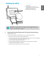
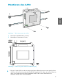
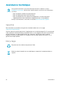
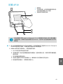
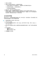
Setting Up AP10
2
3
1
1 Touchscreen.
2 Ethernet cable. You must use a
shielded cable to meet the rated EMC
performance of the device.
3 Cable from DC power supply.
AP10 requires a network connection to your viewLinc Enterprise Server and a
Network Time Protocol (NTP) server. AP10 can also use its default NTP servers if
internet is accessible from the network.
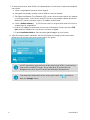
1. Connect the Ethernet cable to Ethernet port of AP10. If possible, connect to the same
network where the viewLinc Enterprise Server is, so that you can verify the connection
when doing the setup.
2. If the Ethernet cable does not provide power, connect the DC power supply:
a. Remove the DC power supply from the AP10 package.
b. The power supply comes with multiple adapters for wall sockets. Connect the adapter
you need to the power supply before attempting to use it.
c. Plug in the power supply to the wall socket.
d. Connect the plug to the power supply connector of AP10. Make sure the plug is
oriented correctly and goes in all the way.
e. Rotate the power plug slightly to lock it to the connector.
5
ENGLISH

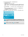
3. A setup wizard starts when AP10 is first powered up. Use the touch interface to complete
the wizard:
a. Select a language for the touchscreen display.
b. Configure the network settings so that AP10 can join the network.
c. Configure the Network Time Protocol (NTP) servers that the access point will attempt
to synchronize with. If you have a local NTP server in the network, replace one of the
default NTP server hostnames with its IP address or hostname.
d. Select a VaiNet channel (1 ... 8). Each access point in range of each other must have a
unique channel assigned to it.
e. Enter the IP address or hostname of the viewLinc Enterprise Server. Leave the TCP
port at default 12600 unless you know it has been changed.
f. Enable Installation Mode to start connecting data loggers to your system.
4. After the setup wizard is complete, wait for the display to change to the home screen
where you can see the status of the access point at a glance.
An NTP connection error continues to be shown while AP10 is synchronizing
time with the listed NTP servers. It may take up to 15 minutes for it to
disappear even when the NTP servers are reachable. Wait patiently.
To change the configuration of the access point, touch the symbol to
open the Settings screen.
6 M211821EN-D

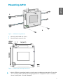
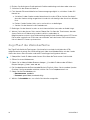
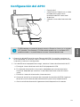
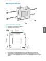
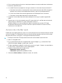
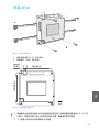
Mounting AP10
B
A
Figure 1 AP10 Mounting Methods
A Mounting with cable ties (2 pcs).
B Mounting with screws (4 pcs).
116 [4.57]
124 [4.88]
Ø3.50
[0.11]
mm
[in]
Figure 2 AP10 Screw Mounting Dimensions
1. Attach AP10 to its mounting location using the most suitable mounting option. Ensure the
unit is securely fixed if you are mounting it higher than 2 m (approx. 6 ft) or in a location
where it would pose a hazard if dropped.
7
ENGLISH

2. Point the antenna up or down for best wireless performance.
3. Connect the Ethernet cable.
4. If the Ethernet cable does not provide power, connect the DC power supply:
a. Connect the plug to the power supply connector of AP10. Make sure the plug is
oriented correctly and goes in all the way.
b. Rotate the power plug slightly to lock it to the connector.
c. Connect the power supply to the wall socket.
5. Secure the power supply so it does not fall or hang on its cable.
6. Wait for the access point to start up. Verify from the touchscreen that the access point has
an IP address, and it is connected to viewLinc.
You may also see an error message about the NTP server connection. It should disappear
within 15 minutes as the access point synchronizes its internal clock with the NTP server.
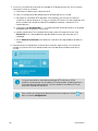
Accessing the Web Interface
The local touchscreen interface may be hard to access after AP10 has been installed. AP10 also
has a web interface that you can use to remotely view access point status and configure its
settings.
1. Verify the IP address of the access point from the touchscreen interface.
2. Open a web browser.
3. In the address field of the web browser, enter https:// and the IP address of the AP10.
For example: https://192.168.10.47
4. The default user interface language is English. If you want to use another language for this
session, select it from the drop-down menu.
5. Enter the login information:
• User name: apadmin
• Password: ap123456 (default)
6. Select Log in to access the interface.
8 M211821EN-D

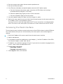
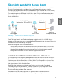
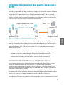
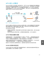
Overview of AP10 Access Point
Vaisala VaiNet Access Point AP10 is a wireless access point that collects data from VaiNet
wireless data loggers and transfers it to viewLinc Enterprise Server using a wired Ethernet
connection. AP10 implements Vaisala's proprietary VaiNet protocol. It can connect up to 32
RFL100 Data Loggers to Vaisala viewLinc Monitoring System. The wireless connection
operates on 868 MHz or 915 MHz frequency band depending on the model. For more
information on viewLinc system installation, see viewLinc Setup Guide (M211820EN).
viewLinc
Enterprise Server
AP10
Access Point
RFL100
Data Loggers
VaiNet wireless
>100 m (328 ft) range
NTP Server
Wired
network
Figure 3 AP10 in the viewLinc Monitoring System
AP10 can be powered from the Ethernet connector using Power over Ethernet (PoE) or from
the power supply connector using the included AC/DC adapter. If both power sources are
connected, the AC/DC adapter is utilized to power the device. AP10 is IP22 rated, and is
suitable for indoor industrial applications.
AP10 has two user interfaces:
• Touch interface on the front panel. Use this interface to set up the device during
installation and to locally check the connection status.
• Web interface via the Ethernet connection. This interface provides advanced
configuration features and can be accessed remotely.
AP10 Installation Location and Range
In a typical indoor space, the wireless range of AP10 is at least 100 m (328 ft). In an open space
with line-of-sight and no interfering structures, the range can be over 500 m (1640 ft). Up to 8
access points can be placed within range of each other, even side-by-side, as long as they each
have their own VaiNet channel.
Walls and ceilings are good locations for AP10. Line of sight is not required. If possible, place
AP10 in the same floor as the data loggers. Point the antenna up or down for best wireless
performance.
Avoid placing AP10 close to large metal surfaces, as they may reduce the range of the radio
signal.
9
ENGLISH

Delays in a VaiNet Network
VaiNet protocol and VaiNet devices are designed for power-ecient operation. Some of the
design choices that enable long battery life also create significant delays that the users should
be aware of.
Intermittent Radio Connections
Radio connections between VaiNet access points and data loggers are not continuous. Access
points take turns communicating in a two-minute cycle, and connected data loggers send their
measurement data to their connected access point every four minutes. This introduces various
delays:
• Data loggers that are not currently connected (new devices or ones that have fallen out of
radio contact) have to scan for available access points for a complete cycle before they
can decide what is the optimal access point for them. This means that connection
attempts typically take at least a couple of minutes. Additionally, some joining scenarios
may take multiple attempts. For example, when filling a single access point up to its full
capacity of 32 data loggers, it may take an hour for the last data logger to successfully
connect to the access point.
• Access points request missing data and issue management commands to data loggers
within their communication window. Transferring a full month's worth of measurement
data from 32 data loggers using one access point takes several hours.
Data Logger Scanning Interval
Scanning for available access points consumes power. To prevent repeated scanning from
draining their batteries, RFL100 Data Loggers shut down their radio temporarily if they can
find no access points to join. They will resume scanning after a waiting interval that gets
progressively longer if they keep failing to find an access point. The maximum interval is 8
hours and 30 minutes.
This means that when access points become available after an outage, it may take several
hours for data loggers to discover them. This is why you should always keep your access points
powered up, and why you should start your network installation by installing the viewLinc
Enterprise Server and access points first.
You can manually wake up the radio of an RFL100 Data Logger by pressing its
Refresh button. The button is located next to the service port under the silicone
plug.
More Information
For more information on AP10 Access Point, see AP10 User Guide (M211860EN) available at
www.vaisala.com/ap10.
10 M211821EN-D

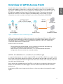
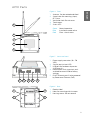
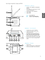
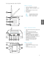
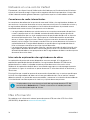
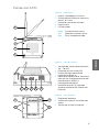
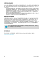
AP10 Parts
1
2
3
4
5
Figure 4 Front
1 Antenna. Can be rotated and tilted.
2 Screw holes for mounting (4 pcs),
Ø 3.2 mm.
3 Ventilation hole. Do not cover.
4 Touchscreen.
5 Status LED:
Green Normal operation
Blue Installation mode active
Red Error - check status
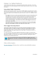
1 2 3 4 5
Figure 5 Connector Panel
1 Power supply connector (10 ... 30
VDC).
2 Service port (micro-USB).
3 USB port for hardware expansion
(USB type A).
4 Reset button. Push to restart, push
and hold to revert AP10 to factory
settings.
5 RJ-45 Ethernet port. Can be powered
by Power over Ethernet (PoE).
1
2
2
3
Figure 6 Rear
1 Product label.
2 Holes for mounting with tie wraps.
3 Housing screws. Do not remove.
11
ENGLISH

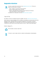
Technical Support
Contact Vaisala technical support at helpdesk@vaisala.com. Provide at least the
following supporting information:
• Product name, model, and serial number
• Name and location of the installation site
• Name and contact information of a technical person who can provide further
information on the problem
For more information, see www.vaisala.com/support.
Warranty
For standard warranty terms and conditions, see www.vaisala.com/warranty.
Please observe that any such warranty may not be valid in case of damage due to normal wear
and tear, exceptional operating conditions, negligent handling or installation, or unauthorized
modifications. Please see the applicable supply contract or Conditions of Sale for details of the
warranty for each product.
Recycling
Recycle all applicable material.
Follow the statutory regulations for disposing of the product and packaging.
12 M211821EN-D

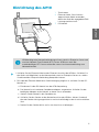
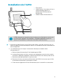
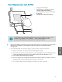
Einrichtung des AP10
2
3
1
1 Touchscreen.
2 Ethernet-Kabel. Sie müssen ein
abgeschirmtes Kabel verwenden,
damit das Gerät die angegebene EMV-
Leistung erreichen kann.
3 DC-Netzteil.
AP10 benötigt eine Netzwerkverbindung zu Ihrem viewLinc Enterprise Server und
zu einem Network Time Protocol (NTP) Server. AP10 kann auch den
standardmäßigen NTP-Server verwenden, wenn eine Internetverbindung zum
Netzwerk besteht.
1. Schließen Sie das Ethernet-Kabel an den Ethernet-Anschluss des AP10 an. Schließen Sie
das Gerät nach Möglichkeit an das Netzwerk des viewLinc Enterprise Servers an, sodass
Sie während des Setups die Verbindung überprüfen können.
2. Falls über das Ethernet-Kabel keine Stromversorgung möglich ist, schließen Sie das DC-
Netzteil an:
a. Entnehmen Sie das DC-Netzteil aus der AP10-Verpackung.
b. Das Netzteil ist mit mehreren Steckdosenadaptern ausgestattet. Schließen Sie den
benötigten Adapter an das Netzteil an, bevor Sie es verwenden.
c. Stecken Sie das Netzteil in die Steckdose ein.
d. Schließen Sie den Stecker an den Netzteilanschluss des AP10 an. Achten Sie darauf,
dass der Stecker richtig ausgerichtet ist und sich vollständig in den Anschluss drücken
lässt.
e. Drehen Sie den Stecker leicht, um ihn am Anschluss zu befestigen.
13
DEUTSCH

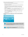
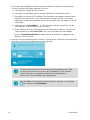
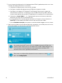
3. Setup-Assistent wird aktiviert, wenn der AP10 erstmals eingeschaltet wird. Schließen Sie
den Assistenten über den Touchscreen ab:
a. Wählen Sie eine Sprache für die Touchscreenanzeige aus.
b. Konfigurieren Sie die Netzwerkeinstellungen, damit der AP10 eine Verbindung mit
dem Netzwerk herstellen kann.
c. Konfigurieren Sie die NTP-Server, mit denen der Access Point synchronisieren soll.
Wenn ein lokaler NTP-Server im Netzwerk vorhanden ist, ersetzen Sie einen
Hostnamen der standardmäßigen NTP-Server durch dessen IP-Adresse oder
Hostnamen.
d. Wählen Sie VaiNet-Kanal (1 ... 8). Wenn sich mehrere Access Points im selben Bereich
befinden, muss jedem einzelnen ein einzigartiger Kanal zugewiesen sein.
e. Geben Sie die IP-Adresse oder den Hostnamen des viewLinc Enterprise Servers ein.
Lassen Sie den Standardwert 12600 für TCP-Port unverändert, sofern er Ihres
Wissens nicht geändert wurde.
f. Aktivieren Sie Installationsmodus, damit Datenlogger sich mit Ihrem System
verbinden können.
4. Nachdem der Setup-Assistent abgeschlossen ist, warten Sie, bis die Anzeige zum
Startbildschirm wechselt. Dort wird Ihnen der Status des Access Point auf einen Blick
angezeigt.
Ein NTP-Verbindungsfehler wird weiterhin angezeigt, während der AP10 die
Uhrzeit mit den aufgelisteten NTP-Servern synchronisiert. Es kann bis zu 15
Minuten dauern, bis die Fehleranzeige verschwunden ist, auch wenn die NTP-
Server erreichbar sind. Warten Sie.
Sie können die Konfiguration des Access Point ändern, indem Sie über das
Symbol den Bildschirm Einstellungen önen.
14 M211821EN-D

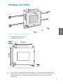
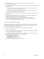
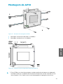
Montieren des AP10
B
A
Abbildung 7 Befestigungsarten des AP10
A Montage mit Kabelbindern (2 Stück).
B Montage mit Schrauben (4 Stück).
116 [4.57]
124 [4.88]
Ø3.50
[0.11]
mm
[in]
Abbildung 8 Abmessungen der AP10-Schraubbefestigung
1. Bringen Sie den AP10 mit der am besten geeigneten Befestigungsart an der gewünschten
Stelle an. Stellen Sie sicher, dass die Einheit fest angebracht ist, wenn sie in einer Höhe von
mehr als 2 m oder an einer Stelle angebracht wird, an der sie ein Sicherheitsrisiko
darstellen würde, wenn sie herunterfiele.
15
DEUTSCH

2. Richten Sie die Antenne für die optimale Drahtlosverbindung nach oben oder unten aus.
3. Schließen Sie das Ethernet-Kabel an.
4. Falls über das Ethernet-Kabel keine Stromversorgung möglich ist, schließen Sie das DC-
Netzteil an:
a. Schließen Sie den Stecker an den Netzteilanschluss des AP10 an. Achten Sie darauf,
dass der Stecker richtig ausgerichtet ist und sich vollständig in den Anschluss drücken
lässt.
b. Drehen Sie den Stecker leicht, um in am Anschluss zu befestigen.
c. Stecken Sie das Netzteil in die Steckdose ein.
5. Befestigen Sie das Netzteil so, dass es nicht herunterfallen kann oder am Kabel hängt.
6. Warten Sie, bis der Access Point startet. Überprüfen Sie über den Touchscreen, dass der
Access Point eine IP-Adresse hat und mit viewLinc verbunden ist.
Möglicherweise erscheint eine Fehlermeldung bezüglich der Verbindung zum NTP-Server.
Diese sollte innerhalb von 15 Minuten verschwinden, weil der Access Point seine interne
Uhr mit dem NTP-Server synchronisiert.
Zugri auf die Weboberfläche
Der Zugri auf die lokale Touchscreen-Schnittstelle ist nach der Installation des AP10
möglicherweise schwierig. Der AP10 verfügt auch über eine Weboberfläche mit der Sie den
Status des Access Point einsehen und seine Einstellungen konfigurieren können.
1. Überprüfen Sie die IP-Adresse des Access Point über die Touchscreen-Schnittstelle.
2. Önen Sie einen Webbrowser.
3. Geben Sie im Adressfeld des Browsers https:// und die IP-Adresse des AP10 ein.
Beispiel: https://192.168.10.47
4. Die Standardsprache der Benutzeroberfläche ist Englisch. Wenn Sie eine andere Sprache
für diese Sitzung verwenden möchten, wählen Sie sie im Dropdownmenü aus.
5. Geben Sie die Anmeldedaten ein:
• Benutzername: apadmin
• Passwort: ap123456 (standardmäßig)
6. Wählen Sie Anmelden aus, um auf die Schnittstelle zuzugreifen.
16 M211821EN-D

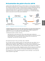
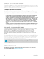
Übersicht zum AP10 Access Point
Der Vaisala VaiNet AP10 Access Point ist ein drahtloser Access Point, der Daten von VaiNet
Drahtlos-Datenloggern erfasst und diese über eine Ethernet-Verbindung an viewLinc
Enterprise Server übermittelt. Der AP10 verwendet das VaiNet-Protokoll von Vaisala. Er kann
bis zu 32 RFL100-Datenlogger mit dem Vaisala viewLinc-Überwachungssystem verbinden. Die
Funkverbindung wird je nach Modell im 868 MHz- oder 915 MHz-Frequenzband betrieben.
Weitere Informationen zur Installation des viewLinc-Systems finden Sie im viewLinc Setup
Guide (M211820EN).
viewLinc
Enterprise Server
AP10
Access Point
RFL100
Datenlogger
VaiNet WLAN
Reichweite > 100 m (328 ft)
NTP-Server
Verkabeltes
Netzwerk
Abbildung 9 AP10 im viewLinc-Überwachungssystem
Der AP10 kann über Ethernet (PoE) oder über das Netzteil einschließlich AC/DC-Adapter mit
Strom versorgt werden. Wenn beide Stromquellen angeschlossen sind, wird der AC/DC-
Adapter zur Versorgung des Geräts verwendet. Der AP10 entspricht der Schutzart IP22 und ist
für industrielle Innenanwendungen ausgelegt.
Der AP10 verfügt über zwei Benutzeroberflächen:
• Touchscreen-Schnittstelle auf der Vorderseite. Diese Schnittstelle dient zur Einrichtung
des Geräts während der Installation und zur lokalen Überprüfung des Verbindungsstatus.
• Weboberfläche über die Ethernet-Verbindung. Diese Schnittstelle bietet erweiterte
Konfigurationsfunktionen und einen Remote-Zugri auf das Gerät an.
Installationsstandort und -bereich des AP10
In einer typischen Innenumgebung beträgt die Reichweite des AP10 mindestens 100 m (328
Fuß). In einer oenen Umgebung mit direkter Sichtverbindung und ohne abschirmende
Strukturen kann die Reichweite mehr als 500 m (1640 Fuß) betragen. Bis zu 8 Access Points
können in Reichweite voneinander platziert werden, auch nebeneinander, sofern sie jeweils
über einen eigenen VaiNet-Kanal verfügen.
Der AP10 sollte idealerweise an Wänden oder Decken montiert werden. Eine direkte
Sichtverbindung ist nicht erforderlich. Platzieren Sie den AP10 nach Möglichkeit auf der
gleichen Etage wie die Datenlogger. Richten Sie die Antenne für die optimale
Drahtlosverbindung nach oben oder unten aus.
Vermeiden Sie es, den AP10 in der Nähe von großen metallischen Oberflächen zu
positionieren, da hierdurch die Reichweite des Funksignals verringert wird.
17
DEUTSCH

Verzögerungen in einem VaiNet-Netzwerk
VaiNet-Protokoll und VaiNet-Geräte sind für einen energieezienten Betrieb ausgelegt. Einige
Designentscheidungen, die eine lange Akkulaufzeit ermöglichen, verursachen auch erhebliche
Verzögerungen, die den Benutzern bekannt sein sollten.
Unterbrochene Funkverbindungen
Funkverbindungen zwischen VaiNet-Access Points und Datenloggern sind nicht kontinuierlich.
Access Points wechseln sich im Zwei-Minuten-Takt ab, und verbundene Datenlogger senden
ihre Messdaten alle vier Minuten an ihren verbundenen Access Point. Dies führt zu
verschiedenen Verzögerungen:
• Datenlogger, die derzeit nicht verbunden sind (neue Geräte oder Geräte, die nicht mehr
im Funkkontakt stehen), müssen einen vollständigen Zyklus nach verfügbaren Access
Points suchen, bevor sie entscheiden können, welcher Access Point für sie optimal ist.
Dies bedeutet, dass Verbindungsversuche in der Regel mindestens einige Minuten dauern.
Darüber hinaus können einige Verbindungsszenarien mehrere Versuche erfordern. Wenn
Sie beispielsweise einen einzelnen Access Point bis zu seiner vollen Kapazität von 32
Datenloggern füllen, kann es eine Stunde dauern, bis der letzte Datenlogger eine
erfolgreiche Verbindung zum Access Point hergestellt hat.
• Access Points fordern fehlende Daten an und geben innerhalb ihres
Kommunikationsfensters Verwaltungsbefehle an die Datenlogger aus. Die Übertragung
von Messdaten eines ganzen Monats von 32 Datenloggern über einen einzigen Access
Point dauert mehrere Stunden.
Scanintervall für Datenlogger
Das Scannen nach verfügbaren Access Points verbraucht Leistung. Um zu verhindern, dass
durch wiederholtes Scannen die Batterien entladen werden, wird der Funk von RFL100-
Datenloggern vorübergehend heruntergefahren, wenn keine Access Points zum Verbinden
gefunden werden. Die Logger setzen den Scanvorgang nach einem Warteintervall fort, das
immer länger wird, wenn sie keinen Access Point finden. Das maximale Intervall beträgt 8
Stunden und 30 Minuten.
Das bedeutet: Wenn Access Points nach einem Ausfall verfügbar werden, kann es einige
Stunden dauern, bis sie von den Datenloggern erkannt werden. Aus diesem Grund sollten Sie
Ihre Access Points immer eingeschaltet lassen und Ihre Netzwerkinstallation so beginnen, dass
Sie zuerst den viewLinc Enterprise Server und die Access Points installieren.
Sie können den Funk eines RFL100-Datenloggers manuell aktivieren, indem Sie
dessen Schaltfläche Refresh drücken. Die Schaltfläche befindet sich neben der
Serviceschnittstelle unter dem Silikonstecker.
Weitere Informationen
Weitere Informationen zum AP10 Access Point finden Sie im AP10 User Guide (M211860EN)
unter www.vaisala.com/ap10.
18 M211821EN-D

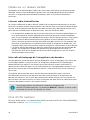
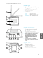
Komponenten des AP10
1
2
3
4
5
Abbildung 10 Vorderseite
1 Antenne. Kann gedreht und gekippt
werden.
2 Schraublöcher zur Montage (4 Stück),
3,2 mm Durchmesser.
3 Lüftungsloch. Nicht abdecken.
4 Touchscreen.
5 Status-LED:
Grün Normalbetrieb
Blau Installationsmodus aktiv
Rot Fehler – Status überprüfen
1 2 3 4 5
Abbildung 11 Anschlussblende
1 Stromanschluss (10 ... 30 VDC).
2 Serviceschnittstelle (Micro-USB).
3 USB-Anschluss für
Hardwareerweiterung (USB-Typ A).
4 Reset-Taste. Zum Neustart drücken,
zum Zurücksetzen des AP10 auf die
Werkseinstellungen gedrückt halten.
5 RJ-45-Ethernet-Anschluss. Kann über
Ethernet mit Strom versorgt werden
(PoE).
1
2
2
3
Abbildung 12 Rückseite
1 Typenschild.
2 Löcher zur Montage mit Kabelbindern.
3 Gehäuseschrauben. Nicht entfernen.
19
DEUTSCH

Technischer Support
Wenden Sie sich an den technischen Support von Vaisala unter
helpdesk@vaisala.com. Geben Sie mindestens folgende Informationen an:
• Produktname, Modell und Seriennummer
• Name und Standort der Installation
• Name und Kontaktinformationen eines Technikers für weitere Auskünfte
Weitere Informationen finden Sie unter www.vaisala.com/support.
Gewährleistung
Unsere Standardgarantiebedingungen finden Sie unter www.vaisala.com/warranty.
Diese Garantie deckt keine Verschleißschäden, Schäden infolge außergewöhnlicher
Betriebsbedingungen, Schäden infolge unzulässiger Verwendung oder Montage oder Schäden
infolge nicht genehmigter Modifikationen ab. Einzelheiten zum Gewährleistungsumfang für
bestimmte Produkte enthalten der zugehörige Liefervertrag und die Verkaufsbedingungen.
Recycling
Recyceln Sie alle wiederverwertbaren Materialien.
Beachten Sie bei der Entsorgung von Produkten und Verpackung die gesetzlichen
Regelungen.
20 M211821EN-D
ページが読み込まれています...
ページが読み込まれています...
ページが読み込まれています...
ページが読み込まれています...
ページが読み込まれています...
ページが読み込まれています...
ページが読み込まれています...
ページが読み込まれています...
ページが読み込まれています...
ページが読み込まれています...
ページが読み込まれています...
ページが読み込まれています...
ページが読み込まれています...
ページが読み込まれています...
ページが読み込まれています...
ページが読み込まれています...
ページが読み込まれています...
ページが読み込まれています...
ページが読み込まれています...
ページが読み込まれています...
ページが読み込まれています...
ページが読み込まれています...
ページが読み込まれています...
ページが読み込まれています...
ページが読み込まれています...
ページが読み込まれています...
ページが読み込まれています...
ページが読み込まれています...
ページが読み込まれています...
ページが読み込まれています...
ページが読み込まれています...
ページが読み込まれています...
ページが読み込まれています...
ページが読み込まれています...
-
 1
1
-
 2
2
-
 3
3
-
 4
4
-
 5
5
-
 6
6
-
 7
7
-
 8
8
-
 9
9
-
 10
10
-
 11
11
-
 12
12
-
 13
13
-
 14
14
-
 15
15
-
 16
16
-
 17
17
-
 18
18
-
 19
19
-
 20
20
-
 21
21
-
 22
22
-
 23
23
-
 24
24
-
 25
25
-
 26
26
-
 27
27
-
 28
28
-
 29
29
-
 30
30
-
 31
31
-
 32
32
-
 33
33
-
 34
34
-
 35
35
-
 36
36
-
 37
37
-
 38
38
-
 39
39
-
 40
40
-
 41
41
-
 42
42
-
 43
43
-
 44
44
-
 45
45
-
 46
46
-
 47
47
-
 48
48
-
 49
49
-
 50
50
-
 51
51
-
 52
52
-
 53
53
-
 54
54


他の言語で
- español: Vaisala VaiNet AP10 Manual de usuario
- Deutsch: Vaisala VaiNet AP10 Benutzerhandbuch
- français: Vaisala VaiNet AP10 Manuel utilisateur
- português: Vaisala VaiNet AP10 Manual do usuário