Hitachi WM 10DBL Handling Instructions Manual
- カテゴリー
- パワーツール
- タイプ
- Handling Instructions Manual

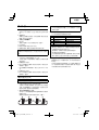
Electronic Pulse Driver
전자펄스 임팩트 드라이버
Máy vặn vít điều chỉnh điện tử dùng pin
WM 10DBL
Handling instructions
취급 설명서
Hướng dẫn sử dụng
Read through carefully and understand these instructions before use.
본 설명서를 자세히 읽고 내용을 숙지한 뒤 제품을 사용하십시오.
Đọc kỹ và hiểu rõ các hướng dẫn này trước khi sử dụng.

2
1
3
7
2
6
4
8
2
1
%
#
@
$
&
*
1
3
2
4
5
<BCL1015> <BCL1030M>
9
1
!
0
^
(
)
q
ew
t
u
y
r
t
12
34
56
78

3
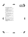
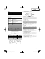
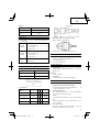
English
한국어
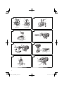
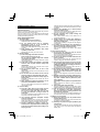
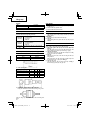
1
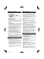
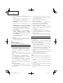
Rechargeable battery
충전식 배터리
2
Latch
래치
3
Battery cover
배터리 커버
4
Terminals
단자
5
Indication lamp
표시 램프
6
Handle
핸들
7
Insert
빼냄
8
Pull out
잡아당김
9
Push
밀기
0
Insert
빼냄
!
Pilot lamp
파일럿 램프
@
Hole for connecting the
rechargeable battery
충전 배터리 연결용 구멍
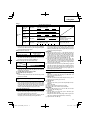
#
Movement
이동
$
Guide sleeve
가이드 슬리브
%
Hexagonal hole in the anvil
소켓의 육각구멍
^
Driver bit
드라이버 비트
&
Drill
bit
드릴 비트
*
Drill chuck adapter
드릴 척 어댑터
(
Tighten
조임
)
Loosen
풀기
q
Mode switch panel
모드 스위치 패널
w
Mode selection switch
모드 선택 스위치
e
Mode indication lamp
모드 표시 램프
r
Push button
회전 방향 전환 스위치
t
Push
밀기
y
Trigger switch
트리거 스위치
u
Light
조명
91011
12 13

4
Tiếng Việt
1
Pin sạc
2
Chốt
3
Nắp pin
4
Đầu cuối
5
Đèn báo
6
Tay cầm
7
Gắn vào
8
Kéo ra
9
Đẩy
0
Gắn vào
!
Đèn báo hiệu
@
Lỗ để lắp pin sạc
#
Chuyển động
$
Ống dẫn
%
Lỗ lục giác trong cữ chặn
^
Mũi vặn
&
Mũi khoan
*
Bộ nối đầu cặp mũi khoan
(
Siết chặt
)
Nới lỏng
q
Bảng chuyển chế độ
w
Công tắc chọn chế độ
e
Đèn báo chế độ
r
Nút nhấn
t
Đẩy
y
Công tắc khởi động
u
Đèn

5
GENERAL SAFETY RULES
WARNING!
Read all instructions
Failure to follow all instructions listed below may result in
electric shock, fi re and/or serious injury.
The term “power tool” in all of the warnings listed below
refers to your mains operated (corded) power tool or battery
operated (cordless) power tool.
SAVE THESE INSTRUCTIONS
1) Work area safety
a) Keep work area clean and well lit.
Cluttered or dark areas invite accidents.
b) Do not operate power tools in explosive
atmospheres, such as in the presence of
fl ammable liquids, gases or dust.
Power tools create sparks which may ignite the dust
or fumes.
c) Keep children and bystanders away while
operating a power tool.
Distractions can cause you to lose control.
2) Electrical safety
a) Power tool plugs must match the outlet.
Never modify the plug in any way.
Do not use any adapter plugs with earthed
(grounded) power tools.
Unmodifi ed plugs and matching outlets will reduce
risk of electric shock.
b) Avoid body contact with earthed or grounded
surfaces, such as pipes, radiators, ranges and
refrigerators.
There is an increased risk of electric shock if your
body is earthed or grounded.
c) Do not expose
power tools to rain or wet
conditions.
Water entering a power tool will increase the risk of
electric shock.
d) Do not abuse the cord. Never use the cord for
carrying, pulling or unplugging the power tool.
Keep cord away from heat, oil, sharp edges or
moving parts.
Damaged or entangled cords increase the risk of
electric shock.
e) When operating a power tool outdoors, use an
extension cord suitable for
outdoor use.
Use of a cord suitable for outdoor use reduces the
risk of electric shock.
3) Personal safety
a) Stay alert, watch what you are doing and use
common sense when operating a power tool.
Do not use a power tool while you are tired
or under the infl uence of drugs, alcohol or
medication.
A moment of inattention while operating power tools
may result in serious personal injury.
b) Use personal protective equipment. Always
wear
eye protection.
Protective equipment such as dust mask, non-skid
safety shoes, hard hat, or hearing protection used for
appropriate conditions will reduce personal injuries.
c) Prevent unintentional starting. Ensure the
switch is in the off -position before connecting to
power source and/or battery pack, picking up or
carrying the tool.
Carrying power tools with your fi nger on the switch or
energising power tools that have the switch on invites
accidents.
d) Remove any adjusting key or wrench before
turning the power tool on.
A wrench or a key left attached to a rotating part of the
power tool may result in personal injury.
e) Do not overreach. Keep proper
footing and
balance at all times.
This enables better control of the power tool in
unexpected situations.
f) Dress properly. Do not wear loose clothing or
jewellery. Keep your hair, clothing and gloves
away from moving parts.
Loose clothes, jewellery or long hair can be caught in
moving parts.
g) If devices are provided for the connection of
dust extraction and collection facilities, ensure
these are connected and properly used.
Use of dust collection can reduce dust related
hazards.
4) Power
tool use and care
a) Do not force the power tool. Use the correct
power tool for your application.
The correct power tool will do the job better and safer
at the rate for which it was designed.
b) Do not use the power tool if the switch does not
turn it on and off .
Any power tool that cannot be controlled with the
switch is dangerous and must be repaired.
c) Disconnect the plug from the power source and/
or the battery
pack from the power tool before
making any adjustments, changing accessories,
or storing power tools.
Such preventive safety measures reduce the risk of
starting the power tool accidentally.
d) Store idle power tools out of the reach of children
and do not allow persons unfamiliar with the
power tool or these instructions to operate the
power tool.
Power tools are dangerous in the hands of untrained
users.
e) Maintain power tools. Check
for misalignment or
binding of moving parts, breakage of parts and
any other condition that may aff ect the power
tools’ operation.
If damaged, have the power tool repaired before
use.
Many accidents are caused by poorly maintained
power tools.
f) Keep cutting tools sharp and clean.
Properly maintained cutting tools with sharp cutting
edges are less likely to bind and are easier to control.
g) Use the power tool, accessories and tool bits
etc. in
accordance with these instructions,
taking into account the working conditions and
the work to be performed.
Use of the power tool for operations diff erent from
those intended could result in a hazardous situation.
5) Battery tool use and care
a) Ensure the switch is in the off position before
inserting battery pack.
Inserting the battery pack into power tools that have
the switch on invites accidents.
b) Recharge only with the charger specifi ed by the
manufacturer.
A charger that is suitable for one type of battery pack
may create a risk of fi re when used with another
battery pack.

6
c) Use power tools only with specifi cally designated
battery packs.
Use of any other battery packs may create a risk of
injury and fi re.
d) When battery pack is not in use, keep it away
from other metal objects like paper clips, coins,
keys, nails, screws, or other small metal objects
that can make a connection from one terminal to
another.
Shorting the battery terminals together may cause
burns or a
fi re.
e) Under abusive conditions, liquid may be ejected
from the battery; avoid contact. If contact
accidentally occurs, fl ush with water. If liquid
contacts eyes, additionally seek medical help.
Liquid ejected from the battery may cause irritation or
burns.
6) Service
a) Have your power tool serviced by a qualifi ed
repair person using only identical replacement
parts.
This will ensure that the safety of the power tool is
maintained.
PRECAUTION
Keep
children and infi rm persons away.
When not in use, tools should be stored out of reach of
children and infi rm persons.
PRECAUTIONS FOR ELECTRONIC PULSE
DRIVER
1. Hold power tool by insulated gripping surfaces,
when performing an operation where the fastener
may contact hidden wiring. Fasteners contacting a
"live" wire may make exposed metal parts of the power
tool "live" and could give the operator an electric shock.
2. This is portable tool for drilling, tightening and
loosenig
screws. Use it only for these operation.
3. Use the earplugs if using for a long time.
4. One-hand operation is extremely dangerous; hold the
unit fi rmly with both hands when operating.
5. After installing the driver bit, pull lightly out the bit to make
sure that it does not come
loose. If the bit is not installed
properly, it can come loose during use, which can be
dangerous.
6. Use the bit that matches the screw.
7. Tightening a screw with the tool at an angle to that tool
can damage the head of the screw and the proper force
will not
be transmitted to the screw. Tighten with this tool
lined up straight with the screw.
8. Always charge the battery at a temperature of 0 – 40°C.
A temperature of less than 0°C will result in over charging
which is dangerous. The battery cannot be charged at a
temperature greater than
40°C.
The most suitable temperature for charging is that of 20 –
25°C.
9. Do not use the charger continuously.
When one charging is completed, leave the charger for
about 15 minutes before the next charging of battery.
10. Do not allow foreign matter to enter the hole for
connecting the
rechargeable battery.
11. Never disassemble the rechargeable battery and
charger.
12. Never short-circuit the rechargeable battery.
Short-circuiting the battery will cause a great electric
current and overheat. It results in burn or damage to the
battery.
13. Do not dispose of the battery in fi re.
If the battery is burnt, it may
explode.
14. Bring the battery to the shop from which it was purchased
as soon as the post-charging battery life becomes too
short for practical use. Do not dispose of the exhausted
battery.
15. Using an exhausted battery will damage the charger.
16. When drilling in wall, fl oor or ceiling, check for buried
electric power cord, etc.
CAUTION ON LITHIUM-ION BATTERY
To extend the lifetime, the lithium-ion battery equips with the
protection function to stop the output.
In the cases of 1 to 3 described below, when using this
product, even if you are pulling the switch, the motor may
stop. This is not the trouble but the result of protection
function.
1. When the battery power remaining runs out, the motor
stops.
In such case, charge it up immediately.
2. If the tool is overloaded, the motor may stop. In this
case, release the switch of tool and eliminate causes of
overloading. After that, you can use it again.
3. If the
battery is overheated under overload work, the
battery power may stop.
In this case, stop using the battery and let the battery
cool. After that, you can use it again.
Furthermore, please heed the following warning and caution.
WARNING
In order to prevent any battery leakage, heat generation,
smoke emission, explosion and
ignition beforehand, please
be sure to heed the following precautions.
1. Make sure that swarf and dust do not collect on the
battery.
○ During work make sure that swarf and dust do not fall on
the battery.
○ Make sure that any swarf and dust falling on the power
tool during
work do not collect on the battery.
○ Do not store an unused battery in a location exposed to
swarf and dust.
○ Before storing a battery, remove any swarf and dust that
may adhere to it and do not store it together with metal
parts (screws, nails, etc.).
2. Do not
pierce battery with a sharp object such as a
nail, strike with a hammer, step on, throw or subject the
battery to severe physical shock.
3. Do not use an apparently damaged or deformed battery.
4. Do not use the battery in reverse polarity.
5. Do not connect directly to an electrical
outlets or car
cigarette lighter sockets.
6. Do not use the battery for a purpose other than those
specifi ed.
7. If the battery charging fails to complete even when a
specifi ed recharging time has elapsed, immediately stop
further recharging.
8. Do not put or subject the battery to high temperatures
or
high pressure such as into a microwave oven, dryer, or
high pressure container.
9. Keep away from fi re immediately when leakage or foul
odor are detected.
10. Do not use in a location where strong static electricity
generates.
11. If there is battery leakage, foul odor, heat generated,
discolored or deformed,
or in any way appears abnormal
during use, recharging or storage, immediately remove it
from the equipment or battery charger, and stop use.

7
WARNING
If an electrically conductive foreign object enters the terminals
of the lithium ion battery, a short-circuit may occur resulting
in the risk of fi re. Please observe the following matters when
storing the battery.
○ Do not place electrically conductive cuttings, nails,
steel wire, copper wire or other wire in the storage
case.
○ Either install the battery in the power tool or store
by securely pressing into the battery cover until the
ventilation holes are concealed to prevent short-
circuits (See Fig. 1).
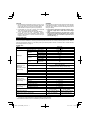
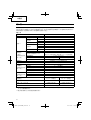
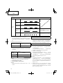
SPECIFICATIONS
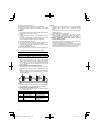
Although this machine includes 20 operation modes, up to four of them can be switched using the mode selection switch.
Four modes that are suitable for commonly performed operations have been set as factory default operation mode. With an
optional communication adaptor, you can freely select your desired operation modes. For
details, refer to "Mode selection
and rewriting functions" on page 10.
POWER TOOL
Model WM10DBL
Battery type BCL1015 BCL1030M
Capacity *1
Electronic pulse mode
Wood screw ø3.8 × 50 mm
Bolt mode
Ordinary bolt M4 – M8
High-strength bolt
M4 – M6
Self drilling screw mode
Small drilling screw
ø5
Drill mode
Woodwork drilling
ø12
Steel drilling ø5
Mortar drilling ø6
Electronic clutch
mode
*2
Small screw M6
Tightening torque
(Maximum)
[when fully charged
at 20°C temp]
Electronic pulse mode 19 N·m {194 kgf·cm}
Bolt mode [Tightening time: 3 sec.]
20 N·m {204 kgf·cm}
[Tightening is M8 high-strength bolt
(strength grade 12.9) Hexagon socket used]
Self drilling screw mode 14 N·m {143 kgf·cm}
Drill mode 1.6 N·m {16 kgf·cm} 2.5 N·m {25 kgf·cm}
Electronic clutch
mode *2 10-point clutch 1 – 6 N·m {10 – 61 kgf·cm}
Edge shape Width across fl at 6.35, bit insertion shape
Type of motor DC motor
No-load speed
[when fully charged
at 20°C temp]
Electronic pulse mode 0 – 2200 /min
Bolt mode 0 – 1300 /min
Self drilling screw mode 0 – 2200 /min
Drill mode 0 –
2200 /min
Electronic clutch mode *2 0 – 1140 /min
Number of blows
[when fully charged
at 20°C temp]
Electronic pulse mode 0 – 1090 /min
Bolt mode 0 – 1030 /min
Self drilling screw mode 0 – 1090 /min
Rechargeable battery
BCL1015: Li-ion 10.8 V
(1.5 Ah, 3 cells)
BCL1030M: Li-ion 10.8 V
(3.0 Ah, 6 cells)
Dimensions of the tool
Entire length × height × center height
139 mm × 216 mm × 29 mm
(BCL1015 attached)
139 mm × 233 mm × 29 mm
(BCL1030M attached)
Weight 1.0 kg (BCL1015 attached)
1.2 kg (BCL1030M attached)
LED light White LED
*1: The machine capability of BCL1015 becomes lower than that of BCL1030M in a high-load operation, because both
machines are of the same battery voltage but diff er in internal structure.
*2: The Electronic clutch mode is not of the factory default operation mode.
CAUTION
1. If liquid leaking
from the battery gets into your eyes, do not
rub your eyes and wash them well with fresh clean water
such as tap water and contact a doctor immediately.
If left untreated, the liquid may cause eye-problems.
2. If liquid leaks onto your skin or clothes, wash well with
clean water
such as tap water immediately.
There is a possibility that this can cause skin irritation.
3. If you fi nd rust, foul odor, overheating, discolor,
deformation, and/or other irregularities when using the
battery for the fi rst time, do not use and return it to your
supplier or vendor.

8
3. Drill chuck adapter set: Code No. 321823
Use drill bits available on the local market.
Optional accessories are subject to change without notice.
APPLICATIONS
○ Driving and removing of small screws, small bolts,
machine screws, wood screws, tapping screws, etc.
○ Drilling of various woods.
○ Drilling of various metals.
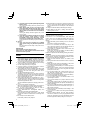
BATTERY REMOVAL/INSTALLATION
1. Battery removal
Hold the handle tightly and push the battery latch to
remove the battery (see Figs. 1 and 2).
CAUTION:
Never short-circuit the battery.
2. Battery installation
Insert the battery while observing its polarities (see
Fig. 2).
CHARGING
Before using the Electronic Pulse Driver, charge the battery
as follows.
1. Connect the charger power cord to the receptacle
When connecting the plug of the charger to a receptacle,
the pilot lamp will blink in red (At 1-second intervals).
2. Insert the battery into the charger
Firmly insert the battery into
the charger till it contacts the
bottom of the charger as shown in Fig. 3.
3. Charging
When inserting a battery in the charger, the pilot lamp will
light up continuously in red.
When the battery becomes fully recharged, the pilot lamp
will blink in red (At 1-second intervals). (See Table
1)
(1) Pilot lamp indication
The indications of the pilot lamp will be as shown in
Table 1, according to the condition of the charger or the
rechargeable battery.
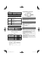
CHARGER
Model UC10SFL
Charging voltage 10.8 V
Weight 0.35 kg
STANDARD ACCESSORIES
In addition to the main unit (1), the package contains the
accessories listed in the table below.
WM10DBL
(2LCSK)
1Charger (UC10SFL) . .............................1
2Battery (BCL1015) ................................2
3Plastic case . ..........................................1
4Battery cover .. .......................................1
WM10DBL
(2LMSK)
1Charger (UC10SFL) . .............................1
2Battery (BCL1030M) .............................2
4Plastic case . ..........................................1
4Battery cover .. .......................................1
WM10DBL
(NN)
Without charger, battery, plastic case and
battery cover.
Standard accessories are subject to change without notice.
OPTIONAL ACCESSORIES (sold separately)
1. Plus driver bit
Bit No. Code No.
No. 2 992671
No. 3 992672
2. Hexagonal socket
Part Name
Engraved
characters
LB
Code
No.
5 mm Hexagonal socket 8 65 8 996177
6 mm Hexagonal socket 10 65 10 985329
5/16" Hexagonal socket 12 65 12 996178
8 mm Hexagonal socket 13 65 13 996179
Engraved characters

9
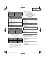
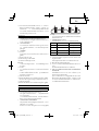
Table 1
Indications of the pilot lamp
Pilot lamp
(red)
Before
charging
Blinks
Lights for 0.5 seconds. Does not light for 0.5
seconds. (off for 0.5 seconds)
While
charging
Lights
Lights continuously
Charging
complete
Blinks
Lights for 0.5 seconds. Does not light for 0.5
seconds. (off for 0.5 seconds)
Overheat
standby
Blinks
Lights for 1 second. Does not light for 0.5
seconds. (off for 0.5 seconds)
Battery overheated.
Unable to charge
(Charging will commence
when battery cools).
Charging
impossible
Flickers
Lights for 0.1 second. Does not light for 0.1
seconds. (off for 0.1 seconds)
Malfunction in the battery or
the charger.
(2) Regarding the temperatures of the rechargeable battery
The temperatures for rechargeable batteries are as
shown in the Table 2, and batteries that have become
hot should be cooled for a while before being recharged.
Table 2 Recharging ranges of batteries
Rechargeable batteries
Temperatures at which the
battery can be recharged
BCL1015, BCL1030M 0°C – 50°C
(3) Regarding recharging time
Depending on the combination of the charger and
batteries, the charging time will become as shown in
Table 3.
Table 3 Charging time (At 20°C)
Charger
Battery
UC10SFL
BCL1015 Approx. 40 min.
BCL1030M Approx. 80 min.
NOTE
The charging time may vary according to temperature
and power source voltage.
4. Disconnect the charger’s power cord from the
receptacle.
5. Hold the charger fi rmly and pull out the battery.
NOTE
Be sure to pull out the battery from the charger after use,
and
then keep it.
Regarding electric discharge in case of new batteries, etc.
As the internal chemical substance of new batteries and
batteries that have not been used for an extended period
is not activated, the electric discharge might be low when
using them the fi rst and second time. This is a temporary
phenomenon, and normal time required for recharging
will be restored
by recharging the batteries 2 – 3 times.
How to make the batteries perform longer
(1) Recharge the batteries before they become completely
exhausted.
When you feel that the power of the tool becomes
weaker, stop using the tool and recharge its battery. If
you continue to use the tool and exhaust the electric
current, the battery may be
damaged and its life will
become shorter.
(2) Avoid recharging at high temperatures.
A rechargeable battery will be hot immediately after use.
If such a battery is recharged immediately after use, its
internal chemical substance will deteriorate, and the
battery life will be shortened. Leave the battery and
recharge it after
it has cooled for a while.
CAUTION
○ If the battery is charged while it is heated because it has
been left for a long time in a location subject to direct
sunlight or because the battery has just been used, the
pilot lamp of the charger lights for 1 second, does
not
light for 0.5 seconds (off for 0.5 seconds).
In such a case, fi rst let the battery cool, then start
charging.
○ When the pilot lamp fl ikers (at 0.2-second intervals),
check for and take out any foreign objects in the charger’s
battery connector. If there are no foreign objects, it is
probable that the battery or charger is malfunctioning.
Take it to your authorized Service Center.
○ Since the built-in micro computer takes about 3 seconds
to confi rm that the battery being charged with UC10SFL
is taken out, wait for a minimum of 3 seconds before
reinserting it to continue charging.
If the battery is
reinserted within 3 seconds, the battery may not be
properly charged.
PRIOR TO OPERATION
1. Preparing and checking the work environment
Make sure that the work site meets all the conditions laid
forth in the precautions.
2. Checking the battery
Make sure that the battery is installed fi rmly. If it is at all
loose it could come off and cause an accident.
3. Installing the
bit
○ Driver bit
Always follow the following procedure to install driver bit.
(Fig. 4)

10
(1) Pull the guide sleeve back.
(2) Insert the bit into the hexagonal hole in the anvil.
(3) Release the guide sleeve and it returns to its original
position.
CAUTION:
If the guide sleeve does not return to its original position,
then the bit is not installed properly.
○ Drill bit
• A
drill with hexagonal shank can be attached directly to
the tool.
• To attach a drill without hexagonal shank, you need to
have the drill chuck adapter set sold separately.
(1) Insert the drill bit into the chuck.
(2) Use the chuck key to secure the drill bit, tightening the
chuck
by each of the three holes in turn. (Fig. 5)
• Use an iron drill to make a pilot hole for a wood screw or
a 10 mm or smaller hole.
(1) Insert the drill bit into the chuck.
(2) Use the chuck key to secure the drill bit, tightening
the
chuck by each of the three holes in turn. (Fig. 5)
HOW TO USE
How to make the batteries perform longer
○ Recharge the batteries before they become completely
exhausted.
When you feel that the power of the tool becomes
weaker, stop using the tool and recharge its battery. If
you continue to use the tool and exhaust the electric
current, the battery may be
damaged and its life will
become shorter.
1. Mode selection and rewriting functions
The operation mode is switched each time you press the
mode selection switch provided on the side of the tool
body.
Select an operation mode corresponding to your desired
operation (Fig. 6).
NOTE:
The mode selection can be switched only after installing
the charger to the body and once pulling the switch.
(1) Default setting for operation mode
The following four modes are set as default operation
mode on this machine.
Symbol Operation mode
Example of applicable operation
A
Electronic pulse "3"
Tightening of wood screws
B Bolt "Continuous" Tightening of bolts
C Self drilling screw "2"
Tightening of
self drilling screw
D Drill Drilling
NOTE:
○ The tightening torque obtained in an actual tightening
operation varies with the screw or clamping member
used.
Try to tighten a few screws to confi rm the appropriate
tightening torque.
○ Use the Bolt mode to tighten
bolts.
○ Mode switching is impossible if the mode selection
switch is operated with the switch turned on. Be sure to
turn off the switch before performing mode switching.
(2) Built-in operation modes and mode rewriting
function of this product
The machine includes 20 operation modes in total. The
setting of
each mode is described below.
You can freely select up to four operation modes by using
an optional communication adaptor. It is also possible to
limit the number of switchable modes to one or two, or to
set all of the four modes to a same operation mode.

11
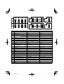
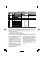
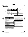
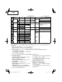
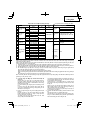
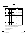
List of built-in operation modes means default operation mode.
No.
Operation mode
Maximum
torque
No-lode
speed
Number of
blows
Application
1
Electronic
pulse mode
1
13 N·m {133 kgf·cm}
0 – 1300 /min
1090
/min
Wood screw
tightening
Tightening screw shorter than 32 mm
22
19 N·m {194 kgf·cm}
0 – 2200 /min
1050
/min
Tightening of 32 – 50 mm screw
33
Tightening of 50 mm screw
4
Bolt mode *1
1
10 N·m {102 kgf·cm}
0 – 770 /min
1030
/min
Bolt
tightening
Ordinary bolt : M4 – M8
High-strength bolt : M4 – M6
52
15 N·m {153 kgf·cm}
0 – 1040 /min
63
20 N·m {204 kgf·cm}
0 – 1300 /min
7
Continuous
20 N·m {204 kgf·cm}
8
Self drilling
screw mode *2
1
3.5 N·m {36 kgf·cm}
0 – 2200 /min
1090
/min
Self drilling
screw tightening
ø3.5
92
14 N·m {143 kgf·cm}
ø4 – ø5
10
Drill mode *3
–––
1.6 N·m {16 kgf·cm}
2.5 N·m {25 kgf·cm}
0 – 2200 /min
–––
Drilling Wood ø12, Metal ø5, Mrotar ø6
11
Electronic
clutch
mode *4
1
1 N·m {10 kgf·cm}
0 – 250 /min
Tightening
machine
screw
Tightening
tapping
screw
Fixing of
gypsum
board
– M6
12 2
1.4 N·m {14 kgf·cm}
0 – 350 /min
13 3
1.8 N·m {18 kgf·cm}
0 – 450 /min
14 4
2.3 N·m {23 kgf·cm}
0 – 550 /min
15 5
2.8 N·m {29 kgf·cm}
0 – 650 /min
16 6
3.3 N·m {34 kgf·cm}
0 – 750 /min
17 7
3.9 N·m {40 kgf·cm}
0 – 850 /min
18 8
4.6 N·m {47 kgf·cm}
0 – 950 /min
19 9
5.3 N·m {54 kgf·cm}
0 – 1040 /min
20 10
6 N·m {61 kgf·cm}
0 – 1140 /min
The maximum torque in the list is the set maximum torque that is generated by the tool itself in a selected operation mode.
The tightening torque obtained in an actual tightening operation varies with the screw or clamping member used. Therefore,
you need to try to tighten a few screws for
confi rmation.
*1: The Bolt mode 1, 2, and 3 are to be stopped by ten times of striking for accuracy improvement of tightening torque.
*2: Before fi xing a thin plate with a self drilling screw, make sure that the thickness of the plate is suitable for the screw
diameter.
*3: When
installing BCL1015: 1.6 N·m {16 kgf·cm}, When installing BCL1030M: 2.5 N·m {25 kgf·cm}
*4: With the electronic clutch mode 4
–
10 the tool may execute reverse rotation briefl y when the load increases in order to
reduce a risk of screw-head damage.
The tool starts up in low rotation speed and tightens softly.
The motor automatically stops rotating when the torque reaches to the pre-set value in order to reduce over
tightening.
The clutch sound such as of the mechanical type will not be generated.
You can change the switchable operation modes with the dedicated software by connecting the communication adaptor
between the tool and PC.
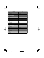
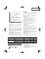
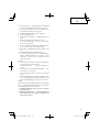
2. Characteristics of Electronic Pulse Driver
Unlike a conventional impact driver, the electronic pulse
driver generates
the striking force by rotating the motor in
regular and reverse directions repeatedly.
This mechanism has helped to provide quieter operation.
The following characteristics are uncommon to a
conventional impact driver, however these are not signs
of malfunction.
○ The tool tends to be heated by continuous screw
tightening.
To protect
the motor and electronic parts that control the
motor operation, this tool is equipped with a temperature
protection circuit.
Depending on the screw and material being screwed, the
striking operation may start early.
Since the striking operation causes temperature increase
of the motor and electronic parts, the temperature
protection circuit
may be activated early.
Refer to "1. Continuous operation" on page 13 for
recovering from the operation stop caused by the
temperature protection circuit.
Also, the electronic pulse driver controls the motor
rotation consistently to provide the optimum operation for
each mode.
Because of this, the following cases can occur during
operation.
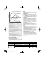
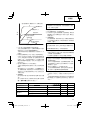
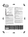
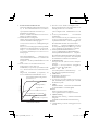
○ The behavior at operation start diff ers by the mode.
The self drilling screw mode (1) gradually increases the
speed.
The electronic clutch mode (regular rotation) rotates the
motor at a very slow speed for a certain period after the
start and then increases the speed.
On the
other hand, the electronic clutch mode (reverse
rotation) meets the preset rotation speed immediately
after the start.

12
Electronic pulse mode, self drilling screw
mode (2) and drill mode
Self drilling screw
mode (1)
Bolt mode
Electronic clutch mode
(reverse rotation)
Electronic clutch mode
(regular rotation)
Rotation speed
Elapsed time after switching on
○ The tool may not return to the initial status from the
striking operation.
When the bit or socket is removed from the screw or bolt
while the switch is being pulled, the tool may continue the
striking operation.
To return to the initial status, turn
off the switch and then
start the next operation.
○ Motor rotation speed does not decrease even when the
remaining battery power becomes low.
Since this tool adopts the constant-speed control, the
rotation speed is almost unchanged even when the
remaining amount of the battery becomes low. This
allows users to
operate the tool effi ciently until the battery
runs down. However, it is diffi cult to know the remaining
battery power from the rotation speed and the tool may
stop suddenly during work.
○ The tool stops automatically when the electronic clutch is
actuated.
Quiet screw tightening can be performed
without clutch
sound generated by the mechanical type.
The tool stops automatically when the clutch is actuated.
If you continue to use the tool, turn off the switch once
and turn it on again. When the tool does not operate even
without load, the remaining amount of the battery is
low.
In this case, recharge the battery immediately.
3. Check the rotational direction
The bit rotates clockwise (viewed from the rear side) by
pushing the R-side of the push button.
The L-side of the push button is pushed to turn the bit
counterclockwise. (See Fig. 7) (The
and marks
are provided on the body.)
CAUTION:
The push button can not be switched while the tool is
turning. To switch the push button, stop the tool, then set
the push button.
4. Switch operation
○ When the trigger switch is depressed, the tool rotates.
When the trigger is released, the tool
stops.
○ The rotational speed can be controlled by varying the
amount that the trigger switch is pulled. Speed is low
when the trigger switch is pulled slightly and increases as
the trigger switch is pulled more.
5. Using the light
Pull the trigger switch to light up the light. The
light keeps
on lighting while the trigger switch is being pulled. The
light goes out after releasing the trigger switch. (Fig. 8)
CAUTION:
Do not expose directly your eyes to the light by looking
into the light.
If your eyes are continuously exposed to the light, your
eyes will be
hurt.
6. Tightening and loosening screws
Install the bit that matches the screw, line up the bit in the
grooves of the head of the screw, then tighten it.
Push the tool just enough to keep the bit fi tting the head
of the screw.
CAUTION:
○ Applying the tool for too long tightens
the screw too much
and can break it.
Tightening a screw with the tool at an angle to that screw
can damage the head of the screw and the proper force
will not be transmitted to the screw.
Tighten with this tool lined up straight with the screw.
○ Use the
bit that fi ts the cross recess on the screw head.
Make sure to use an appropriate bit especially when
tightening self drilling screws since using an inappropriate
bit can topple the screws.
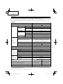
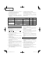
7. Work amount possible with one charging
The following table shows the approximate amount of
work to be carried
out by the tool with one charging.
(The number of screws tightened and that of boring
operations diff er slightly according to the hardness of
wood or metal, the ambient temperature, the charger
properties, etc.)
Operation mode Operation
Battery
BCL1015 BCL1030M
Electronic pulse mode [3]
Wood screw tightening ø3.8 × 50 Lauan Approx. 300 Approx. 700
Bolt mode [3] Bolt tightening M8 × 30 S10C Approx. 100 Approx. 240
Self drilling screw mode [2]
Self drilling screw tightening ø4 × 16
C-channel t2.3 + SPCC t1.6
Approx. 120 Approx. 280
Drill mode
Woodwork drilling ø12 American pine t18 Approx. 220 Approx. 510
Steel drilling ø5 SPCC t1.6 Approx. 95 Approx. 220
Electronic clutch mode Machine screw tightening M6 × 12 S10C Approx. 1670 Approx. 3900

13
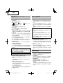
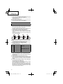
ABOUT BATTERY BCL1030M
1. Battery capacity indicator
<How to read the display>
Fig. 9-a When recharging, During pause
Fig. 9-b When using tools
(
: Lights, : Goes out, : Blinks, (2-second
period),
: Blinks rapidly (0.5-second period))
(1) When recharging (Fig. 10)
The indication lamps will blink and indicate the charging
amount to the battery.
(2) During pause (Fig. 11)
The indication lamps will always blink and indicate the
remaining capacity of the battery.
(3) When using tools (Fig. 12)
When
turning on the switch of the cordless tool, the
indication lamps will light and indicate the remaining
capacity of the battery. After three seconds or so from
releasing the switch, the indication lamps will start
blinking.
2. Protective function
In the following case 1 and case 2, the motor of the
cordless tool may stop (indication lamps are turned off )
during operation, however, this is not a sign of failure, but
is caused by activation of the protective function.
(1) The motor stops when the remaining battery capacity
becomes low (battery voltage decreased to 6V). In this
case, recharge the
battery promptly.
(2) The motor may stop when the cordless tool is overloaded.
In this case, release the switch and eliminate the cause of
the overload. After that, you can use the tool again.
3. Indication of trouble (Fig. 13)
When the indication lamps blink rapidly (0.5-second
period), it may suggest a
battery failure. Please take the
battery to the dealer you purchased from.
4. How to determine the battery usage life
When the operating time of the battery becomes
signifi cantly short after correctly recharging the battery,
it may indicate the end of the battery life and we
recommend you to purchase
a new battery.
NOTE:
If left unused for a long period, the battery may become
too weak to light up or blink the indication lamps used to
show the remaining power. The lamps will light back up
or blink once the battery is recharged.
Hints on how to make the battery last
(1) Recharge the Battery Before it Becomes Completely
Discharged.
When you feel that the power of the tool weakens, stop
using the tool and recharge the battery.
If you continue using the tool and discharge the battery,
the battery will be damaged and
its life will be shortened.
(2) Avoid Recharging the Battery at High Temperatures.
The battery will be hot immediately after using the tool.
If you recharge the battery too soon, the chemical
substances inside the battery will deteriorate, and the life
of the battery will be shortened.
Let the battery take
rest and cool down before recharging
it.
* If there is anything you do not understand about this
product, please feel free to inquire with your nearest
authorized Service Agent.
OPERATIONAL CAUTIONS
1. Continuous operation
When you perform the striking operation continuously,
the temperature protection circuit may be activated early.
(Refer to "2. Characteristics of Electronic Pulse Driver"
on page 11.)
When the activated temperature protection circuit stops
the tool, the LED light fl ashes to indicate that the tool
is heated to high
temperature. The LED light goes off
automatically after approx. 30 seconds.
When you perform continuous operation, allow the
tool to rest for around 15 minutes at a replacement of
rechargeable battery.
NOTE:
○ When the tool is stopped by the activated temperature
protection circuit, allow the tool to cool suffi
ciently.
You can use the tool again when it cools down.
○ While the tool is not cooled suffi ciently, it cannot start up
by turning the switch to on. The LED light fl ashes while
the switch is turned on. Please wait until the tool cools
down suffi ciently.
○
Do not touch the nose part of the tool during continuous
operation. It is heated to high temperature.
2. Cautions on use of the speed control switch
This switch has a built-in, electronic circuit which steplessly
varies the rotation speed. Consequently, when the switch
trigger is pulled only slightly (low speed
rotation) and the
motor is stopped while continuously driving in screws, the
components of the electronic circuit parts may overheat and
be damaged.
3. Holding the tool and applying the pressing force
Make sure to hold the tool securely with your both hands,
and keep the tool straight to a screw
or bolt. There is no
need to press the tool excessively against materials.
Be careful not to apply excessive pressing/prying force to
the tool. It may damage the tool.
MAINTENANCE AND INSPECTION
1. Inspecting the tool
Since use of a dull tool will degrade effi ciency and cause
possible motor malfunction, sharpen or replace the tool
as soon as abrasion is noted.
2. Inspecting the mounting screws
Regularly inspect all mounting screws and ensure that
they are properly tightened. Should any of the
screws be
loose, retighten them immediately. Failure to do so could
result in serious hazard.
3. Maintenance of the motor
The motor unit winding is the very "heart" of the power
tool.
Exercise due care to ensure the winding does not
become damaged and/or wet with oil or water.
4. Cleaning
of the outside
When the tool is stained, wipe with a soft dry cloth or a
cloth moistened with soapy water. Do not use chloric
solvents, gasoline or paint thinner, for they melt plastics.
5. Storage
Store the toolr in a place in which the temperature is less
than 40°C and
out of reach of children.
NOTE
Make sure that the battery is fully charged whenstored for
a long period (3 months or more). Thebattery with smaller
capacity may not be able to becharged when used, if
stored for a long period.

14
6. Service parts list
CAUTION:
Repair, modifi cation and inspection of Hitachi Power
Tools must be carried out by a Hitachi Authorized Service
Center.
This Parts List will be helpful if presented with the tool to
the Hitachi Authorized Service Center when requesting
repair or other maintenance.
In the operation and
maintenance of power tools, the
safety regulations and standards prescribed in each
country must be observed.
MODIFICATIONS
Hitachi Power Tools are constantly being improved
and modifi ed to incorporate the latest technological
advancements.
Accordingly, some parts may be changed without prior
notice.
Important notice on the batteries for the Hitachi
cordless power tools
Please always use one of our designated genuine batteries.
We cannot guarantee the safety and performance of
our cordless power tool when used with batteries other
than these designated by us, or when the battery is
disassembled and modifi ed
(such as disassembly and
replacement of cells or other internal parts).
NOTE
Due to HITACHI’s continuing program of research and
development, the specifi cations herein are subject to
change without prior notice.

15

16
○
○
○
○

17

18

19
1
2
3
4
1
2
3
4

20
ページが読み込まれています...
ページが読み込まれています...
ページが読み込まれています...
ページが読み込まれています...
ページが読み込まれています...
ページが読み込まれています...
ページが読み込まれています...
ページが読み込まれています...
ページが読み込まれています...
ページが読み込まれています...
ページが読み込まれています...
ページが読み込まれています...
ページが読み込まれています...
ページが読み込まれています...
ページが読み込まれています...
ページが読み込まれています...
ページが読み込まれています...
ページが読み込まれています...
ページが読み込まれています...
ページが読み込まれています...
ページが読み込まれています...
ページが読み込まれています...
ページが読み込まれています...
ページが読み込まれています...
ページが読み込まれています...
ページが読み込まれています...
ページが読み込まれています...
ページが読み込まれています...
ページが読み込まれています...
ページが読み込まれています...
ページが読み込まれています...
ページが読み込まれています...
ページが読み込まれています...
ページが読み込まれています...
ページが読み込まれています...
ページが読み込まれています...
ページが読み込まれています...
ページが読み込まれています...
ページが読み込まれています...
ページが読み込まれています...
-
 1
1
-
 2
2
-
 3
3
-
 4
4
-
 5
5
-
 6
6
-
 7
7
-
 8
8
-
 9
9
-
 10
10
-
 11
11
-
 12
12
-
 13
13
-
 14
14
-
 15
15
-
 16
16
-
 17
17
-
 18
18
-
 19
19
-
 20
20
-
 21
21
-
 22
22
-
 23
23
-
 24
24
-
 25
25
-
 26
26
-
 27
27
-
 28
28
-
 29
29
-
 30
30
-
 31
31
-
 32
32
-
 33
33
-
 34
34
-
 35
35
-
 36
36
-
 37
37
-
 38
38
-
 39
39
-
 40
40
-
 41
41
-
 42
42
-
 43
43
-
 44
44
-
 45
45
-
 46
46
-
 47
47
-
 48
48
-
 49
49
-
 50
50
-
 51
51
-
 52
52
-
 53
53
-
 54
54
-
 55
55
-
 56
56
-
 57
57
-
 58
58
-
 59
59
-
 60
60


Hitachi WM 10DBL Handling Instructions Manual
- カテゴリー
- パワーツール
- タイプ
- Handling Instructions Manual
関連論文
-
Hitachi WR18DSHL Handling Instructions Manual
-
-
Hitachi DS 10DAL Handling Instructions Manual
-
-
Hikoki BCL1030A ユーザーマニュアル
-
Hikoki DV18DL2 ユーザーマニュアル
-
-
-
Hikoki DV 14DBL ユーザーマニュアル
-
Hikoki DH 14DSL ユーザーマニュアル