
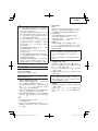
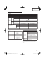
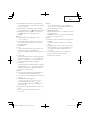
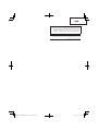
Cordless Impact Driver Drill
충전 임팩트 드라이버 드릴
Máy khoan vặn vít động lực dùng pin
DV14DBEL
•
DV18DBEL
Handling instructions Hướng dẫn sử dụng
취급 설명서
DV18DBEL
Read through carefully and understand these instructions before use.
본 설명서를 자세히 읽고 내용을 숙지한 뒤 제품을 사용하십시오.
Đọc kỹ và hiểu rõ các hướng dẫn này trước khi sử dụng.

2
12
3
45
678
5
3
4
2
1
2
8
1
BSL1440
BSL1430
BSL1840
BSL1830
BSL1820
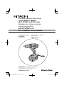
<UC18YRSL / UC18YML2> <UC18YFSL> <UC18YGSL>
^
(
*
&
^
t
6
7
(
)
!
0
#
@
1
9
$
w
e
UC18YML2
UC18YML2
UC18YML2
0
0
1
1
9
9
%
%
%
1
<UC18YRSL / UC18YML2> <UC18YGSL>
q
r
e

3
91011
12 13
i
o
p
a
d
s
f
u
y
u
y
f
o

4
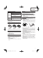
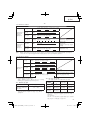
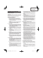
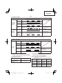
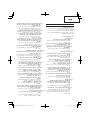
English
한국어
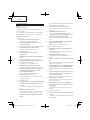
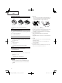
1
Rechargeable battery
충전식 배터리
2
Latch
래치
3
Battery cover
배터리 커버
4
Terminal
단자
5
Ventilator
통기구
6
Push
밀기
7
Pull out
잡아당김
8
Handle
핸들
9
Charger
충전기
0
Pilot lamp
파일럿 램프
!
Strap
스트랩
@
Connecting socket
연결 소켓
#
Charger connecting plug
충전기 연결 플러그
$
Cigarette lighter connecting plug
시가 라이터 연결 플러그
%
Line
라인
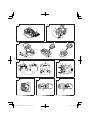
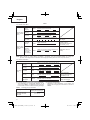
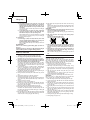
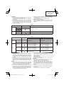
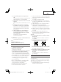
^
Drill mark 드릴 표시
&
Hammer mark
해머 표시
*
Clutch dial
클러치 다이얼
(
Triangle mark 삼각형 표시
)
Weak
약
q
Strong
강
w
Line
라인
e
Shift knob 변속 노브
r
Low speed
저속
t
High speed
고속
y
Screw
나사
u
Hook
후크
i
Groove
홈
o
Trigger switch
트리거 스위치
p
Sleeve
슬리브
a
Tighten
조임
s
Loosen
풀기
d
Selector button 선택 버튼
f
R
and
L
marks
R
L
R
및
L
표시

5
Tiếng Việt
1
Pin sạc
2
Chốt
3
Nắp pin
4
Đầu cuối
5
Quạt thông gió
6
Đẩy
7
Kéo ra
8
Cầm
9
Bộ sạc
0
Đèn báo
!
Dây đai
@
Ổ cắm nối điện
#
Phích cắm sạc
$
Phích cắm bật lửa
%
Dây dẫn
^
Dấu hiệu khoan
&
Dấu hiệu búa
*
Quay số ly hợp
(
Dấu hiệu tam giác
)
Yếu
q
Mạnh
w
Dây dẫn
e
Tay nắm dịch chuyển
r
Tốc độ thấp
t
Tốc độ cao
y
Vít
u
Móc treo
i
Khe lắp
o
Công tắc khởi động
p
Ống bọc ngoài
a
Siết chặt
s
Nới lỏng
d
Nút chọn
f
Dấu hiệu
R
và
L
R
L
L
R

English
6
GENERAL SAFETY RULES
WARNING!
Read all instructions
Failure to follow all instructions listed below may result in
electric shock, fi re and/or serious injury.
The term “power tool” in all of the warnings listed below
refers to your mains operated (corded) power tool or battery
operated (cordless) power tool.
SAVE THESE INSTRUCTIONS
1) Work area
a) Keep work area clean and well lit.
Cluttered and dark areas invite accidents.
b) Do not operate power tools in explosive
atmospheres, such as in the presence of
fl ammable liquids, gases or dust.
Power tools create sparks which may ignite the dust
or fumes.
c) Keep children and bystanders away while
operating a power tool.
Distractions can cause you to lose control.
2) Electrical safety
a) Power tool plugs must match the outlet.
Never modify the plug in any way.
Do not use any adapter plugs with earthed
(grounded) power tools.
Unmodifi ed plugs and matching outlets will reduce
risk of electric shock.
b) Avoid body contact with earthed or grounded
surfaces such as pipes, radiators, ranges and
refrigerators.
There is an increased risk of electric shock if your
body is earthed or grounded.
c) Do not expose power tools to rain or wet
conditions.
Water entering a power tool will increase the risk of
electric shock.
d) Do not abuse the cord. Never use the cord for
carrying, pulling or unplugging the power tool.
Keep cord away from heat, oil, sharp edges or
moving parts.
Damaged or entangled cords increase the risk of
electric shock.
e) When operating a power tool outdoors, use an
extension cord suitable for outdoor use.
Use of a cord suitable for outdoor use reduces the
risk of electric shock.
3) Personal safety
a) Stay alert, watch what you are doing and use
common sense when operating a power tool.
Do not use a power tool while you are tired
or under the infl uence of drugs, alcohol or
medication.
A moment of inattention while operating power tools
may result in serious personal injury.
b) Use safety equipment. Always wear eye
protection.
Safety equipment such as dust mask, non-skid
safety shoes, hard hat, or hearing protection used for
appropriate conditions will reduce personal injuries.
c) Avoid accidental starting. Ensure the switch is in
the off position before plugging in.
Carrying power tools with your fi nger on the switch or
plugging in power tools that have the switch on invites
accidents.
d) Remove any adjusting key or wrench before
turning the power tool on.
A wrench or a key left attached to a rotating part of the
power tool may result in personal injury.
e) Do not overreach. Keep proper footing and
balance at all times.
This enables better control of the power tool in
unexpected situations.
f) Dress properly. Do not wear loose clothing or
jewellery. Keep your hair, clothing and gloves
away from moving parts.
Loose clothes, jewellery or long hair can be caught in
moving parts.
g) If devices are provided for the connection of
dust extraction and collection facilities, ensure
these are connected and properly used.
Use of these devices can reduce dust related
hazards.
4) Power tool use and care
a) Do not force the power tool. Use the correct
power tool for your application.
The correct power tool will do the job better and safer
at the rate for which it was designed.
b) Do not use the power tool if the switch does not
turn it on and off .
Any power tool that cannot be controlled with the
switch is dangerous and must be repaired.
c) Disconnect the plug from the power source
before making any adjustments, changing
accessories, or storing power tools.
Such preventive safety measures reduce the risk of
starting the power tool accidentally.
d) Store idle power tools out of the reach of children
and do not allow persons unfamiliar with the
power tool or these instructions to operate the
power tool.
Power tools are dangerous in the hands of untrained
users.
e) Maintain power tools. Check for misalignment or
binding of moving parts, breakage of parts and
any other condition that may aff
ect the power
tools’ operation.
If damaged, have the power tool repaired before
use.
Many accidents are caused by poorly maintained
power tools.
f) Keep cutting tools sharp and clean.
Properly maintained cutting tools with sharp cutting
edges are less likely to bind and are easier to control.
g) Use the power tool, accessories and tool bits
etc., in accordance with these instructions and
in the manner intended for the particular type
of power tool, taking into account the working
conditions and the work to be performed.
Use of the power tool for operations diff erent from
intended could result in a hazardous situation.
5) Battery tool use and care
a) Ensure the switch is in the off position before
inserting battery pack.
Inserting the battery pack into power tools that have
the switch on invites accidents.
b) Recharge only with the charger specifi ed by the
manufacturer.
A charger that is suitable for one type of battery pack
may create a risk of fi re when used with another
battery pack.
c) Use power tools only with specifi cally designated
battery packs.
Use of any other battery packs may create a risk of
injury and fi re.

English
7
d) When battery pack is not in use, keep it away
from other metal objects like paper clips, coins,
keys, nails, screws, or other small metal objects
that can make a connection from one terminal to
another.
Shorting the battery terminals together may cause
burns or a fi re.
e) Under abusive conditions, liquid may be ejected
from the battery; avoid contact. If contact
accidentally occurs, fl ush with water. If liquid
contacts eyes, additionally seek medical help.
Liquid ejected from the battery may cause irritation or
burns.
6) Service
a) Have your power tool serviced by a qualifi ed
repair person using only identical replacement
parts.
This will ensure that the safety of the power tool is
maintained.
PRECAUTION
Keep children and infi rm persons away.
When not in use, tools should be stored out of reach of
children and infi rm persons.
CORDLESS IMPACT DRIVER DRILL SAFETY
WARNINGS
1. Wear ear protectors when impact drilling.
Exposure to noise can cause hearing loss.
2. Use auxiliary handle(s), if supplied with the tool.
Loss of control can cause personal injury.
3. Hold power tool by insulated gripping surfaces,
when performing an operation where the cutting
accessory or fastener may contact hidden wiring.
Cutting accessory or fasteners contacting a “live” wire
may make exposed metal parts of the power tool “live”
and could give the operator an electric shock.
4. Always charge the battery at
a temperature of 0°C –
40°C. A temperature of less than 0°C will result in over
charging which is dangerous. The battery cannot be
charged at a temperature higher than 40°C.
The most suitable temperature for charging is that of
20°C – 25°C.
5. When one charging is completed, leave the
charger for
about 15 minutes before the next charging of battery.
Do not charge more than two batteries consecutively.
6. Do not allow foreign matter to enter the hole for
connecting the rechargeable battery.
7. Never disassemble the rechargeable battery and
charger.
8. Never short-circuit the rechargeable battery. Short-
circuiting the battery
will cause a great electric current
and overheat. It results in burn or damage to the battery.
9. Do not dispose of the battery in fi re.
If the battery is burnt, it may explode.
10. Bring the battery to the shop from which it was purchased
as soon as the post-charging battery
life becomes too
short for practical use. Do not dispose of the exhausted
battery.
11. Using an exhausted battery will damage the charger.
12. Do not insert object into the air ventilation slots of the
charger.
Inserting metal objects or infl ammables into the charger
air ventilation slots will result in
electrical shock hazard or
damaged charger.
13. When mounting a bit into the keyless chuck, tighten the
sleeve adequately. If the sleeve is not tight, the bit may
slip or fall out, causing injury.
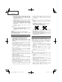
14. This product contains a strong permanent magnet in the
motor.
Observe the following precautions regarding adhering of
chips to the tool and the eff ect of the permanent magnet
on electronic devices.
CAUTION
○ Do not place the tool on a workbench or work area
where metal chips are present.
The chips may adhere to the tool, resulting in injury or
malfunction.
○ If chips have adhered to the tool, do not touch it.
Remove the chips with a brush.
Failure to
do so may result in injury.
○ If you use a pacemaker or other electronic medical
device, do not operate or approach the tool.
Operation of the electronic device may be aff ected.
○ Do not use the tool in the vicinity of precision
devices such as cell phones, magnetic cards or
electronic memory media.
Doing so may lead to misoperation, malfunction or loss of
data.
CAUTION ON LITHIUM-ION BATTERY
To extend the lifetime, the lithium-ion battery equips with the
protection function to stop the output.
In the cases of 1 to 3 described below, when using this
product, even if you are pulling the switch, the motor may
stop. This is not the trouble but the result of protection
function.
1.
When the battery power remaining runs out, the motor
stops.
In such case, charge it up immediately.
2. If the tool is overloaded, the motor may stop. In this
case, release the switch of tool and eliminate causes of
overloading. After that, you can use it again.
3. If the battery is
overheated under overload work, the
battery power may stop.
In this case, stop using the battery and let the battery
cool. After that, you can use it again.
Furthermore, please heed the following warning and caution.
WARNING
In order to prevent any battery leakage, heat generation,
smoke emission, explosion and ignition beforehand,
please
be sure to heed the following precautions.
1. Make sure that swarf and dust do not collect on the
battery.
○ During work make sure that swarf and dust do not fall on
the battery.
○ Make sure that any swarf and dust falling on the power
tool during work do
not collect on the battery.
○ Do not store an unused battery in a location exposed to
swarf and dust.
○ Before storing a battery, remove any swarf and dust that
may adhere to it and do not store it together with metal
parts (screws, nails, etc.).
2. Do not pierce battery
with a sharp object such as a
nail, strike with a hammer, step on, throw or subject the
battery to severe physical shock.
3. Do not use an apparently damaged or deformed battery.
4. Do not use the battery in reverse polarity.
5. Do not connect directly to an electrical outlets or
car
cigarette lighter sockets.

English
8
6. Do not use the battery for a purpose other than those
specifi ed.
7. If the battery charging fails to complete even when a
specifi ed recharging time has elapsed, immediately stop
further recharging.
8. Do not put or subject the battery to high temperatures or
high pressure such as into
a microwave oven, dryer, or
high pressure container.
9. Keep away from fi re immediately when leakage or foul
odor are detected.
10. Do not use in a location where strong static electricity
generates.
11. If there is battery leakage, foul odor, heat generated,
discolored or deformed, or in any way appears abnormal
during use, recharging or storage, immediately remove it
from the equipment or battery charger, and stop use.
CAUTION
1. If liquid leaking from the battery gets into your eyes, do not
rub your eyes and wash them well with fresh clean water
such as tap water and contact a doctor immediately.
If
left untreated, the liquid may cause eye-problems.
2. If liquid leaks onto your skin or clothes, wash well with
clean water such as tap water immediately.
There is a possibility that this can cause skin irritation.
3. If you fi nd rust, foul odor, overheating, discolor,
deformation, and/or other irregularities when using
the
battery for the fi rst time, do not use and return it to your
supplier or vendor.
WARNING
If a conductive foreign matter enters in the terminal of lithium
ion battery, the battery may be shorted, causing fi re. When
storing the lithium ion battery, obey surely the rules of
following contents.
○ Do not place conductive debris, nail and wires such
as iron wire and copper wire in the storage case.
○ To prevent shorting from occurring, load the battery
in the tool or insert securely the battery cover for
storing until the ventilator is not seen.
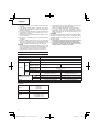
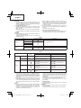
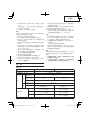
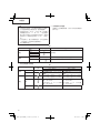
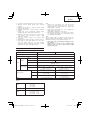
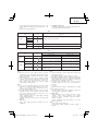
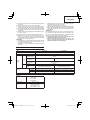
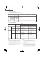
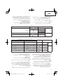
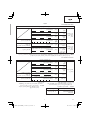
SPECIFICATIONS
POWER TOOL
Model DV14DBEL DV18DBEL
No-load speed (Low/High) 0 – 400 / 0 – 1500 /min
No-load impact rate (Low/High) 0 – 5600 / 0 – 21000 /min
Capacity
Drilling
Brick
(Depth 30 mm)
13 mm
Wood
(Thickness 18 mm)
36 mm 38 mm
Metal
(Thickness 1.6 mm)
Steel: 13 mm
Aluminum: 13 mm
Driving
Machine screw 6 mm
Wood screw
6.8 mm (diameter) × 50 mm (length)
(Requires a pilot hole)
8 mm (diameter) × 75 mm (length)
(Requires a pilot hole)
Rechargeable battery
2LLRK BSL1440: Li-ion 14.4 V (4.0 Ah 8 cells) BSL1840: Li-ion 18 V (4.0 Ah 10 cells)
2LSRK BSL1430: Li-ion 14.4 V (3.0 Ah 8 cells) BSL1830: Li-ion 18 V (3.0 Ah 10 cells)
2LBGK ― BSL1820: Li-ion 18 V (2.0 Ah 5 cells)
Weight
1.8 kg (BSL1440 attached) 1.9 kg (BSL1840 attached)
CHARGER
Model
UC18YRSL
UC18YFSL
UC18YGSL
UC18YML2
Charging voltage 14.4 V ― 18 V
Weight
UC18YRSL: 0.6 kg
UC18YFSL: 0.5 kg
UC18YGSL: 0.4 kg
UC18YML2: 0.7 kg

English
9
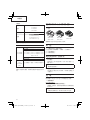
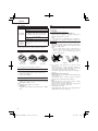
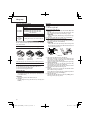
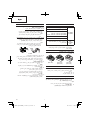
STANDARD ACCESSORIES
DV14DBEL
DV18DBEL
1
Plus driver bit (No. 2) .......................... 1
2
Charger .............................................. 1
3
Battery ................................................ 2
[DV14DBEL] BSL1440 or BSL1430
[DV18DBEL] BSL1840 or BSL1830 or
BSL1820
4
Plastic case ........................................ 1
5
Battery cover ...................................... 1
DV14DBEL
(NN)
DV18DBEL
(NN)
Without charger, battery, plastic case and
battery cover.
Standard accessories are subject to change without notice.
The charger and battery supplied
are diff erent depending on
the set specifi cation.
OPTIONAL ACCESSORIES (sold separately)
1. Battery
(BSL1430)
(BSL1440)
(BSL1830)
(BSL1840)
(BSL1820)
Optional accessories are subject to change without notice.
APPLICATIONS
○ Drilling of brick and concrete block, etc.
○ Driving and removing of machine screws, wood screws,
tapping screws, etc.
○ Drilling of various metals.
○ Drilling of various woods.
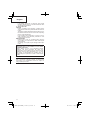
BATTERY REMOVAL/INSTALLATION
1. Battery removal
Hold the handle tightly and push the battery latches (2
pcs.) to remove the battery (see Figs. 1 and 2).
CAUTION
Never short-circuit the battery.
2. Battery installation
Insert the battery while observing its polarities (see
Fig. 2).
CHARGING
Before using the power tool, charge the battery as follows.
1. Connect to the power source
When charging the battery from an AC power source
○ Connect the charger’s power cord to the receptacle.
When connecting the plug of the charger to a receptacle,
the pilot lamp will blink in red (At 1-second intervals).
CAUTION
Do not use the electrical cord if damaged. Have it
repaired
immediately.
When charging the battery from a DC 12V in-car power
source (UC18YML2)
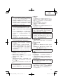
○ Secure the battery charger in place in the car.
Use the strap supplied with the battery charger to fasten
the battery charger in place and prevent it from moving
inadvertently. (See Fig. 14)
CAUTION
Do not place the battery
charger or battery under the
driver’s seat. Secure the battery charger in place to
prevent it from moving inadvertently as this may lead to
an accident.
Fig. 14
○ Insert the cigarette lighter connecting plug into the
cigarette lighter socket.
If the plug is loose and falls out of the cigarette lighter
socket, repair the socket. As the socket may be faulty,
you are recommended to contact your local car dealer.
Continued use of the socket may result
in an accident
due to overheating.
2. Insert the battery into the charger
Firmly insert the battery into the charger until the line is
visible, as shown in Fig. 3, 4.
Lines are not displayed on the UC18YFSL. Make sure
that the battery is set fi rmly in place.
3. Charging
When inserting a battery in the charger, charging will
commence and
the pilot lamp will light up continuously in
red.
When the battery becomes fully recharged, the pilot lamp
will blink in red (At 1-second intervals). (See Table 1)
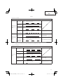
(1) Pilot lamp indication
The indications of the pilot lamp will be as shown in
Table 1, according to the condition of the charger
or the
rechargeable battery.

English
10
Table 1
<UC18YRSL/UC18YML2>
Indications of the pilot lamp
The pilot lamp
lights or blinks
in red.
Before
charging
Blinks
Lights for 0.5 seconds. Does not light for 0.5
seconds. (off for 0.5 seconds)
While
charging
Lights
Lights continuously
Charging
complete
Blinks
Lights for 0.5 seconds. Does not light for 0.5
seconds. (off for 0.5 seconds)
Charging
impossible
Flickers
Lights for 0.1 second. Does not light for 0.1
seconds. (off for 0.1 seconds)
Malfunction in the battery or
the charger.
The pilot lamp
lights or blinks
in green.
Overheat
standby
Lights
Lights continuously
Battery overheated.
Unable to charge
(Charging will commence
when battery cools).
Charging
with in-car
power source
impossible
(UC18YML2)
Blinks
Lights for 0.5 seconds. Does not light for 0.5
seconds. (off for 0.5 seconds)
Malfunction of the car
battery
NOTE: When standby for cooling battery, UC18YML2 / UC18YRSL cools the overheated battery by cooling fan.
(However, the cooling fan does not function when charging the battery with a DC 12V in-car power source.)
<UC18YFSL/UC18YGSL>
Indications of the pilot lamp
Pilot lamp
(red)
Before
charging
Blinks
Lights for 0.5 seconds. Does not light for 0.5
seconds. (off for 0.5 seconds)
While
charging
Lights
Lights continuously
Charging
complete
Blinks
Lights for 0.5 seconds. Does not light for 0.5
seconds. (off for 0.5 seconds)
Overheat
standby
Blinks
Lights for 1 second. Does not light for 0.5
seconds. (off for 0.5 seconds)
Battery overheated.
Unable to charge.
(Charging will commence
when battery cools)
Charging
impossible
Flickers
Lights for 0.1 second. Does not light for 0.1
seconds. (off for 0.1 seconds)
Malfunction in the
battery or the charger
(2) Regarding the temperatures of the rechargeable battery
The temperatures for rechargeable batteries are as
shown in the Table 2, and batteries that have become
hot should be cooled for a while before being recharged.
Table 2 Recharging ranges of batteries
Rechargeable batteries
Temperatures at which the
battery can be recharged
BSL1430, BSL1440
BSL1820, BSL1830,
BSL1840
0°C – 40°C
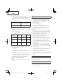
(3) Regarding recharging time
Depending on the combination of the charger and
batteries, the charging time will become as shown in
Table 3.

English
11
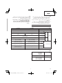
Table 3 Charging time (At 20°C)
(AC power supply / DC 12V (in-car) power supply)
Charger
Battery
UC18YML2
UC18YRSL
UC18YFSL
UC18YGSL
BSL1820
Approx.
30/80 min.
Approx.
30 min.
Approx.
60 min.
BSL1430
BSL1830
Approx.
45/120 min.
Approx.
45 min.
Approx.
90 min.
BSL1440
BSL1840
Approx.
60/160 min.
Approx.
60 min.
Approx.
120 min.
NOTE
The recharging time may vary according to the ambient
temperature and power source voltage.
<UC18YML2>
Especially, using a DC 12V in-car power
source may
require longer recharging time at high temperatures.
CAUTION
When the battery charger has been continuously used,
the battery charger will be heated, thus constituting
the cause of the failures. Once the charging has been
completed, give 15 minutes rest until the next charging.
4. Disconnect the charger’s power cord from the
receptacle or cigarette lighter socket
5. Hold the charger fi rmly and pull out the battery.
NOTE
Be sure to pull
out the battery from the charger after use,
and then keep it.
How to make the batteries perform longer
(1) Recharge the batteries before they become completely
exhausted.
When you feel that the power of the tool becomes
weaker, stop using the tool and recharge its battery. If
you continue to use the tool and exhaust the electric
current, the battery may be damaged and its life will
become
shorter.
(2) Avoid recharging at high temperatures.
A rechargeable battery will be hot immediately after use.
If such a battery is recharged immediately after use, its
internal chemical substance will deteriorate, and the
battery life will be shortened. Leave the battery and
recharge it after it has cooled for a while.
CAUTION
○ If the battery is charged while it is heated because it has
been left for a long time in a location subject to direct
sunlight or because the battery has just been used, the
pilot lamp of the charger lights up green. In such a case,
fi rst let the
battery cool, then start charging.
○ When the pilot lamp fl ickers in red (at 0.2-second
intervals), check for and take out any foreign objects in
the charger’s battery connector. If there are no foreign
objects, it is probable that the battery or charger is
malfunctioning. Take it to your authorized Service
Center.
○ Since the built-in micro computer takes about 3 seconds to
confi rm that the battery being charged with UC18YML2 /
UC18YRSL / UC18YFSL / UC18YGSL is taken out,
wait for a minimum of 3 seconds before reinserting it to
continue charging. If the battery is reinserted within 3
seconds,
the battery may not be properly charged.
○ Check the voltage of the in-car power source when
the pilot lamp fl ickers in green (every 0.2 seconds)
continuously. (UC18YML2)
If the voltage is 12V or lower, it indicates that the car
battery has weakened and cannot be charged.
○ If the pilot lamp does not blink in red (every second) even
though the charger cord or cigarette lighter connecting
plug is connected to the power, it indicates that the
protection circuit of the charger may be activated.
Remove the cord or plug from the power and then
connect it
again after 30 seconds or so. If this does
not cause the pilot lamp to blink in red (every second),
please take the charger to the Hitachi Authorized Service
Center.
PRIOR TO OPERATION
Setting up and checking the work environment
Check if the work environment is suitable by following the
precautions.
HOW TO USE
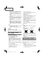
1. Confi rm the clutch dial position (See Fig. 5)
The three modes of screwdriver, drill and impact drill can
be switched by the position of the clutch dial in this unit.
(1) When using this unit as a screwdriver, line up the one of
the numbers “1, 3, 5 ... 22” on the clutch dial, or the dots,
with the triangle mark on the outer body.
(2) When using this unit as a drill, align the clutch dial drill
mark “
” with the triangle mark on the outer body.
(3) When using this unit as an impact drill, align the clutch
dial hammer mark “
” with the triangle mark on the outer
body.
CAUTION
○ The clutch dial cannot be set between the numerals “1, 3,
5 ... 22” or the dots.
○ Do not use with the clutch dial numeral between “22”
and the line at the middle of the drill mark. Doing so may
cause
damage (See Fig. 6).
2. Tightening torque adjustment
(1) Tightening torque
Tightening torque should correspond in its intensity to
the screw diameter. When too strong torque is used,
the screw head may be broken or be injured. Be sure
to adjust the clutch dial position according to the screw
diameter.
(2) Tightening torque indication
The
tightening torque diff ers depending on the type of
screw and the material being tightened.
The unit indicates the tightening torque with the numbers
“1, 3, 5 ... 22” on the clutch dial, and the dots. The
tightening torque at position “1” is the weakest and the
torque is strongest
at the highest number (See Fig. 5).
(3) Adjusting the tightening torque
Rotate the clutch dial and line up the numbers “1, 3, 5 ...
22” on the clutch dial, or the dots, with the triangle mark
on the outer body. Adjust the clutch dial in the weak or the
strong
torque direction according to the torque you need.
CAUTION
○ The motor rotation may be locked to cease while the unit
is used as drill. While operating the driver drill, take care
not to lock the motor.
○ Too long hammering may cause the screw broken due to
excessive tightening.
3. Rotation to Impact changeover (See Fig. 5)
The “Rotation (Rotation
only)” and “Impact (Impact +
Rotation)” can be switched by aligning the drill mark
“
” or the hammer mark “ ” with the triangle mark on
the outer body.
○ To make holes in the metal, wood or plastic, switch to
“Rotation (Rotation only)”.
○ To make holes in bricks or concrete blocks, switch to
“Impact (Impact + Rotation)”.

English
12
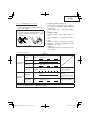
Table 4
Work Clutch dial position Suggestions
Drilling
Brick
Use for drilling purpose.
Wood
Steel
Aluminum
Driving
Machine screw 1 – 22 Use the bit or socket matching the screw diameter.
Wood screw
1 –
Use after drilling a pilot hole.
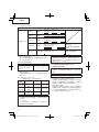
6. How to select tightening torque and rotational speed
Table 5
Use
Clutch Dial
Position
Rotating speed selection (Position of the shift knob)
LOW (Low speed) HIGH (High speed)
Driving
Machine screw 1 – 22
For 4 mm or smaller diameter
screws.
For 6 mm or smaller diameter
screws.
Wood screw
1 –
For 8 mm or smaller nominal
diameter screws.
For 3.8 mm or smaller nominal
diameter screws.
Drilling
Brick
For 13 mm or smaller diameters.
(DV14DBEL)
For 13 mm or smaller diameters.
(DV18DBEL)
For 10 mm or smaller diameters.
(DV14DBEL)
For 10 mm or smaller diameters.
(DV18DBEL)
Wood
For 36 mm or smaller diameters.
(DV14DBEL)
For 38 mm or smaller diameters.
(DV18DBEL)
For 18 mm or smaller diameters.
(DV14DBEL)
For 22 mm or smaller diameters.
(DV18DBEL)
Metal
For drilling with a metal working
drill bit.
––––––––––––
CAUTION
○ The selection examples shown in Table 5 should be
considered as general standard. As diff erent types of
tightening screws and diff erent materials to be tightened
are used in actual works proper adjustments are naturally
necessary.
○ When using the impact driver drill with a machine screw
at
HIGH (high speed), a screw may damage or a bit may
loose due to the tightening torque is too strong. Use the
driver drill at LOW (low speed) when using a machine
screw.
NOTE
○ The use of the battery in a cold condition (below 0 degree
Centigrade) can sometimes result in
the weakened
tightening torque and reduced amount of work. This,
however, is a temporary phenomenon, and returns to
normal when the battery warms up.
○ When using the unit as an impact drill, prolonged
operation of 5 minutes or more will result in internal heat
which may cause a repeated noise
other than the sound
normally emitted by the motor. This does not indicate a
malfunction.
Discontinuing use of the unit and allowing its internal
temperature to cool down will eliminate the noise.
For prolonged use, allow the unit to cool down
periodically.
7. Using the hook
The hook is used to hang up the power
tool to your waist
belt while working.
CAUTION
○ When using the hook, hang up the power tool fi rmly not to
drop accidentally.
If the power tool is dropped, it may lead to an accident.
CAUTION
If an operation which is normally performed at the
“Rotation” setting is performed at “Impact” setting,
the
eff ect of making holes does not only increase but it may
also damage the bit or other parts.
4. Change rotation speed
Operate the shift knob to change the rotational speed.
Move the shift knob in the direction of the arrow (See
Figs. 7 and 8).
When the shift knob is set to
“LOW”, the drill rotates at a
low speed. When set to “HIGH”, the drill rotates at a high
speed.
CAUTION
○ When changing the rotational speed with the shift knob,
confi rm that the switch is off .
Changing the speed while the motor is rotating will
damage the gears.
○ When
setting the shift knob to “HIGH” (high speed)
and the position of the clutch dial is “17” or “22”, it may
happen that the clutch is not engaged and that the motor
is locked. In such a case, please set the shift knob to
“LOW” (low speed).
○ If the motor
is locked, immediately turn the power off . If
the motor is locked for a while, the motor or battery may
be burnt.
Be sure to turn the shift knob.
5. The scope and suggestions for uses
The usable scope for various types of work based on the
mechanical structure of this unit is shown in Table 4
.

English
13
○ When carrying the power tool with hooked to your waist
belt, do not fi t any bit to the tip of power tool. If the sharp
bit such as drill is fi tted to the power tool when carrying it
with hooked to your waist belt, you will be injured.
○ Install
securely the hook. Unless the hook is securely
installed, it may cause an injury while using.
(1) Removing the hook.
Remove the screws fi xing the hook with Phillips screw
driver.(Fig. 9)
(2) Replacing the hook and tightening the screws.
Install securely the hook in the groove of power tool and
tighten the
screws to fi x the hook fi rmly. (Fig. 10)
8. Using the light
Pull the trigger switch to light up the light. The light keeps
on lighting while the trigger switch is being pulled. The
light goes out after releasing the trigger switch. (Fig. 11)
(The light automatically goes out 10 seconds after
releasing the
trigger switch.)
CAUTION
Do not expose directly your eye to the light by looking into
the light.
If your eye is continuously exposed to the light, your eye
will be hurt.
9. Mounting and dismounting of the bit
(1) Mounting the bit
Loosen the sleeve by turning it toward the left (in the
counterclockwise direction as viewed from the
front)
to open the clip on the keyless chuck. After inserting a
driver bit, etc., into the keyless drill chuck, and tighten
the sleeve by turning it toward the right (in the clockwise
direction as viewed from the front). (See Fig. 12)
○ If the sleeve becomes loose during operation, tighten it
further.
The tightening force becomes stronger when the sleeve
is tightened additionally.
(2) Dismounting the bit
Loosen the sleeve by turning it toward the left (in the
counterclockwise direction as viewed from the front), and
then take out the bit etc. (See Fig. 12)
NOTE
If the sleeve is tightened in a
state where the clip of the
keyless chuck is opened to a maximum limit, a click
noise may occur. This is the noise that occurs when the
loosening of the keyless chuck is prevented and is not a
malfunction.
CAUTION
When it is no longer possible to loosen the sleeve, use a
vise or similar instrument to secure the bit. Set the clutch
mode between 1 and 7 and then turn the sleeve to the
loose side (left side) while operating the clutch. It should
be easy now to loosen the sleeve.
10. Automatic spindle-lock mechanism
This unit has automatic spindle-lock mechanism for quick
bit changes.
11. Con
fi rm that the battery is mounted correctly
12. Check the rotational direction
The bit rotates clockwise (viewed from the rear side) by
pushing the R-side of the selector button.
The L-side of the selector button is pushed to turn the bit
counterclockwise. (See Fig. 13) (The
and marks
are provided on the body.)
CAUTION
Always use this unit with clockwise rotation, when using it
as an impact drill.
13. Switch operation
○ When the trigger switch is depressed, the tool rotates.
When the trigger is released, the tool stops.
○ The rotational speed of the drill can be controlled by
varying the amount that the trigger switch is pulled.
Speed is low when the trigger switch is pulled slightly and
increases as the trigger switch is pulled more.
NOTE
A buzzing noise is produced when the motor is about to
rotate;
This is only a noise, not a machine failure.
14. For drilling into brick
Excessive pressing force never increases drilling speed.
It will not only damage the drill tip or reduce working
effi ciency, but could also shorten the service life of
drill bit. Operate the impact driver drill within 10-15 kg
pressing force while
drilling into brick.
OPERATIONAL CAUTIONS
○ Resting the unit after continuous work
(1) The power tool is equipped with a temperature protection
circuit to protect the motor.
Continuous bolt-tightening work may cause the
temperature of the unit to rise, activating the temperature
protection circuit and automatically stopping operation.
If this happens, allow the power tool to cool before
resuming use.
(2) After
use for continuous tightening wood screw works,
rest the unit for 15 minutes or so when replacing the
battery. The temperature of the motor, switch, etc., will
rise if the work is started again immediately after battery
replacement, eventually resulting in burnout.
MAINTENANCE AND INSPECTION
1. Inspecting the tool
Since use of a dull tool will degrade effi ciency and cause
possible motor malfunction, sharpen or replace the tool
as soon as abrasion is noted.
2. Inspecting the mounting screws
Regularly inspect all mounting screws and ensure that
they are properly tightened. Should any of the screws be
loose, retighten them immediately. Failure
to do so could
result in serious hazard.
3. Maintenance of the motor
The motor unit winding is the very “heart” of the power
tool.
Exercise due care to ensure the winding does not
become damaged and/or wet with oil or water.
4. Cleaning on the outside
When the driver drill is stained, wipe with a soft dry cloth
or a
cloth moistened with soapy water. Do not use chloric
solvents, gasoline or paint thinner, for they melt plastics.
5. Storage
Store the driver drill in a place in which the temperature is
less than 40°C and out of reach of children.
NOTE
Make sure that the battery is fully charged when stored
for
a long period (3 months or more). The battery with
smaller capacity may not be able to be charged when
used, if stored for a long period.
NOTE
Storing Lithium-ion Batteries
Make sure the lithium-ion batteries have been fully
charged before storing them.
Prolonged storage of batteries with a low charge may
result in performance deterioration, signifi cantly reducing
battery usage time or rendering the batteries incapable of
holding a charge.
However, signifi cantly reduced battery usage time may
be recovered by repeatedly charging and using the
batteries two to fi ve times.

English
14
If the battery usage time is extremely short despite
repeated charging and use, consider the batteries dead
and purchase new batteries.
6. Service parts list
CAUTION
Repair, modifi cation and inspection of Hitachi Power
Tools must be carried out by a Hitachi Authorized Service
Center.
This Parts List will be helpful if presented with the
tool to
the Hitachi Authorized Service Center when requesting
repair or other maintenance.
In the operation and maintenance of power tools, the
safety regulations and standards prescribed in each
country must be observed.
MODIFICATIONS
Hitachi Power Tools are constantly being improved
and modifi ed to incorporate the latest technological
advancements.
Accordingly,
some parts may be changed without prior
notice.
Important notice on the batteries for the Hitachi
cordless power tools
Please always use one of our designated genuine
batteries. We cannot guarantee the safety and
performance of our cordless power tool when used with
batteries other than these designated by us, or when
the battery is disassembled and modifi ed (such as
disassembly and replacement of cells or other internal
parts).
NOTE
Due to HITACHI’s continuing program of research and
development, the specifi cations herein are subject to
change without prior notice.

15

16
○
○
○
○

17
○
○
○
○
○
○

18
1
2
3
4
5
○
○
○
○
○

19
○
○

20
ページが読み込まれています...
ページが読み込まれています...
ページが読み込まれています...
ページが読み込まれています...
ページが読み込まれています...
ページが読み込まれています...
ページが読み込まれています...
ページが読み込まれています...
ページが読み込まれています...
ページが読み込まれています...
ページが読み込まれています...
ページが読み込まれています...
ページが読み込まれています...
ページが読み込まれています...
ページが読み込まれています...
ページが読み込まれています...
ページが読み込まれています...
ページが読み込まれています...
ページが読み込まれています...
ページが読み込まれています...
ページが読み込まれています...
ページが読み込まれています...
ページが読み込まれています...
ページが読み込まれています...
ページが読み込まれています...
ページが読み込まれています...
ページが読み込まれています...
ページが読み込まれています...
ページが読み込まれています...
ページが読み込まれています...
ページが読み込まれています...
ページが読み込まれています...
ページが読み込まれています...
ページが読み込まれています...
ページが読み込まれています...
ページが読み込まれています...
ページが読み込まれています...
ページが読み込まれています...
ページが読み込まれています...
ページが読み込まれています...
ページが読み込まれています...
ページが読み込まれています...
ページが読み込まれています...
ページが読み込まれています...
-
 1
1
-
 2
2
-
 3
3
-
 4
4
-
 5
5
-
 6
6
-
 7
7
-
 8
8
-
 9
9
-
 10
10
-
 11
11
-
 12
12
-
 13
13
-
 14
14
-
 15
15
-
 16
16
-
 17
17
-
 18
18
-
 19
19
-
 20
20
-
 21
21
-
 22
22
-
 23
23
-
 24
24
-
 25
25
-
 26
26
-
 27
27
-
 28
28
-
 29
29
-
 30
30
-
 31
31
-
 32
32
-
 33
33
-
 34
34
-
 35
35
-
 36
36
-
 37
37
-
 38
38
-
 39
39
-
 40
40
-
 41
41
-
 42
42
-
 43
43
-
 44
44
-
 45
45
-
 46
46
-
 47
47
-
 48
48
-
 49
49
-
 50
50
-
 51
51
-
 52
52
-
 53
53
-
 54
54
-
 55
55
-
 56
56
-
 57
57
-
 58
58
-
 59
59
-
 60
60
-
 61
61
-
 62
62
-
 63
63
-
 64
64


関連論文
-
Hitachi WH 18DBEL Handing Instructions
-
Hitachi DV 14DBL Handling Instructions Manual
-
Hikoki DS7DF ユーザーマニュアル
-
-
Hitachi DV18DSFL Handling Instructions Manual
-
Hikoki WR 14DSDL ユーザーマニュアル
-
-
-
Hitachi P14DSL Handling Instructions Manual
-