
D28490, D28491
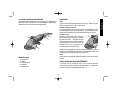
Heavy-Duty Angle Grinder
INSTRUCTION MANUAL

English 1
Simplified Chinese 10
Korea 21
Thai 30

English
1
SAVE THESE INSTRUCTIONS
WARNING! Read and understand all instructions. Failure to
follow all instructions listed below, may result in electric shock, fire
and/or serious personal injury.
General Safety Instructions
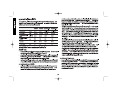
Technical data
WORK AREA
• Keep your work area clean and well lit. Cluttered benches
and dark areas invite accidents.
• Do not operate power tools in explosive atmospheres, such
as in the presence of flammable liquids, gases, or dust.
Power tools create sparks which may ignite the dust or fumes.
• Keep bystanders, children, and visitors away while operat-
ing a power tool. Distractions can cause you to lose control.
ELECTRICAL SAFETY
• Grounded tools must be plugged into an outlet properly in-
stalled and grounded in accordance with all codes and
ordinances. Never remove the grounding prong or modify
power supply system. Applicable only to Class II (double
insulated) tools.
• Avoid body contact with grounded surfaces such as pipes,
radiators, ranges and refrigerators. There is an increased risk
of electric shock if your body is grounded.
• Don’t expose power tools to rain or wet conditions. Water
entering a power tool will increase the risk of electric shock.
• Do not abuse the cord. Never use the cord to carry the tools
or pull the plug from an outlet. Keep cord away from heat, oil,
sharp edges or moving parts. Replace damaged cords immedi-
ately. Damaged cords increase the risk of electric shock.
PERSONAL SAFETY
• Stay alert, watch what you are doing and use common
sense when operating a power tool. Do not use tool while
tired or under the influence of drugs, alcohol, or medica-
tion. A moment of inattention while operating power tools may
result in serious personal injury.
D28490 D28491 D28490-B1 D28491-B1
Voltage Volt 220V 220V 220-240V 220-240V
Power input W 2000W 2000W 2000W 2000W
No-Load speed min
-1
6500 8500 6500 8500
Wheel diameter mm 230 180 230 180
Spindle M14 M14 M14 M14
Net weight kg 4.6 4.6 4.6 4.6
the plug in any way. Do not use any adapter plugs. Check
with a qualified electrician if you are in doubt as to whether
the outlet is properly grounded. If the tools should electrical-
ly malfunction or break down, grounding provides a low resist-
ance path to carry electricity away from the user. Applicable
only to Class I (grounded) tools.
• Double insulated tools are equipped with a polarized plug
(one blade is wider than the other.) This plug will fit in a
polarized outlet only one way. If the plug does not fit fully in
the outlet, reverse the plug. If it still does not fit, contact a
qualified electrician to install a polarized outlet. Do not
change the plug in any way. Double insulation eliminates the
need for the three wire grounded power cord and grounded

English
2
• Dress properly. Do not wear loose clothing or jewelry.
Contain long hair. Keep your hair, clothing, and gloves
away from moving parts. Loose clothes, jewelry, or long hair
can be caught in moving parts. Air vents often cover moving
parts and should also be avoided.
• Avoid accidental starting. Be sure switch is off before plug-
ging in. Carrying tools with your finger on the switch or plugging
in tools that have the switch on invites accidents.
• Remove adjusting keys or wrenches before turning the tool
on. A wrench or a key that is left attached to a rotating part of
the tool may result in personal injury.
• Do not overreach. Keep proper footing and balance at all
times. Proper footing and balance enables better control of the
tool in unexpected situations.
• Use safety equipment. Always wear eye protection. Dust
mask, non-skid safety shoes, hard hat, or hearing protection
must be used for appropriate conditions.
TOOL USE AND CARE
• Use clamps or other practical way to secure and support
the workpiece to a stable platform. Holding the work by hand
or against your body is unstable and may lead to loss of control.
• Do not force tool. Use the correct tool for your application.
The correct tool will do the job better and safer at the rate for
which it is designed.
• Do not use tool if switch does not turn it on or off. Any tool
that cannot be controlled with the switch is dangerous and must
be repaired.
• Disconnect the plug from the power source before making
any adjustments, changing accessories, or storing the tool.
Such preventative safety measures reduce the risk of starting
the tool accidentally.
• Store idle tools out of reach of children and other untrained
persons. Tools are dangerous in the hands of untrained users.
• Maintain tools with care. Keep cutting tools sharp and
clean. Properly maintained tools, with sharp cutting edges are
less likely to bind and are easier to control.
• Check for misalignment or binding of moving parts, break-
age of parts, and any other condition that may affect the
tools operation. If damaged, have the tool serviced before
using. Many accidents are caused by poorly maintained tools.
• Use only accessories that are recommended by the manu-
facturer for your model. Accessories that may be suitable for
one tool may become hazardous when used on another tool.
SERVICE
• Tool service must be performed only by qualified repair
personnel. Service or maintenance performed by unqualified
personnel could result in a risk of injury.
• When servicing a tool, use only identical replacement parts.
Follow instructions in the Maintenance section of this manual.
Use of unauthorized parts or failure to follow Maintenance
instructions may create a risk of electric shock or injury.
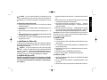
Additional Specific Safety Instructions
for Grinders
• Always use proper guard with grinding wheel. A guard pro-
tects operator from broken wheel fragments and wheel contact.
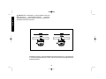
• Accessories must be rated for at least the speed recom-
mended on the tool warning label. Wheels and other acces-
sories running over rated speed can fly apart and cause injury.
Refer to the table below. Accessory ratings are above rated no-
load tool speeds because actual tool speeds may vary.
NOTE: The rated no load tool speed is printed on the name plate
and embossed on the gear case.

English
3
CAUTION: Use extra care when grinding into a corner because a
sudden, sharp movement of the grinder may be experienced when the
wheel contacts a secondary surface.
• Clean out your tool often, especially after heavy use. Dust
and grit containing metal particles often accumulate on interior
surfaces and could create an electric shock hazard.
CAUTION: Wear appropriate personal hearing protection dur-
ing use. Under some conditions and duration of use, noise from this
product may contribute to hearing loss.
WARNING: Some dust created by power sanding, sawing, grind-
ing, drilling, and other construction activities contains chemicals
known to cause cancer, birth defects, or other reproductive harm.
Some examples of these chemicals are:
• lead from lead-based paints,
• crystalline silica from bricks and cement and other masonry
products, and
• arsenic and chromium from chemically-treated lumber (CCA).
Your risk from these exposures varies, depending on how often you
do this type of work. To reduce your exposure to these chemicals:
work in a well ventilated area, and work with approved safety equip-
ment, such as those dust masks that are specially designed to fil-
ter out microscopic particles.
• Avoid prolonged contact with dust from power sanding,
sawing, grinding, drilling, and other construction activities.
Wear protective clothing and wash exposed areas with
soap and water. Allowing dust to get into your mouth, eyes, or
lay on the skin may promote absorption of harmful chemicals.
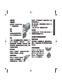
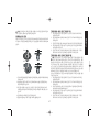
• The label on your tool may include the following symbols.
V ..........volts A..............amperes
Hz ........hertz W ............watts
min ......minutes ............alternating current
• Hold tool by insulated gripping surfaces when performing
an operation where the cutting tool may contact hidden
wiring or its own cord. Contact with a “live” wire will make
exposed metal parts of the tool “live” and shock the operator.
• Before using, inspect recommended accessory for cracks
or flaws. If such a crack or flaw is evident, discard the acces-
sory. The accessory should also be inspected whenever you
think the tool may have been dropped.
• When starting the tool with a new or replacement wheel, or
a new or replacement wire brush installed, hold the tool in
a well protected area and let it run for one minute. If the
wheel has an undetected crack or flaw, it should burst in less
than one minute. If the wire brush has loose wires, they will be
detected. Never start the tool with a person in line with the
wheel. This includes the operator.
• In operation, avoid bouncing the wheel or giving it rough
treatment. If this occurs, stop the tool and inspect the wheel.
• Direct sparks away from operator, bystanders or flammable
materials. Sparks may be produced while using a sander or
grinder. Sparks may cause burns or start fires.
• Always use side handle. Tighten the handle securely. The
side handle should always be used to maintain control of the tool
at all times.
....direct current
n
o ............no load speed
........Class II Construction …/min......revolutions or
........earthing terminal ................reciprocation per
........safety alert symbol ................minute

English
4
Features
SWITCH
The tool is controlled by a trigger switch (A). A lock-on button (B)
provides increased comfort in extended use applications.
MULTIPLE SIDE HANDLE POSITIONS
The side handle can be properly positioned in two locations based
on personal preference and application. The side handle must be
used at all times to maintain proper control of the tool.
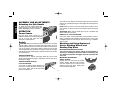
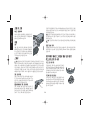
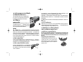
SPINDLE LOCK
The spindle lock pin is provided to pre-
vent the spindle from rotating when
installing or removing wheels. Operate
the spindle lock pin only when the tool is
turned off and unplugged from the power
source. To engage the lock, depress the
spindle lock button (C) and rotate the
spindle until you are unable to rotate it
further.
NOTE: Never depress the spindle lock button while the grinder is
running. Never turn on the grinder while the spindle lock button is
depressed. Damage to your tool may result.
MOUNT
The grinder is equipped with a mount, enabling easy wheel instal-
lation and removal.
Accessories and Attachments
It is important to choose the correct guards, backing pads
and flanges to use with grinder accessories. See the chart on
pages 5 for information on choosing the correct accessories.
C
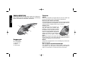
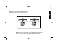
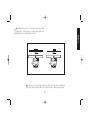
FAMILIARIZATION
Large Angle Grinders and Large Angle Sanders are designed for
heavy material removal in extended use applications. The following
grinders and sanders are described in this manual.
Components
A. Trigger Switch
B. Lock On Button
C. Spindle Lock
D. Guard
E. Side Handle
A
B
D
E
C

English
5
CAUTION: Accessories must be rated for at least the speed
recommended on the tool warning label. Wheels and other acces-
sories running over rated speed can fly apart and cause injury.
NOTE: Wheel size must match guard size; i.e., a new 180mm wheel may not be used with a
230mm guard. The bottom surface of wheel must be inside the bend of the guard lip.

English
6
To turn the tool off, depress and release trigger. The lock pin button
will pop out, permitting the trigger to disengage and causing the tool
to turn off.
NOTE: Allow the tool to reach full speed before touching tool to
work surface. Lift the tool from the work surface before turning the
tool off.
CAUTION: Make sure the wheel has come to a complete stop
before setting the tool down.
REMOVAL OF LOCK-ON FEATURE
The lock-on button can be permanently removed without compro-
mising compliance with regulatory agencies shown on the tool’s
nameplate. Removal of the lock pin must be done by a DEWALT
service center.
Mounting and Using Depressed
Center Grinding Wheels and
Sanding Flap Discs
MOUNTING AND REMOVING GUARD
Turn off and unplug tool before making any adjustments or
removing or installing accessories. Before reconnecting the
tool, depress and release the trigger switch to ensure that the
tool is off.
IMPORTANT INFORMATION
ABOUT GUARDS
Guards must be used with all grinding
wheels, sanding flap discs, wire brushes
and wire wheels. The tool may be used
without a guard only when sanding with
conventional sanding discs.
ASSEMBLY AND ADJUSTMENTS
Attaching the Side Handle
To install the side handle, thread the
handle into one of the two positions and
tighten securely by turning clockwise.
OPERATION
Power Source
Plug the large angle grinder into a
dedicated electrical circuit. Operating this
tool on a circuit with other tools will
decrease tool performance.
Switch
CAUTION: Before connecting the tool to a power source or after
a power failure, depress and release the trigger switch (A) once
without depressing the lock-on button (B) to ensure that the switch
is in the off position. If the trigger switch is locked on, the tool will
start unexpectedly when power is reconnected to the tool. Hold the
side handle and rear handle firmly to maintain control of tool at start
up and during use.
TRIGGER OPERATION
To turn the tool on, depress the trigger switch (A). The tool will
remain running while the trigger is depressed. Turn the tool off by
releasing the trigger.
TRIGGER OPERATION WITH
LOCK-ON FEATURE
To turn tool on, depress trigger. Depress and
hold lock-on button (B) while releasing trig-
ger. Lock-on button will remain depressed
and tool will remain on.
A
B

English
7
CAUTION: When using a grinding wheel with a guard, be sure
that the bottom surface of the grinding wheel is inside the the
guard lip.
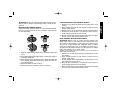
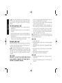
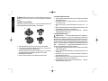
MOUNTING NON-HUBBED WHEELS
Depressed center, grinding wheels must be used with available
accessory flanges. See the charts on pages 5 of this manual
for more information.
1. Install the metal backing flange (G) on spindle (E) against the
mount.
G
E
H
2. Place wheel against the backing flange, centering the wheel on
the backing flange pilot.
3. While depressing the spindle lock button, thread the clamp nut
(H) on spindle, piloting the raised hub on clamp nut in the cen-
ter of grinding wheel.
4. Tighten the clamp nut with a wrench.
5. Reverse the above procedure to remove the wheel.
SURFACE GRINDING WITH GRINDING WHEELS
1. Allow the tool to reach full speed before touching tool to work
surface.
2. Apply minimum pressure to work surface, to allow the tool to
operate at high speed.
3. Maintain a 20˚ to 30˚ angle between the tool and work surface.
4. Continuously move the tool in a forward and back motion to
avoid creating gouges in the work surface.
5. Remove the tool from work surface before turning tool off. Allow
the tool to stop rotating before setting it down.
EDGE GRINDING WITH GRINDING WHEELS
CAUTION: Wheels used for cutting and edge grinding may
break if they bend or twist while the tool is being used to do
cut-off work or deep grinding. To reduce the risk of serious injury,
limit the use of these wheels with a standard guard to shallow
cutting and notching (less than 1/2" in depth). The open side of
the guard must be positioned away from the operator. For deeper
cutting with a wheel, use a closed, guard.
Guards are available at extra cost from your local dealer or
authorized service center.
1. Allow the tool to reach full speed before touching the tool to the
work surface.
2. Apply minimum pressure to work surface, to allow the tool to
operate at high speed.
3. Protect yourself during edge finishing by directing the open
side of the guard away from you.
4. Move the tool continuously in a forward and back motion to
avoid creating gouges in the work surface.
5. Remove tool from work surface before turning the tool off. Allow
the tool to stop rotating before setting it down.

English
8
WARNING: Do not use edge grinding wheels for surface grind-
ing applications because edge grinding wheels are not designed
for side pressures encountered with surface grinding. Wheel break-
age and injury may result.
SURFACE FINISHING WITH SANDING FLAP DISCS
1. Allow the tool to reach full speed before touching tool to work
surface.
2. Apply minimum pressure to work surface, to allow the tool to
operate at high speed.
3. Maintain a 5˚ to 10˚ angle between the tool and work surface.
4. Continuously move the tool in a forward and back motion to
avoid creating gouges in the work surface.
5. Remove the tool from work surface before turning tool off. Allow
the tool to stop rotating before setting it down.
Mounting and Using Cutting Wheels
Cutting wheels include diamond wheels and abrasive discs.
Abrasive cutting wheels for metal and concrete use are available.
Diamond blades for concrete cutting can also be used.
WARNING: A closed, cutting wheel guard is not included with
this tool. Cutting wheels require proper flanges and guards. A
180mm cutting guard, is available as an accessory and includes
proper, matching flanges. Failure to use proper flange and
guard can result in injury resulting from wheel breakage and
wheel contact.
MOUNTING CLOSED GUARD
Turn off and unplug tool before making any adjustments or
removing or installing accessories. Before reconnecting the
tool, depress and release the trigger switch to ensure that the
tool is off.
1. Align the lugs with slots on the gear case cover. Position the
guard facing backward, as shown.
2. Push the guard down until the guard lug engages and rotates
freely in the groove on the gear case hub.
3. Rotate guard into desired working position. The guard body
should be positioned between the spindle and the operator to
provide maximum operator protection.
4. Secure the guard on the gear case cover. You should be
unable to rotate the guard by hand when the latch is in closed
position. Do not operate grinder with a loose guard or clamp
lever in open position.
NOTE: The guard is pre-adjusted to the diameter of the gear case
hub at the factory. If, after a period of time, the guard becomes
loose, tighten the adjusting screw.
MOUNTING CUTTING WHEELS
1. Remove mount.
2. Install wheel backing flange, aligning flats on spindle with flats
on backing flange.
3. Place the wheel on the backing flange, centering the wheel on
the backing flange pilot.
4. Install the clamp nut, ensuring that the wheel remains centered
on the backing flange.
5. Depress the spindle lock button and tighten clamp nut with wrench.
6. Reverse the above procedure to remove the wheel.
USING CUTTING WHEELS
1. Allow tool to reach full speed before touching tool to work sur-
face.
2. Apply minimum pressure to work surface, allowing tool to oper-
ate at high speed.
3. Once you begin a cut, maintain the angle of the cutting wheel

English
9
to the work surface. This will keep you from bending the wheel
which could result in wheel breakage and injury.
4. Remove the tool from work surface before turning tool off. Allow
the tool to stop rotating before setting it down.
MAINTENANCE
Cleaning
Blowing dust and grit out of the motor housing using clean, dry
compressed air is a necessary regular maintenance procedure.
Dust and grit containing metal particles often accumulate on interi-
or surfaces and could create an electrical shock hazard if not fre-
quently cleaned out. ALWAYS WEAR SAFETY GLASSES.
CAUTION: Never use solvents or other harsh chemicals for
cleaning the non-metallic parts of the tool. Use a clean, dry rag
only.
Lubrication
DEWALT tools are properly lubricated at the factory and are ready
for use.
Repairs
To assure product SAFETY and RELIABILITY, repairs, mainte-
nance and adjustment should be performed by authorized service
centers or other qualified service personnel. Always use identical
replacement parts.
Motor Brushes
When brushes become worn, the tool will automatically stop, pre-
venting damage to the motor. Brush replacement should be per-
formed by DEWALT authorized service centers or other qualified
service personnel. Qualified service personnel should follow the
procedures below when replacing motor brushes.
Turn off and unplug tool before making any adjustments or
removing or installing accessories. Before reconnecting the
tool, depress and release the trigger switch to ensure that the
tool is off.
1. Remove the brush doors located on the sides of motor hous-
ing.
2. To remove the brush, hold the female terminal, which is
attached to the brush lead wire, and disconnect the female ter-
minal from the male terminal.
3. Pull the brush straight up out of the brush holder.
4. Replace brushes, in pairs, with original D
EWALT brushes avail-
able from DEWALT authorized service centers.
5. Ensure that the brushes slide freely in brush box.
6. Reconnect the brush lead wire to brush box terminal.
7. Re-install the brush doors before using the tool. Torque screws
to 10 in-lbs, maximum. Overtightening may cause screws to
strip.
Purchasing Accessories
Recommended accessories for use with your tool are available at
extra cost from you local dealer or authorized service center.
CAUTION: The use of any other accessory not recommended
for use with this tool could be hazardous.

Simplified Chinese
10
一般安全规定
D28490 D28491 D28490-B1 D28491-B1
电压 伏特
220V 220V 220-240V 220-240V
输入功率 瓦
2000W 2000W 2000W 2000W
空载速度 分钟
6500 8500 6500 8500
砂轮直径 毫米
230 180 230 180
主轴
M14 M14 M14 M14
净重 千克
4.6 4.6 4.6 4.6
a)工作场地
1)保持工作场地清洁和明亮。混乱和黑暗的场地会引发事故。
2)不要在易爆环境,如有易燃液体、气体或粉尘的环境下操作电
动工具。电动工具产生的火花会点燃粉尘或气体。
3)让儿童和旁观者离开后操纵电动工具。分心会使你放松控制。
b)电气安全
1)电动工具插头必须与插座相配。不能以任何方式改装插头。需
接地的电动工具不能使用任何转换插头。未经改装的插头和相配
的插座将减少触电危险。
2)避免人体接触接地表面,如管道、散热片和冰箱。如果你身体
接地会增加触电危险。
3)不得将电动工具暴露在雨中或潮湿环境中。水进入电动工具将
增加触电危险。
4)不得滥用电线。绝不能用电线搬运、拉动电动工具或拔出其插
头。让电动工具远离热、油、锐边或运动部件。受损或缠绕的电
线会增加触电危险。
5)当在户外使用电动工具时,使用适合户外使用的外接电线。适
合户外使用的电线将减少触电危险。
c)人身安全
1)保持警觉,当操作电动工具时关注所从事的操作并保持清醒。
切勿在有疲倦、药物、酒精或治疗反应下操作电动工具。在操作
电动工具期间精力分散会导致严重人身伤害。
2)使用安全装置。始终配载护目镜。安全装置,诸如适当条件下
的防尘面具、防滑安全鞋、安全帽、听力防护等装置能减少人身
伤害。
3)避免突然起动。确保开关在插入插头时处于关断位置。手指放在
已接通电源的开关上或开关处于接通时插入头可能会导致危险。
4)在电动工具接通之前,拿掉所有调节钥匙或扳手。遗留在电动
工具旋转零件上的扳手或钥匙会导致人身伤害。
5)手不要伸得太长。时刻注意脚下和身体平衡。这样在意外情况
下能很好地控制电动工具。
6)着装适当。不要穿宽松衣服或佩带饰品。让你的头发、衣服和袖
子远离运动部件。宽松衣服、佩饰或长发可能会卷入运动部件。
7)如果提供了与排屑装置、集尘设备连接用的装置,则确保他们
连接完好且使用得当。使用这些装置可减少碎屑引起的危险。
d)电动工具使用和注意事项
角向磨光机
D28490型/D28491型
欢迎购买得伟(DEWALT)产品!
技术参数

Simplified Chinese
11

Simplified Chinese
12

Simplified Chinese
13
•
•

Simplified Chinese
14
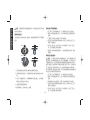
V ..........
电压
A..............
安培
Hz ........
赫兹
W ............
瓦特
min ......
分钟
............
交流电
....
直流电
n
o ............
空载速度
........
双重绝缘
…/min......
每分钟转数或
........
接地终端
................
往复次数
........
安全小心标志
................
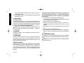
• 切割工具可能会接触到隐线或其自身的电缆线,因此在进行作
业时,必须握住工具的绝缘夹持面。工具如果与带电电线接触
会使工具的外露金属部件带电,从而使操作人员触电。
• 每次使用前应检查推荐的附件是否有裂纹或瑕疵。如果有明显
的裂纹或瑕疵,丢弃该附件。如果你认为工具可能跌落过,也
必须检查附件。
• 如果工具砂轮是新的、刚替换的,或者刚安上新的、替换的钢
丝刷,请在一个有周密保护的空间握住工具,让其运转一分钟
以上。如果砂轮有难以察觉的裂缝或瑕疵,那么该砂轮会在一
分钟内爆裂。如果钢丝刷有松脱的钢丝,就会被发现。严禁在
有人(包括操作人员本人在内)与砂轮之间成一直线时启动工
具。
• 请勿猛撞砂轮或者粗暴使用砂轮。如果出现这种情况,请关闭
工具进行检查。
• 防止火星碰到操作人员、旁观者或易燃物品。工具在切割或研
磨时,可能会产生火星。这些火星可能会导致(人员)烫伤或引
发火灾。
• 请一直使用并且紧握侧手柄。无论什么时候,都必须一直使用
侧手柄来保持对工具的控制。
注意:打磨边角时应格外当心,因为在砂轮接触第二平面时,
砂轮机会突然急剧地移动。
• 请经常清洁您的工具,尤其是在经过繁重使用后。含有金属微
粒的粉尘经常会沉积在工具的内表面,从而产生电击风险。
注意:在使用工具时,请佩带恰当的个人听力保护装置。在某
些情况下以及长期使用本产品时,本产品所产生的噪音可能会影
响听力。
警告:由电动打磨、切割、研磨、钻孔和其它一些建筑活动所
产生的某些灰尘包含一些致癌、导致不育或其他生殖性疾病的化
学物质。此类化学物质中的一些例子有:
• 铅基油漆中的铅
• 砖石、水泥和其它砖石结构产品中所含的石英
• 经过化学品处理的木材 (CCA) 中所含有的砷和铬
您接触这些物质的风险取决于您从事此类工作的频率。为了降低
接触这些化学物质的风险:保持工作场所通风良好、采用认可的
安全防护装备,例如过滤细微颗粒的专用防尘面具。
• 避免与电动打磨、切割、研磨、钻孔和其它一些建筑活动所产
生的灰尘有过长的接触。穿戴防护服并且用水和肥皂清洗外露
表面。如让灰尘进入您的口、眼或停留在皮肤上可能会促进对
有害化学物品的吸收。
• 您工具上的铭牌可能会包含如下符号。

Simplified Chinese
15
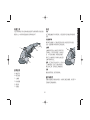
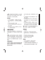
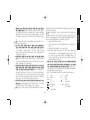
特点
配件与附件
C
熟悉工具
部件名称
A
B
F
D
E
C
大型角向砂轮机和大型角向磨光机适用于金属切削等扩展应用的
重型作业。本说明书描述的磨光机和砂轮机如下:
A. 触发开关
B. 锁定按钮
C. 主轴锁
D. 防护装置
E. 侧手柄
F. 电源线
开关
此工具通过触发开关(A)来控制。锁定按钮(B)在扩展应用时增加舒
适性。
多位置侧手柄
侧手柄可以根据个人习惯以及实际应用适当地安装在两个位置。
必须一直使用侧手柄来保持对工具的控制。
主轴锁
主轴锁销用于防止主轴在安装和卸下轮
子时转动。只有当关闭电源,拔掉插头
后,才可启动主轴锁。如欲啮合主轴锁,
请按下主轴锁按钮(C)并转动主轴直到
主轴不能转动为止。
说明:在工具处于作业状态时,切勿按
下主轴锁按钮;在按下主轴锁按钮时,
禁止启动工具,否则会给工具造成损伤。
托板
磨光机配有托板,便于装卸砂轮。
为磨光机选择正确的防护装置、衬垫和凸缘至关重要。参见第14
页表格来正确选择配件。

Simplified Chinese
16
.
说明:砂轮尺寸必须匹配防护装置的尺寸;即,230mm新砂轮不可以使用9″防护装置。
砂轮底面必须位于弯曲的防护凸缘内部。
注意:附件的额定速度必须至少达到工具警示牌的推荐速度。
如果砂轮和其它附件的旋转速度超过额定速度,可能会分离飞出,
造成伤害。

(A)
(B) OFF
(
)
(A)
(B)
Simplified Chinese
17
A
B

Simplified Chinese
18
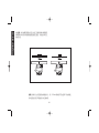
G
E
H
,
用砂轮进行平面磨削操作
1. 在工具与工件表面接触之前,必须确保本工具以全速运转。
2. 请向工件表面施加最小压力,这样可确保电动工具能够高速
运转。
3. 工具和工件表面之间保持20˚至30˚的角度。
4. 以前后运动方向持续不断的移动本工具,这样可防止在工件
表面产生凿槽(孔)。
5. 在关闭工具之前,先将工具从工件表面移开。在放下工具之
前,必须先确保工具停止旋转。
6. 建议用户采用得伟原装砂轮片;并选用标称最大转速1.1倍的
砂轮片。
用砂轮进行磨边操作
注意:在工具进行切割作业或深磨作业时,用于切割或磨边作
业的砂轮,如果被弯曲或扭曲,那么可能会爆裂。为了降低出现
严重伤害的风险,必须用标准的防护装置来限制此类砂轮的使用,
使其只能进行浅度切割和开槽作业(深度不到0.5英寸)。防护装置
开口面的定位不能对着操作人员。如欲用切割轮进行深度切割,
那么请使用密闭型的防护装置。您可从本地经销商处或特约维修
中心处另外付费购买到防护装置。
1. 在工具与工件表面接触之前,必须确保工具以全速运转。
2. 请向工件表面施加最小压力,这样可确保电动工具能够高速
运转。
3. 请注意磨边时的自我保护,不要让防护装置的开口对着您。
4. 以前后运动方向持续不断的移动本工具,这样可防止在工件
表面产生凿槽(孔)。
5. 在关闭工具之前,先将工具从工件表面移开。在放下工具之
前,必须先确保工具停止旋转。
注意:在使用配有防护装置的砂轮时,砂轮底面必须位于弯曲
的防护凸缘内部。
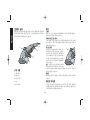
无毂砂轮的安装
凹心砂轮必须与配件凸缘一起使用。参阅本说明书第5页了解更多
信息。
1. 安装金属衬垫凸缘(G)到主轴(E)并支撑到安装垫上。
2. 将砂轮对准衬垫凸缘,并且使砂轮与衬垫凸缘导向的中心对
准。
3. 在按下主轴锁的同时,把锁紧螺母(H)拧到主轴上。引导锁紧
螺母上的凸毂进入砂轮中心。
4. 使用扳手紧固锁紧螺母。
5. 要拆除砂轮,反向操作以上步骤。
ページが読み込まれています...
ページが読み込まれています...
ページが読み込まれています...
ページが読み込まれています...
ページが読み込まれています...
ページが読み込まれています...
ページが読み込まれています...
ページが読み込まれています...
ページが読み込まれています...
ページが読み込まれています...
ページが読み込まれています...
ページが読み込まれています...
ページが読み込まれています...
ページが読み込まれています...
ページが読み込まれています...
ページが読み込まれています...
ページが読み込まれています...
ページが読み込まれています...
ページが読み込まれています...
ページが読み込まれています...
-
 1
1
-
 2
2
-
 3
3
-
 4
4
-
 5
5
-
 6
6
-
 7
7
-
 8
8
-
 9
9
-
 10
10
-
 11
11
-
 12
12
-
 13
13
-
 14
14
-
 15
15
-
 16
16
-
 17
17
-
 18
18
-
 19
19
-
 20
20
-
 21
21
-
 22
22
-
 23
23
-
 24
24
-
 25
25
-
 26
26
-
 27
27
-
 28
28
-
 29
29
-
 30
30
-
 31
31
-
 32
32
-
 33
33
-
 34
34
-
 35
35
-
 36
36
-
 37
37
-
 38
38
-
 39
39
-
 40
40


