
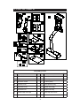
T672 Treadmill External Mount TV Bracket
Installation Instructions
L
R

T672 TV BRACKET ASSEMBLY - CONTENTS
1. SELECT A SUITABLE TV .................................................................. 2
2. INSPECT CORD SPECIFICATIONS ................................................ 3
3. LIST OF PARTS ................................................................................. 4
4. ASSEMBLE THE PRODUCT ............................................................. 6
STEP 1 Install the Gas Spring ............................................................... 7
STEP 2 Remove Motor Covers .............................................................. 8
STEP 3 Thread Cables through the Pedestal ........................................ 9
STEP 4 Install the TV Bracket and Cables ............................................ 10
STEP 5 Install the TV Screen ................................................................ 13
STEP 6 Install Covers onto the Bracket ................................................ 14
STEP 7 Install the Control Rod and Secure Cables ............................... 15
STEP 8 Install the Adapter ..................................................................... 15
STEP 9 Install the Power Cord .............................................................. 17
STEP 10 Install the Motor Covers .......................................................... 18
STEP 11 Adjust the TV Angle ................................................................. 19

2
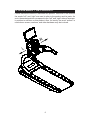
1. SELECT A SUITABLE TV
Although the SportsArt External Mount TV Bracket is designed to accommodate
most at screen TVs, not every at screen TV is suitable for use with this bracket.
Complicating the situation is the rapid development of new varieties of at screen
TVs. The following is a general guide for the purchase of at screen TVs that will
work with the external mount TV bracket. Please note that this guide is no substitute
for actual installation of a at screen TV, which is the best test of compatibility with
the TV bracket.
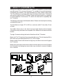
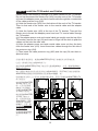
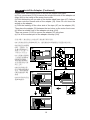
The following notes refer to the illlustration below. Please note these tips for selecting
a suitable at screen TV
Top left: Maximum height: 275 to 395 mm; maximum width 70 mm (at), 60 mm
(curved)
Top middle: Screen keys in the lower front area might interfere with the bracket.
Connectors facing downward are acceptable if the cables will not interfere with the
bracket.
Top right: Connectors facing the back will interfere with the TV bracket.
Bottom left: The TV bracket will accommodate at screen TVs with standard M3 or
M4 screw sizes and holes placed from 75 to 100 mm apart.
Bottom middle: Screw holes that are too high may not allow for a secure t against
the TV bracket.
Bottom left: A protrusion around screw holes would not allow for a secure t against
the TV bracket. And having low screw holes may not allow for a secure t against
the TV bracket.

3
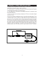
2. INSPECT CORD SPECIFICATIONS
In addition to the conguration of the at screen TV, other factors, including cord
specications and power supply, must be considered:
● The at screen TV must use a DC power cord. Never thread an AC power
cord through the pedestal of a tness product.
● The length of the cord between the adapter and the TV connector must
be at least 2500 mm.
● The core of this cord must have a diameter of 20 mm or less and a length
of 28 mm or less.
Core size can present installation issues. Cores that are smaller than 17 mm
in diameter and 23 mm in length can easily pass through the installation hole
and neck of the TV bracket. Cores that are larger than that but not larger
than 20 mm in diameter and 28 mm in length can still be installed. However,
you must first remove the cable protector ring from the TV bracket. Insert
the power cord and coaxial cable through the cable protector ring. Then
thread the cables through the TV bracket. After the cables have been in-
stalled properly, insert the cable protector ring into place on the TV bracket.

4
Assembly Parts
No. Name Qty. No. Name Qty.
A1 TV bracket 1 A9 Owner’s manual 1
A2 Right corner cover 2 A10 Cable clip 5
A3 Left corner corner 2 A11 Tie wire (short) 1
A4 Left back cover 1 A12 Cable protector ring 2
A5 Right back cover 1 A13 Feeder wire (long) 1
A6 Adjustment rod 1 A14 Adapter set strap 1
A7 Double-sided foam tape 1 A15 Cable clip with screws 1
A8 Hardware kit 1
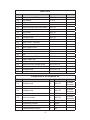
3. LIST OF PARTS

5
Other Parts
No. Name Specication Notes
31
Mushroom top Phillips screw M5*L12
32 Flat washer 15*5*t1
33
Adapter
34 Soft cap
35 Mushroom top inner hex screw M5*L12
36 Cable protector
37
Hex screw M5*L10
38 Phillips screw M5*L8
39
Phillips screw M4*L10
40 Flat washer 12*4.2*t1
41 Motor cover - left side
42 Motor cover - right side
43 Motor upper cover
44 Motor front cover
45 N/A
46 N/A
47 Mushroom top Phillips screw M5*L10
48 Plastic cable clip
49 Phillips screw M5*P0.8*L20
50 Mushroom top Phillips screw M5*P0.8*L12
51
N/A
52 Phillips screw M5*P0.8*L10
53 Coaxial cable
Components in the Hardware Kit
No. Name Qty. Specication Notes
21
Phillips screw 4 M3*L10
To secure
the screen
Flat washer 4 8*4*t1
22 Phillips screw 4 M4*L10
To secure
the screen
Flat washer 4 8*4*t1
23 Inner hex screw 4 M6*L65
To secure
the bracket
Screwdriver shank 1 Phillips/at
Screwdriver handle 1 green
T-shaped Allen wrench 2 M4
L-shaped Allen wrench 1 M6

6
4. ASSEMBLE THE PRODUCT
Follow instructions below to assemble this product. Note that in this manual
the words “left” and “right” are used to refer to the product and its parts. As
such, these designations correspond to the “left” and “right” sides of a person
in position to exercise on this product. Also, for brevity, the word “screws” is
used where screws, washers, and other hardware may be involved.
L
R

7
(b)
(a)
STEP 1 Install the Gas Spring
Before installing the TV bracket onto the product, first install the gas spring
onto the TV bracket.
(a) First, remove one screw to detach the set pin from the TV bracket (A1).
(b) Align the hole in the gas spring with the hole in its mount bracket. Make
sure that bushings are in place on the set pin. Insert the set pin and secure
it with the screws.
請先依下列步驟(a~b)組裝電視架的氣壓棒:
(a) 先將電視架組(A1)上的軸心及螺絲取下。
(b) 將氣壓棒對準孔位後將軸心與螺絲鎖回。(注意:鎖上氣壓棒前,請確認兩側需
有裝有塑膠襯套)

8
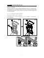
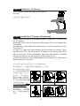
STEP 2 Remove Motor Covers
Turn off unit power before beginning this procedure, and follow instructions
in sequence.
(a) Loosen two screws (49). Then remove motor left (41) and right (42) side
covers.
(b) After loosening screws (50), remove the motor upper cover (43).
(c) Loosen screws (52), and remove the motor upper cover (44).
組裝步驟二 拆除馬達蓋
請依照順序拆解 (注意:拆解前,要先停機,關閉電源):
(a) 先鬆脫兩側螺絲(49),再將左右馬達蓋側板(41)(42)取下。
(b) 再鬆脫螺絲(50),將馬達上蓋(43)取下。
(c) 鬆脫螺絲(52),將馬達蓋前板(44)取下。
c
b
a
a

9
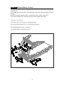
STEP 3 Thread Cables through the Pedestal
The illustration (right) shows
an overview of this step.
組裝步驟三 電源線ADAPTER和
TV端子線左支桿的穿線說明
L
R
(b)(a)
(c)
(e)
(d)
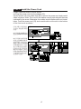
STEP 3 Thread Cables through the Pedestal (Continued)
Please follow instructions (a through i) to install cables into the pedestal.
(a) First, remove the cap (34) in the upper part of the left pedestal. This will
expose a hole in the pedestal.
(b) Insert the coaxial cable into the hole in the upper part of the pedestal. Do
not let the top part of the coaxial cable fall into the hole.
(c) Pull the bottom of the coaxial cable out from the square hole in the ped-
estal mount area.
(d) At the bottom of the pedestal, use the short wire tie (A11) to secure the
adapter power cord onto the coaxial cable.
(e) From the top of the pedestal, pull the coaxial cable to feed the adapter
power cord through the ped-
estal.
組裝步驟三 電源線ADAPTER和
TV端子線左支桿的穿線說明
請依下列步驟(a~i)組裝:
(a) 請先將左支桿上的管塞(34)
拆下。
(b) 將TV端子線由管塞(34)拆下
的孔穿入。
(c) 至總機台之內面方形孔穿
出。
(d) 再用短的扎線帶(A11)將電源
線ADAPTER和TV端子線先重疊
纏繞。
(e) 用手將TV端子線往上拉。

10
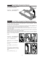
STEP 3 Thread Cables through the Pedestal (Continued)
(f) Pull the adapter cord out from the upper hole. Then disconnect the wire
tie (A11). Do not let the adapter cord fall into the hole.
(g) Insert the coaxial cable back into the hole in the pedestal. Do not let the
top of the coaxial cable fall into the hole.
(h) Then pull the bottom of the coaxial
cable out from the square hole in the
pedestal mount area.
(i) At the upper area of the pedestal,
insert the coaxial cable and adapter
power cord through the flat side of the
cable protector ring (A12). Insert the
cable protector ring back into the hole.
組裝步驟三 電源線ADAPTER和TV端子
線左支桿的穿線說明
(f) 將TV端子拉出後,將短的扎線帶(A11)
解開。
(g) 再將TV端子線穿入左支桿的孔內。
(h) 再將TV端子線由總機台前側內面的方
形孔拉出。
(i) 再將TV端子線與電源線ADAPTER穿
入護線環(A12),並將護線環套(A12)壓入
孔內
(注意:護線環(A12)的方向由不是圓弧的
方向先穿入) 。
(f)
(h)
(g)
(i)
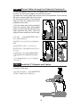
STEP 4 Install the TV Bracket and Cables
The illustration to the right provides an
overview of this step.
組裝步驟四 電視架組、電源線ADAPTER
和TV端子線電視架支桿穿線組裝

11
STEP 4 Install the TV Bracket and Cables (Continued)
Please follow instructions (a)
through (c) to install the TV
bracket onto the back of the
display.
(a) First, remove screws (35)
from the display lower cover.
(b) Remove the soft cap (34)
and cable protector ring (36).
(c) Align the base of the TV
bracket with the screw holes in
the display back. Use screws
(23) to secure the base of the
TV bracket onto the back of
the display.
組裝步驟四 電視架組、電源線
ADAPTER和TV端子線電視架支
桿穿線組裝
請依下列步驟(a~i)組裝:
(a) 先將儀表板下蓋的螺絲(35)取
下。
(b) 將管塞(34)和護線環(36)取
下。
(c) 將電視架套管(A1)插入儀表下
蓋孔內,再用螺絲(23)鎖緊。
(a)
(b)
(c)

12
(e)
(d)
(f)
(g)
(h)
(i)
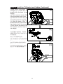
STEP 4 Install the TV Bracket and Cables
Please follow instructions (d) through (i) to install cables into the TV bracket.
Do not first disconnect the feeder wire (A13) from the neck of the TV bracket.
(d) Insert the adapter power cord and coaxial cable through the rounded side
of the cable protector ring (A36).
(e) Untie the feeder wire (A13) from the bottom of the neck of the TV bracket.
Then tie that end of the feeder wire to the coaxial cable and the adapter
cable.
(f) Untie the feeder wire (A13) at the top of the TV bracket. Then pull the
feeder wire to thread the adapter power cord and TV coaxial cable through
the TV bracket.
(g) If the adapter power cord and coaxial cable get caught near the top of the
TV bracket, remove the cap (34) and insert a finger into the hole to push the
cables out the hole the other side.
(h) After the adapter power cord and coaxial cable come out from the hole,
untie the feeder wire (A13). Insert these two cables through the flat side of
the protector ring (A36).
(i) Then insert the cable protector ring (A36) and the cap (34) into their re-
spective holes.
組裝步驟四 電視架組、電源線ADAPTER和TV端子線電視架支桿穿線組裝
(注意:請勿將長的扎線帶(A13)取下) 。
(d) 將電源線ADAPTER和TV端子線先穿入護線環(A36)內。注意:護線環(A36)由
圓弧方向先穿入。
(e) 先將附於電視架支桿內底部長的扎線帶(A13)解開。再將TV端子線放在電源線
ADAPTER的插頭底部再用解開的長扎線帶(A13)纏繞一起。
(f) 將電視架支桿內上方長的扎線帶(A13)也解開。再用手將電源線ADAPTER和TV
端子線拉出。
(g) 電源線ADAPTER
和TV端子線若卡住
時,可用手從管塞
(34)取下的孔輔助,
將電源線ADAPTER
和 TV端子線頂出。
(h).電源線ADAPTER
和TV端子線拉出
後,先將長的扎線
帶(A13)解開,再將
兩條線穿入護線環
(A36)內。注意:護
線環(A36)由不是圓
弧方向先穿入。
(i) 最後將管塞(34)和
護線環(A36)壓入孔
內。

13
STEP 5 Install the TV Screen
The illustration below provides an overview of
this step.
組裝步驟五 護蓋組裝說明
STEP 5 Install the TV Screen (Continued)
Please follow instructions (a through d) below to install the TV screen onto
the TV bracket.
(a) Slightly loosen (but do not remove) slider screws (37) on both sides of the
TV bracket.
(b) Insert the coaxial cable and adapter power cord into connectors on the
flat screen TV.
(c) Open the upper and lower holders (A=B) as much as possible. Place
the flat screen TV in the center of the TV bracket. Then use screws (M3 or
M4) to secure the TV onto the bracket. Note: Use either M3(21) or M4(22)
screws, according to the specifications of the flat screen TV.
(d) Slide the upper and lower holders against the flat screen TV. Then secure
slider screws (37) into place.
組裝步驟五 護蓋組裝說明 請依下列步驟(a~d)組裝
(a) 將調整板左、右側邊的螺絲(37)略微旋鬆,但不取出。
(b) 視液晶電視端子位置而
定,將電源線ADAPTER
和TV端子線插入端子內。
(c) 將上、下把手板的距
離加大(A=B),再將液晶
電視放入電視架的中間位
置,最後用螺絲(M3或M4)
將液晶電視鎖緊。注意:
配合液晶電視螺絲規格可
選M3(21)或M4(22)。
(d) 最後將上、下把手板先
貼於液晶電視,再將調整
板左、右側邊的螺絲(37)
鎖緊。
<OR>
(a)
(b)
(c)
(d)

14
STEP 6 Install Covers onto the Bracket
The illustration (right) pro-
vides an overview of this
step.
組裝步驟六 請依下列步驟組裝
STEP 6 Install Covers onto the Bracket
Please follow instructions (a through d) to install the covers onto the TV
bracket.
(a) Please remove screws (38) from the TV bracket.
(b) First, insert small left and right covers (A2,A3) into the sliders. Then use
screws (38) to secure the covers into place.
(c) Before installing the left and right side covers (A4,A5), use scissors to cut
out area AB as shown.
(d) Install left and right side covers. Then use screws (38) to secure them into
place.
組裝步驟六 請依下
列步驟(a~d)組裝
(a) 先將附於電視架
上的螺絲(38)取下。
(b) 將電視架左、右
邊蓋(A2,A3)上的定
位柱先裝入調整板
內。再對準孔位,最
後用螺絲(38)鎖緊。
(c) 組裝電視架左、
右護蓋(A4,A5)前,
請先將AB兩處用剪
刀剪開。
(d) 再將電視架左、
右護蓋(A4,A5)裝
入。最後用螺絲(38)
鎖緊。
(a)
(b)
(c)
(d)

15
STEP 7 Install the Control Rod and Secure Cables
(a) First, remove screws
(39,40) from the end
of the control rod (A6).
Then insert the control
rod (A6), first through the
small hole, then through
the larger hole in the
bracket. Use screws
(39,40) to secure the rod
into place.
(b) Remove the backing
from the bottom of the
cable clips (A10). Slip
the coaxial cable and
adapter power cord into
the cable clips. Adhere
the cable clips onto the
back of the display lower
cover as shown.
組裝步驟七 調整控制桿和配線固定座組裝說明
(a) 裝前請先將附於調整控制桿(A6)上的螺絲(39,40)取下。將調整控制桿(A6)裝入
調整旋轉板的圓孔內再穿過長孔,再用螺絲(39,40)鎖緊。
(b) 配線固定座(A10)定位前,請先將底部貼紙撕掉,再將扶手下蓋後面的電源線
ADAPTER和TV端子線放入配線固定座(A10)內,最後再取適當的位置固定。
STEP 8 Install the Adapter
The illustration (right) provides an
overview of this step.
組裝步驟八 濾波器定位安裝說明
(a)
(b)

16
(b)
(a)
(d)
(c)
(e)
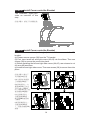
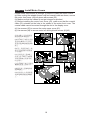
STEP 8 Install the Adapter (Continued)
Please follow instructions below to secure the adapter into place:
(a) First, use screws (31,32) to secure the single hole side of the adapter set
strap (A14) to the inside of the motor front cover.
(b) Peel the backing off one side of the double-sided foam tape (A7). Adhere
the tape onto the smooth side of the adapter (33). Note: Do not cover the
writing on the adapter.
(c) Peel the backing off the other side of the tape (A7) on the adapter (33).
Then place the adapter (33) between the two holes on the motor front cover.
(d) Select a suitable hole in the adapter set strap (A14).
Then use screws (31,32) to secure the adapter (33) into place.
(e) Cut off the excess part of the adapter set strap (A14).
組裝步驟八 濾波器定位安裝說明 請依圖示順序組裝:
(a) 先將濾波器固定帶(A14)單孔的一邊用螺絲(31,32)鎖緊在馬達蓋前板內側上。
(b) 將雙面泡棉膠帶
(A7)一面撕掉,貼
在濾波器(33)的光
滑面上。(注意:不
可貼在文字面上)。
(c) 先將濾波器(33)
上的雙面泡棉膠帶
(A7)離形紙撕掉,
再將濾波器(33)黏
在馬達蓋前板內側
兩孔之間。
(d) 最後將濾波器
固定帶(A14)取適當
孔位,再將濾波器
(33)用螺絲(31,32)
鎖緊。
(e) 剪掉多餘的固定
帶(A14)剪掉。

17
STEP 9 Install the Power Cord
Please install the power cord as shown.
(a) Plug the power cord into the adapter (33).
(b) Use screws (47) and cable clips (48) to secure the power cord and coaxial
cable into place. Note: The curve in the cables cannot protrude past the area
indicated by the arrow. Otherwise, the cables would interfere with unit instal-
lation. Feed the power cord (53) and coaxial cable out the slot in the bottom
of the front cover as shown.
組裝步驟九 電源線定
位安裝 請依圖示順序
組裝:
(a) 將電源線接頭接於
濾波器ADAPTER(33)
。
(b) 利用螺絲(47)與電
線固定扣(48),將電源
線與TV端子線固定於
適當位置(注意:電源線
折彎繞線長度不可過,
最大折彎長度到箭頭
所指的位置,否則裝回
機台時可能有干涉),且
將電源線(53)與TV端
子線繞經馬達蓋前板
底面缺口位置。
(a)
(b)

18
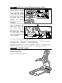
STEP 10 Install Motor Covers
Please follow instructions (a) through (e) below to install the motor covers.
(a) After routing the adapter power cord and coaxial cable as shown, secure
the motor front cover (44) into place with screws (52).
(b) Make sure that the cables do not get crimped or pinched.
(c) Before installing the motor front cover (43), make sure that the coaxial
cable (53) extends out the hole in the middle of the motor front cover. The
coaxial cable cannot be routed through the slot in the display cover.
(d) Use screws (50) to secure the motor upper cover (43).
(e) Use screws (49) to secure motor left and right side covers (41)(42).
組裝步驟十 組裝馬達蓋
請依順序(a~e)組裝:
(a) 將TV端子線置於馬達
蓋前板(44)缺口內,將馬
達蓋前板(44)與螺絲(52)
鎖上。
(b) 蓋上馬達蓋前板之後,
需注意:電源線與訊號線
不可夾線。
(c) 組裝馬達上蓋(43)之
前須注意:TV端子線(53)
須繞經總機台前側中間
的空間內。
(注意:TV端子線不可繞經
儀錶板遮蓋上面缺口)。
(d) 將馬達上蓋(43)與螺
絲(50)鎖上。
(e) 最後將左右馬達側蓋
表(41)(42)與螺絲(49)鎖
上。
(a)
(c)
(e)
(b)
(d)

19
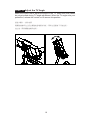
STEP 11 Adjust the TV Angle
Raise the control rod to adjust the angle of the TV. Make sure that cables
do not get pulled during TV angle adjustment. When the TV angle suits your
preference, release the control rod to secure this position.
組裝步驟十一 操作說明
將調整控制桿往上扳去調整液晶電視的角度,同時注意插線不可被拉到。
定位後,再將調整控制桿放開。
-
 1
1
-
 2
2
-
 3
3
-
 4
4
-
 5
5
-
 6
6
-
 7
7
-
 8
8
-
 9
9
-
 10
10
-
 11
11
-
 12
12
-
 13
13
-
 14
14
-
 15
15
-
 16
16
-
 17
17
-
 18
18
-
 19
19
-
 20
20


他の言語で
- English: SportsArt T672 Owner's manual
その他のドキュメント
-
Sony HT-CT350 ユーザーマニュアル
-
Sony KDL-42W670A ユーザーマニュアル
-
Sony Bravia KDL-32W600A Operating Instructions Manual
-
JVC KA-F5602U ユーザーマニュアル
-
Supermicro SuperChassis 732G-903B ユーザーマニュアル
-
Yamaha S12 取扱説明書
-
Tascam DA-98HR ユーザーマニュアル
-
-
Pioneer S-ST330 Operating Instructions Manual
-