ABB ACS880-01-038A-5 Quick Installation Manual
- タイプ
- Quick Installation Manual

—
ABB
工业传动
快速安装指导
ACS880-01
传动
外形尺寸
R1
至
R3
中文 . . . . . . . . . . 5
英文 . . . . . . . . . . 9
R0-
R4
R5
CN
EN

相关手册列表
您可以在 Internet 上查找 PDF 格式的手册和其它产品文件。请参阅封底内的 Internet
上的文件库
一
节。对于在 “ 文档 ” 资料库内没有提供的手册,请联络当地的 ABB 代表。
传动硬件手册和指导 代码 ( 英文 )
ACS880-01
硬件手册
3AUA0000078093
ACS880-01
外形尺寸
R1
至
R3
快速安装指导
3AUA0000085966
ACS-AP
助手控制盘用户手册
3AUA0000085685
传动固件手册和指导
ACS880
主控制程序固件手册
3AUA0000085967
ACS880
传动主控制程序的快速启动指导
3AUA0000098062
可选件手册和指导
I/O
扩展模块
,
现场总线适配器等手册和快速指导
版本 A 中文
基于 3AUA0000085966 版本 A 英文
生效日期:2013-09-01
2013 北京 ABB 电气传动系统有限公司

3
Figures
A
B
空气流量
(m
3
/h)
损耗
(W)
ACS880-01-02A4-5 44 30 OFAF000H4
ACS880-01-03A3-5 44 40 OFAF000H6
ACS880-01-04A0-5 44 52 OFAF000H6
ACS880-01-05A6-5 44 73 OFAF000H10
ACS880-01-07A2-5 44 94 OFAF000H10
ACS880-01-09A4-5 44 122 OFAF000H16
ACS880-01-12A6-5 44 172 OFAF000H16
ACS880-01-017A-5 88 232 OFAF000H25
ACS880-01-025A-5 88 337 OFAF000H32
ACS880-01-032A-5 134 457 OFAF000H40
ACS880-01-038A-5 134 562 OFAF000H50
× 4
× 4
× 4
× 4
1 2 3
5
4
< 40 °C
M5
C
D
L1 L2 L3 T1/U T2/V T3/W
UDC+
R+
UDC-
R-
L1 L2 L3PE
ACS880-01
PE
U1
V1
W1
3 ~ M
2
1
1
3
4

4
E
T3/W
T2/V
T1/U
UDC-
R+
R-
L3
L2
L1
L1, L2, L3, T1/U,
T2/V, T3/W, R-, R+/
UDC+, UDC
(N·m) (N·m)
R1 0.6 1.8
R2 0.6 1.8
R3 1.7 1.8
8
7
6
7
8
9
5
PE
10
F
G
a
b
b > 1/5 · a
12
T3/W
T2/V
T1/U
UDC-
R+
R-
L3
L2
L1
1.5 N·m
0.5 N·m
3AUA0000085966 Rev A

CN –
快速安装指南
5
CN
DA
DE
ES
FI
FR
IT
NL
PT
RU
SV
TR
CN
CN – 快速安装指南
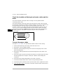
本指南简要的介绍了如何安装传动。更多详细说明、工程指导、技术数据和完整的安
全说明,请参考硬件手册 (www.abb.com/drives: 选择 Document Library 并搜索文档
代码 3AUA0000078093 [ 英文 ])。
遵守以下安全指导
放置传动的地板材料必须为不易燃材料。
选择功率电缆
根据当地规则选择功率电缆,满足传动上的型号指定标签给出的额定电流。
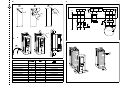
确保冷却
传动的热量损耗和冷却空气流量,请参见第 3 页中的表格 B 。在无需降容的情况下,
允许的传动运行温度范围为 -15 至 +40 °C。
保护传动和电源电缆
参见第 3 页表格 B 中的 ABB 生产的熔断器 。
壁挂式安装传动
参见第 3 页中的图 A 。
警告 ! 忽略以下安全指导会导致人身伤害或伤亡事故、或损坏设备。
• 只有具备资质的电气工程师才可以对传动进行安装和维护。
• 不能对带电的传动、电机电缆或电机进行任何操作。对传动、电机或电机电缆
进行操作前,要断开电源后等待 5 分钟,使中间电路电容器放电。
• 当传动或外部控制电路带电时,不要对控制电缆进行操作。
• 安装时 , 确保钻孔或摩擦的灰尘不能进入传动内部。
3AUA0000085966 Rev A

6 CN –
快速安装指南
EN
DA
DE
ES
FI
FR
IT
NL
PT
RU
SV
TR
CN
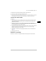
检查电机、输入电缆和电机电缆的绝缘性
连接传动前,根据当地规则检查输入电缆的绝缘性。
当断开传动电缆时,检查电机电缆和电机的绝缘性。使用 500 V 直流测量电压测量每
个相导体和保护接地导体之间的绝缘电阻。 ABB 电机的绝缘电阻必须超过 100 Mohm
( 参考值在 25 °C 或 77 °F 下 )。其它电机的绝缘电阻,请参考其制造说明书。注意: 电
机壳内潮湿会降低绝缘电阻。如果潮湿,将电机进行干燥,并重新测量。
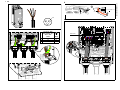
连接功率电缆
参见图 C, D, E 和 F。电机电缆使用对称屏蔽电缆。
1. 松开盖板侧面的两个紧固螺丝。
2. 向前滑动盖板,将其取下。
3. 将标有当地语言的电压警告标签粘贴到控制盘安装板上。
4. 将橡胶垫圈从引线板上取下,用于电缆连接。
5. 将电缆连接器 (包括在发货的塑料袋中 )紧固在电缆引线板孔上。剥开电缆末端。将
电缆穿过连接器。
6. 在电缆连接器中,将电缆屏蔽层 360 度接地。
7. 将电缆双绞屏蔽层连接到接地端子。
8. 连接输入电缆和电机电缆的相导线。紧固螺丝。
9.
单元带有可选件 +D150: 将制动电阻电缆的导线连接到 R+ 和 R- 端子。
10.在分线盒中安装控制电缆接地支架。
11. 确保电缆安装在传动外部。
12.将电机电缆屏蔽层在电机端接地。 基于最小干扰,将电缆引线 360 度接地,或者使
引线尽量短。
连接控制电缆
参见图 G。
ohm
M
3~
U1
V1
W1
PE

CN –
快速安装指南
7
CN
DA
DE
ES
FI
FR
IT
NL
PT
RU
SV
TR
CN
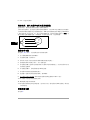
1. 在橡胶垫圈上打足够大的孔,将橡胶垫圈套到电缆上。将电缆穿过底板上的孔,
并将橡胶垫圈贴在孔上。
2. 将电缆末端剥开,切成适当的长度 ( 注意接地导体的额外长度 )。将分线盒中接地
夹子下的所有控制电缆的外部屏蔽层 360 度接地。
3. 将电缆双绞线的屏蔽层与接地夹子连接接地。将屏蔽层的另一端断开或通过一些
毫微法高频电容将其间接接地,如 3.3 nF / 630 V。
4. 将导体连接到控制板上相对应的端子 ( 参见第 8 页 )。
5. 更换盖板。
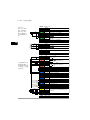
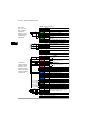
默认 I/O 连接
ACS880 工业控制程序的默认 I/O 连接如下。

8 CN –
快速安装指南
EN
DA
DE
ES
FI
FR
IT
NL
PT
RU
SV
TR
CN
故障
XPOW 外部输入电源
1 +24VI
24 V DC, 2 A
2 GND
XAI 参考电压和模拟输入
1 +VREF 10 V DC, R
L
1…10 kohm
2 -VREF -10 V DC, R
L
1…10 kohm
3 AGND 接地
4 AI1+
速度给定 0(2)…10 V, R
in
> 200 kohm
5 AI1-
6 AI2+
默认未使用。 0(4)…20 mA, R
in
>
100 ohm
7 AI2-
J1 J1 AI1 电流 / 电压选择跳线
J2 J2 AI2 电流 / 电压选择跳线
XAO 模拟输出
1 AO1
电机速度 rpm 0…20 mA, R
L
< 500 ohm
2 AGND
3 AO2
电机电流 0…20 mA, R
L
< 500 ohm
4 AGND
XD2D 传动对传动连接
1 B
传动对传动连接
2 A
3 BGND
J3 J3 传动对传动连接终端跳线
XRO1, XRO2, XRO3 继电器输出
1 NC
准备
250 V AC / 30 V DC
2 A
2 COM
3 NO
1 NC
运行
250 V AC / 30 V DC
2 A
2 COM
3 NO
1 NC
故障 (-1)
250 V AC / 30 V DC
2 A
2 COM
3 NO
XD24 数字互锁
1 DIIL 默认未使用。
2 +24VD +24 V DC 200 mA
1)
3 DICOM 数字输入接地
4 +24VD +24 V DC 200 mA
1)
5 DIOGND 数字输入 / 输出接地
J6 接地选择开关
XDIO 数字输入 / 输出
1 DIO1 输出 : 准备
2 DIO2 输出 : 运行
XDI 数字输入
1 DI1 停止 (0) / 启动 (1)
2 DI2 正转 (0) / 反转 (1)
3 DI3 复位
4 DI4 加速 & 减速选择
5 DI5 恒速选择
6 DI6 数字输入 6 或者热敏电阻输入
XSTO 安全力矩中断
1 OUT1
安全力矩中断。两个电路必须闭合以备
传动启动。
2 SGND
3 IN1
4 IN2
X12 安全功能模块连接
X13
控制盘连接
X205
存储单元连接
电缆尺寸:
0.5 … 2.5 mm
2
(24…12 AWG)
紧固力矩:0.5
N·m (5 lbf·in) 用
于标准和固体导
线。
1)
这些输出的总负
载容量为 4.8 W
(200 mA / 24 V) 减
去安装板上可选模
块的功率。

EN – Quick installation guide 9
EN
DA
DE
ES
FI
FR
IT
NL
PT
RU
SV
TR
CN
EN – Quick installation guide
This guide instructs briefly how to install the drive. For more detailed instructions,
engineering guide lines, technical data and complete safety instructions, see the
hardware manual (www.abb.com/drives
: Select Document Library and search for
document number 3AUA0000078093 [English]).
Follow the safety instructions
The floor material below the drive must be non-flammable.
Select the power cables
Size the power cables according to local regulations to carry the nominal current
given on the type designation label of your drive.
Ensure the cooling
See table B on page 3 for the losses and the cooling air flow through the drive. The
allowed operating temperature range of the drive without derating is -15 to +40 °C.
Protect the drive and input power cable
See fuses manufactured by ABB in table B on page 3.
Install the drive on the wall
See figure A on page 3.
WARNING! Ignoring the following instructions can cause physical injury or
death, or damage to the equipment:
• Only qualified electricians are allowed to install and maintain the drive.
• Never work on the drive, motor cable or motor when main power is applied.
After disconnecting the input power, always wait for 5 min to let the intermediate
circuit capacitors discharge before you start working on the drive, motor or
motor cable.
• Do not work on the control cables when power is applied to the drive or to the
external control circuits.
• Make sure that dust from borings and grindings does not enter the drive when
installing.
3AUA0000085966 Rev A

10 EN – Quick installation guide
EN
DA
DE
ES
FI
FR
IT
NL
PT
RU
SV
TR
CN
Check the insulation of the input and motor cables and the
motor
Check the insulation of the input cable according to local regulations before
connecting it to the drive.
Check the insulation of the motor cable and motor when the cable is disconnected
from the drive. Measure the insulation resistance between each phase conductor and
the Protective Earth conductor using a measuring voltage of 500 V DC. The
insulation resistance of an ABB motor must exceed 100 Mohm (reference value at
25 °C or 77 °F). For the insulation resistance of other motors, please consult the
manufacturer’s instructions. Note: Moisture inside the motor casing will reduce the
insulation resistance. If moisture is suspected, dry the motor and repeat the
measurement.
Connect the power cables
See figures C, D, E and F. Use symmetrical shielded cable for motor cabling.
1. Undo the two fastening screws at the sides of the front cover.
2. Remove the cover by sliding it forward.
3. Attach the residual voltage warning sticker of the local language to the control
panel assembly plate.
4. Remove the rubber grommets from the lead-through plate for the cables to be
connected.
5. Fasten the cable connectors (included in the delivery in a plastic bag) to the cable
lead-through plate holes. Strip the cable ends. Slide the cables through the
connectors.
6. Ground the cable shields 360-degrees in the cable connectors.
7. Connect the twisted shields of the cables to the grounding terminals.
8. Connect the phase conductors of the input and motor cables. Tighten the screws.
9. Units with option +D150:
Connect the conductors of brake resistor cable to the R+
and R- terminals.
ohm
M
3~
U1
V1
W1
PE

EN – Quick installation guide 11
EN
DA
DE
ES
FI
FR
IT
NL
PT
RU
SV
TR
CN
10.Install the control cable grounding shelf in the cable entry box.
11. Secure the cables mechanically outside the drive.
12.Ground the motor cable shield at the motor end. For minimal interference, make a
360-degree grounding at the cable lead-through, or keep the pig tail short.
Connect the control cables
See figure G.
1. Cut adequate holes into the rubber grommets and slide the grommets onto the
cables. Slide the cables through the holes of the bottom plate and attach the
grommets to the holes.
2. Strip the cable ends and cut to suitable length (note the extra length of the
grounding conductors). Ground the outer shields of all control cables 360 degrees
at a grounding clamp in the cable entry box.
3. Ground the pair-cable shields to the grounding clamp. Leave the other end of the
shields unconnected or ground them indirectly via a few nanofarads high-
frequency capacitor, eg, 3.3 nF / 630 V.
4. Connect the conductors to the appropriate terminals of the control board (see
page 12).
5. Replace the front cover.
Default I/O connections
Default I/O connections of ACS880 industrial control program are shown below.

12 EN – Quick installation guide
EN
DA
DE
ES
FI
FR
IT
NL
PT
RU
SV
TR
CN
Fault
XPOW External power input
1 +24VI
24 V DC, 2 A
2 GND
XAI Reference voltage and analog inputs
1 +VREF 10 V DC, R
L
1…10 kohm
2 -VREF -10 V DC, R
L
1…10 kohm
3 AGND Ground
4 AI1+ Speed reference 0(2)…10 V, R
in
>
200 kohm
5 AI1-
6 AI2+
By default not in use. 0(4)…20 mA, R
in
>
100 ohm
7 AI2-
J1 J1 AI1 current/voltage selection jumper
J2 J2 AI2 current/voltage selection jumper
XAO Analog outputs
1 AO1 Motor speed rpm 0…20 mA, R
L
<
500 ohm
2 AGND
3 AO2
Motor current 0…20 mA, R
L
< 500 ohm
4 AGND
XD2D Drive-to-drive link
1 B
Drive-to-drive link
2 A
3 BGND
J3 J3 Drive-to-drive link termination switch
XRO1, XRO2, XRO3 Relay outputs
1 NC
Ready
250 V AC / 30 V DC
2 A
2 COM
3 NO
1 NC
Running
250 V AC / 30 V DC
2 A
2 COM
3 NO
1 NC
Faulted(-1)
250 V AC / 30 V DC
2 A
2 COM
3 NO
XD24 Digital interlock
1 DIIL By default not in use.
2 +24VD +24 V DC 200 mA
1)
3 DICOM Digital input ground
4 +24VD +24 V DC 200 mA
1)
5 DIOGND Digital input/output ground
J6 Ground selection switch
XDIO Digital input/outputs
1 DIO1 Output: Ready
2 DIO2 Output: Running
XDI Digital inputs
1 DI1 Stop (0) / Start (1)
2 DI2 Forward (0) / Reverse (1)
3 DI3 Reset
4 DI4 Acceleration & deceleration select
5 DI5 Constant speed select
6 DI6 By default not in use.
XSTO Safe torque off
1 OUT1
Safe torque off. Both circuits must be
closed for the drive to start.
2 SGND
3 IN1
4 IN2
X12 Safety functions module connection
X13 Control panel connection
X205 Memory unit connection
Wire sizes:
0.5 … 2.5 mm
2
(24…12 AWG)
Tightening
torques: 0.5 N·m
(5 lbf·in) for both
stranded and
solid wiring.
1)
Total load
capacity of these
outputs is 4.8 W
(200 mA / 24 V)
minus the power
taken by the option
modules installed
on the board.

更多信息
产品和服务咨询
用户想了解关于本产品的任何信息,均可与当地的 ABB 代表处联系,在咨询时请提
供产品的型号和要咨询的产品的序列号。要了解 ABB 销售商、技术支持和服务的列
表,可以登录网页 www.abb.com/drives
,并选择
销售
、
支持和服务网络
。
产品培训
要了解 ABB 产品培训信息,请登录网页 www.abb.com/drives,并选择
培训课程
。
提供关于 ABB 传动手册的反馈信息
欢迎您针对我们的手册提出宝贵意见。访问网页 www.abb.com/drives,选 择
文件库
-
手册反馈表
(LV AC
传动
)。
Internet 上的文件库
您可以在 Internet 上查找 PDF 格式的手册和其它产品文件。请登录网页
www.abb.com/drives
,并选择
文件库
。您可以浏览文件库或在搜索字段中输入选择标
准,例如文件代码。

—
全国各地区销售代表处联系方式
上海办事处
中国
上海市
200001
上海市黄浦区蒙自路
763
号丰盛
创建大厦
16
层
电话
:
+86 21 2328 8888
传真
:
+86 21 2328 8678
沈阳办事处
中国
辽宁省沈阳市
110001
和平区南京北街
206
号假日城市
广场
2
座
16
层
电话
:
+86 24 3132 6688
传真
:
+86 24 3132 6699
乌鲁木齐办事处
中国
新疆乌鲁木齐市
830002
中山路
339
号中泉广场国家开发
银行大厦
6B
电话
:
+86 991 283 4455
传真
:
+86 991 281 8240
重庆办事处
中国
重庆市
400021
北部新区星光大道
62
号海王星科
技大厦
A
区
6
层
电话
:
+86 023 6788 5732
传真
:
+86 023 6280 5369
深圳办事处
中国
广东省深圳市
518031
深圳市福田区华富路
1018
号中航
中心
1504A
电话
:
+86 755 8831 3038
传真
:
+86 755 8831 3033
杭州办事处
中国
浙江省杭州市
310000
杭州市钱江路
1366
号华润大厦
A
座
8
层
电话
:
+86 571 8763 3967
传真
:
+86 571 8790 1151
长沙办事处
中国
湖南省长沙市
410005
黄兴中路
88
号平和堂商务楼
12B01
电话
:
+86 731 8268 3005
传真
:
+86 731 8444 5519
广州办事处
中国
广州市
519623
珠江新城珠江西路
15
号珠江城大
厦
29
楼
01-06A
单元
电话
:
+86 20 3785 0688
传真
:
+86 20 3785 0608
成都办事处
中国
四川省成都市
610041
人民南路四段三号来福士广
场
T1-8
层
电话
:
+86 28 8526 8800
传真
:
+86 28 8526 8900
厦门办事处
中国
福建省厦门市
361009
湖里火炬高新区信息光电园围里
路
559
号
电话
:
+86 592 630 3058
传真
:
+86 592 630 3531
昆明办事处
中国
云南省昆明市
650032
昆明市崇仁街
1
号东方首座
2404
室
电话
:
+86 871 6315 8188
传真
:
+86 871 6315 8186
郑州办事处
中国
河南省郑州市
450007
中原中路
220
号裕达国际贸易中
心
A
座
1006
室
电话
:
+86 371 6771 3588
传真
:
+86 371 6771 3873
贵阳办事处
中国
贵州省贵阳市
550022
观山湖区金阳南路
6
号世纪金源
购物中心
5
号楼
10
层
电话
:
+86 851 8221 5890
传真
:
+86 851 8221 5900
西安办事处
中国
陕西省西安市
710075
西安市经济技术开发区文景路中
段
158
号
3
层
电话
:
+86 29 8575 8288
传真
:
+86 29 8575 8299
武汉办事处
中国
湖北省武汉市
430060
武昌区临江大道
96
号武汉万达
中心
21
层
电话
:
+86 27 8839 5888
传真
:
+86 27 8839 5999
福州办事处
中国
福建省福州市
350028
仓山万达广场
A1
座
706-709
室
电话
:
+86 591 8785 8224
传真
:
+86 591 8781 4889
哈尔滨办事处
中国
黑龙江省哈尔滨市
150090
哈尔滨市南岗区长江路
99-9
号辰
能大厦
14
层
电话
:
+86 451 5556 2291
传真
:
+86 451 5556 2295
兰州办事处
中国
甘肃省兰州市
730030
兰州市城关区张掖路
87
号
中广大厦
23
楼
电话
:
+86 931 818 6466
传真
:
+86 931 818 6755
济南办事处
中国
山东省济南市
250011
泉城路
17
号华能大厦
6
楼
8601
室
电话
:
+86 531 8609 2726
传真
:
+86 531 8609 2724
ABB
传动官方微信
ABB
传动电子资料库
© Copyright 2016 ABB
版权所有
3ABD00045454
版本
A
中文
基于
3AUA0000085966
版本
A
英文
生效日期
:
2013-09-01
北京
ABB
电气传动系统有限公司
中国
,
北京
,
100015
北京市朝阳区酒仙桥北路甲
10
号
401
楼
电话
:
+86 10 58217788
24
小时
×
365
天技术热线
:
+86 400 810 8885
网址
:
www.abb.com/drives
—
联系我们
-
 1
1
-
 2
2
-
 3
3
-
 4
4
-
 5
5
-
 6
6
-
 7
7
-
 8
8
-
 9
9
-
 10
10
-
 11
11
-
 12
12
-
 13
13
-
 14
14


ABB ACS880-01-038A-5 Quick Installation Manual
- タイプ
- Quick Installation Manual
他の言語で
- English: ABB ACS880-01-038A-5