
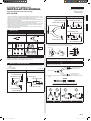
En-1
Gas pipe Reducer
I.D ø34.92 (1-3/8)
I.D ø41.28 (1-5/8)
I.D ø41.28 (1-5/8)
I.D ø41.28 (1-5/8)
O.D ø41.28 (1-5/8)
I.D ø28.58 (1-1/8)
I.D ø28.58 (1-1/8)
I.D ø44.45 (1-3/4)
O.D ø41.28 (1-5/8)
I.D ø50.8 (2)
O.D ø34.92 (1-3/8)
I.D ø34.92 (1-3/8)
(2) Select the connections with the pipe diameters that match the selected pipe sizes
from the separation tubes, and cut them with a pipe cutter.
Branch kit
Field pipe
Connections
Standard cutting position:
1/2L
+3
-0
mm
NOTE:
Insert the field pipe firmly until it touches the joint pipe (Branch kit).
CAUTION
Use a pipe cutter to cut a pipe. Point the pipe downward while deburring so that cutting
chips will not enter inside the pipe.
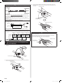
(3) The installation direction for the branch kit is shown as follows.
To indoor units
To outdoor unit or out-
door unit branch kit
To outdoor unit or out-
door unit branch kit
(4) Place the separation tubes horizontally or vertically so that the refrigerant separates
evenly.
GOOD
Horizontal
PROHIBITED
• This manual describes the “Installation Specifications for Separation Tube Kits”. For the
“outdoor unit”, refer to the installation manual supplied with the outdoor unit, and for the
“indoor unit”, refer to the installation manual supplied with the indoor unit.
• Please read this manual thoroughly prior to installation, and perform the installation work
in accordance with the instructions.
• Before performing the installation work, thoroughly read the “Safety Precautions” in the
installation manual supplied with the outdoor unit, and work accordingly.
• After installing the unit, perform a test run to make sure the unit operates normally. Then,
explain to the customer how to operate and maintain the unit in accordance with the
operating manual (supplied with the indoor unit).
• Hand this manual, together with the operating manual, to the customer. Request the
customer to keep them on hand.
1. PARTS LIST
Liquid pipe Gas pipe
Reducer Insulation Tape
For liquid
pipe
8 pcs.
For gas
pipe
2. SELECTION PROCEDURE
For details on the selection of the separation tube kits, refer to the installation manual
supplied with the outdoor unit or the Design & Technical manual.
3. INSTALLATION PROCEDURE
(1) The following table shows the sizes of the inlet and outlet pipes of the connection
pipes.
I.D.: Inner diameter
O.D.: Outer diameter Unit: mm (in)
Liquid pipe Reducer
I.D ø22.22 (7/8)
I.D ø25.4 (1)
I.D ø15.88 (5/8)
I.D ø15.88 (5/8)
I.D ø19.05 (3/4)
I.D ø19.05 (3/4)
I.D ø19.4 (3/4)
O.D ø22.22 (7/8)
I.D ø12.93 (1/2)
O.D ø15.88 (5/8)
PART No. 9371636313-02
Original instruction
MADE IN P.R.C.
English
中 文
OUTDOOR UNIT BRANCH KIT
INSTALLATION MANUAL
For authorized service personnel only.
UTP-CX792B

En-2
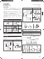
CAUTION
Keep the angle of the connection pipe as following figure. Otherwise, it will not separate
the refrigerant evenly, causing a reduction in performance.
GOOD:
0° to -10°
GOOD:
0° to -5°
PROHIBITED
PROHIBITED
PROHIBITED
PROHIBITED
• During piping work, apply nitrogen gas while brazing the pipes. If pipes are brazed
without applying nitrogen gas, it will create a large amount of oxidation film, which will
cause a critical malfunction.
• To prevent moisture or foreign matter from entering during work, do not leave the
piping open.
• Refer to the Installation Manual supplied with the outdoor unit for airtightness test and
evacuation procedures.
About the connecting curvature of field pipe and branch kit:
The field pipe should be connected to the branch kit so that the curved angle on each
side is 3 degree or less.
* 0 to 26 mm
(0 to 1 in.)
* 0 to 26 mm
(0 to 1 in.)
0.5 m (19-11/16 in.)
3°
3°
*: Allowed value based on “A” (center of field pipe) at 0.5 m (19-11/16 in.) from “B”
(junction of the branch kit).
If the field pipe is connected with angle larger than specified, the balance of split refrig-
erant flow will be lost, and the refrigerant may concentrate upon specific outdoor unit as
shown in the following figure. Such unbalanced refrigerant flow may cause a compres-
sor malfunction.
Outdoor unit 1
(Master)
Compressor
malfunction
Little refrigerant
Too much
refrigerant
Outdoor unit 2
(Slave 1)
Outdoor unit 3
(Slave 2)
Outdoor unit 4
(Slave 3)
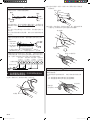
4. After brazing the pipes, use the supplied insula-
tion to insulate them.
(1) Remove the protective sheet from the double-stick tape that is affixed to the heat
insulation.
Double-stick tapes
(2) Be sure to install the tape (Accessory) in each heat insulation to the 2 positions as
shown in the following figure.
Tapes (accessories)
(3) Use tape (locally purchased) to seal the seam so that there will be no gap at the
junction between the aforementioned heat insulation and the heat insulation on the
local piping.
Tapes (locally purchased)
Contact each other
Insulations
(locally purchased)
CAUTION
Insulate the liquid and gas pipe completely. If not, it may cause the water condensation
or performance reduction.
• Wrap the heat insulation with tape or pipe cover in order to extend the life time of heat insulation.
(a) Environment temperature ≥ 35°C (95°F) and humidity 85%.
(b) Environment temperature ≥ 25°C (77°F) and humidity 90%.
Heat insulation
(locally purchased)
Installation example

Sc-1
气管 异径管
I.D ø34.92 (1-3/8)
I.D ø41.28 (1-5/8)
I.D ø41.28 (1-5/8)
I.D ø41.28 (1-5/8)
O.D ø41.28 (1-5/8)
I.D ø28.58 (1-1/8)
I.D ø28.58 (1-1/8)
I.D ø44.45 (1-3/4)
O.D ø41.28 (1-5/8)
I.D ø50.8 (2)
O.D ø34.92 (1-3/8)
I.D ø34.92 (1-3/8)
(2) 从分歧管中选择管道直径与所选管道尺寸相匹配的接头
并用管道切割工具对其进行切割。
分流部件
现场管道
接头
标准切割位置:
1/2L
+3
-0
mm
注
:
插入现场管道,直到其接触到接合管(分流部件)。
注意
用管道切割工具切割管道。去除毛刺时应将管道朝下放
置,以防切割碎片进入管道内部。
(3) 分流部件的安装方向如下所示。
至室内机
至室外机或室
外机分流部件
至室外机或室
外机分流部件
(4) 将分歧管水平或垂直放置,以使制冷剂均匀分歧。
良好
水平
禁止
• 本说明书介绍了“分歧管组件的安装规范”。关于“室外
机”的详细信息,请参考室外机随附的安装说明书;而关
于“室内机”的详细信息,请参考室内机随附的安装说明
书。
• 请在安装之前仔细阅读本说明书并根据本说明书上的说明
进行安装。
• 在进行安装之前,请仔细阅读室外机随附安装说明书中的
“安全注意事项”,按要求进行安装。
• 安装机组之后,请执行试运行以确保机组运行正常。然
后,根据(室内机附带的)使用说明书向用户说明如何操
作和维护机组。
• 将本说明书与使用说明书一起交给用户。要求用户妥善保
管。
1. 部件列表
液管 气管
异径管 绝缘材料 胶带
用于
液管
8件
用于
气管
2. 选择步骤
有关分歧管组件选择的详细信息,请参见室外机附带的安
装说明书或设计和技术说明书。
3. 安装步骤
(1) 下表列出了连接管的入口管和出口管的尺寸。
I.D.:内径
O.D.:外径 单位:mm(in.)
液管 异径管
I.D ø22.22 (7/8)
I.D ø25.4 (1)
I.D ø15.88 (5/8)
I.D ø15.88 (5/8)
I.D ø19.05 (3/4)
I.D ø19.05 (3/4)
I.D ø19.4 (3/4)
O.D ø22.22 (7/8)
I.D ø12.93 (1/2)
O.D ø15.88 (5/8)
部件编号9371636313-02
中国制造
室外机分流部件
安装说明书
仅供授权的维修人员使用。
UTP-CX792B
中 文

Sc-2
注意
将连接管的角度保持在下图所示范围内。否则,制冷剂将
无法均匀分歧,从而导致性能降低。
良好:
0°至-10°
良好:
0°至-5°
禁止
禁止
禁止
禁止
• 管道作业期间,进行管道铜焊时要使用氮气。如果进行管
道铜焊时不使用氮气,将产生大量氧化膜,从而导致严重
故障。
• 为了防止在作业期间进入水分或异物,请勿使管道处于打
开状态。
• 有关气密试验和抽真空的步骤,请参见室外机附带的安装
说明书。
关于现场管道和分流部件的连接曲率:
现场管道应连接到分流部件,使得每侧的弯曲角度为3度
或以下。
* 0至26 mm
(0至1 in.)
* 0至26 mm
(0至1 in.)
0.5 m (19-11/16 in.)
3°
3°
*: 允许值以距离“B(分流部件的接头)”0.5 m
(19-11/16 in.) 的“A”(现场管道的中心)为基础。
如果现场管道的连接角度大于指定角度,分离制冷剂流量
的平衡将被打破,制冷剂可能会如图所示集中在某台室外
机处。这种不平衡的制冷剂流可能会造成压缩机故障。
室外机1
(主机)
压缩机故障
制冷剂太少
制冷剂太多
室外机2
(子机1)
室外机3
(子机2)
室外机4
(子机3)
4. 在对管道进行铜焊后,应使用附带的绝热材
料对其进行绝热处理。
(1) 拆下保温材料上粘贴的双面胶上的保护层。
双面胶
(2) 请务必将胶带(附件)粘贴在如下图所示的每个保温材
料的两处。
胶带(附件)
(3) 用胶带(本地采购)将接合处密封,使上述保温材料和
当地管道上的保温材料之间的连接处不留缝隙。
胶带(本地采购)
相互接触
绝缘材料
(本地采购)
注意
对液管和气管进行完全绝热。否则,可能会导致冷凝水形
成或性能降低。
• 用胶带或管罩包裹保温材料,以延长保温材料的使用寿
命。
(a)环境温度≥ 35°C (95°F) 且湿度为85%。
(b)环境温度≥ 25°C (77°F) 且湿度为90%。
保温材料
(本地采购)
安装示例
-
 1
1
-
 2
2
-
 3
3
-
 4
4


