
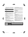
DS18DFL
Cordless Driver Drill
DS 14DFL
•
DS 18DFL
Handling instructions
Read through carefully and understand these instructions before use.

2
3
8
0
9
1
@
#
$
%
!
!
#
^
&
w
e
)
q
&
*
2
2
3
1
6
3
7
5
4
12
(
12
34
56
78

3
r
y
t
y
u
i
p
a
u
u
o
2
3
4
5
1
(A)
910
11 12
13 14
15 16

4
1
14.4 V Rechargeable battery
2
18 V Rechargeable battery
3
Latch
4
Pull out
5
Insert
6
Handle
7
Push
8
Insert
9
Pilot lamp
0
Hole for connecting the rechargeable battery
!
Drill mark
@
Clutch dial
#
Triangle mark
$
Weak
%
Strong
^
Line
&
Shift knob
*
Low speed
(
High speed
)
Ring
q
Sleeve
w
Tighten
e
Loosen
r
Trigger switch
t
Selector button
y
R
L
R
and
L
marks
u
Hook
i
Loosen
o
Spring
p
Larger diameter faces away
a
Driver bit

5

6
○
○
○
○

7
1
2
3

8
○
○
○

9
○
○
○
○
○
○
○

10
○
○
○
○
○
○

11
○
L
R
○
○
○
○
○
○
○
○

12

13
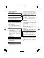
GENERAL SAFETY RULES
WARNING!
Read all instructions
Failure to follow all instructions listed below may result in
electric shock, fi re and/or serious injury.
The term “power tool” in all of the warnings listed below
refers to your mains operated (corded) power tool or battery
operated (cordless) power tool.
SAVE THESE INSTRUCTIONS
1) Work area safety
a) Keep work area clean and well lit.
Cluttered or dark areas invite accidents.
b) Do not operate power tools in explosive
atmospheres, such as in the presence of
fl ammable liquids, gases or dust.
Power tools create sparks which may ignite the dust
or fumes.
c) Keep children and bystanders away while
operating a power tool.
Distractions can cause you to lose control.
2) Electrical safety
a) Power tool plugs must match the outlet.
Never modify the plug in any way.
Do not use any adapter plugs with earthed
(grounded) power tools.
Unmodifi ed plugs and matching outlets will reduce
risk of electric shock.
b) Avoid body contact with earthed or grounded
surfaces, such as pipes, radiators, ranges and
refrigerators.
There is an increased risk of electric shock if your
body is earthed or grounded.
c) Do not expose
power tools to rain or wet
conditions.
Water entering a power tool will increase the risk of
electric shock.
d) Do not abuse the cord. Never use the cord for
carrying, pulling or unplugging the power tool.
Keep cord away from heat, oil, sharp edges or
moving parts.
Damaged or entangled cords increase the risk of
electric shock.
e) When operating a power tool outdoors, use an
extension cord suitable for
outdoor use.
Use of a cord suitable for outdoor use reduces the
risk of electric shock.
3) Personal safety
a) Stay alert, watch what you are doing and use
common sense when operating a power tool.
Do not use a power tool while you are tired
or under the infl uence of drugs, alcohol or
medication.
A moment of inattention while operating power tools
may result in serious personal injury.
b) Use personal protective equipment. Always
wear
eye protection.
Protective equipment such as dust mask, non-skid
safety shoes, hard hat, or hearing protection used for
appropriate conditions will reduce personal injuries.
c) Prevent unintentional starting. Ensure the
switch is in the off -position before connecting to
power source and/or battery pack, picking up or
carrying the tool.
Carrying power tools with your fi nger on the switch or
energising power tools that have the switch on invites
accidents.
d) Remove any adjusting key or wrench before
turning the power tool on.
A wrench or a key left attached to a rotating part of the
power tool may result in personal injury.
e) Do not overreach. Keep proper
footing and
balance at all times.
This enables better control of the power tool in
unexpected situations.
f) Dress properly. Do not wear loose clothing or
jewellery. Keep your hair, clothing and gloves
away from moving parts.
Loose clothes, jewellery or long hair can be caught in
moving parts.
g) If devices are provided for the connection of
dust extraction and collection facilities, ensure
these are connected and properly used.
Use of dust collection can reduce dust related
hazards.
4) Power
tool use and care
a) Do not force the power tool. Use the correct
power tool for your application.
The correct power tool will do the job better and safer
at the rate for which it was designed.
b) Do not use the power tool if the switch does not
turn it on and off .
Any power tool that cannot be controlled with the
switch is dangerous and must be repaired.
c) Disconnect the plug from the power source and/
or the battery
pack from the power tool before
making any adjustments, changing accessories,
or storing power tools.
Such preventive safety measures reduce the risk of
starting the power tool accidentally.
d) Store idle power tools out of the reach of children
and do not allow persons unfamiliar with the
power tool or these instructions to operate the
power tool.
Power tools are dangerous in the hands of untrained
users.
e) Maintain power tools. Check
for misalignment or
binding of moving parts, breakage of parts and
any other condition that may aff ect the power
tools’ operation.
If damaged, have the power tool repaired before
use.
Many accidents are caused by poorly maintained
power tools.
f) Keep cutting tools sharp and clean.
Properly maintained cutting tools with sharp cutting
edges are less likely to bind and are easier to control.
g) Use the power tool, accessories and tool bits
etc. in
accordance with these instructions,
taking into account the working conditions and
the work to be performed.
Use of the power tool for operations diff erent from
those intended could result in a hazardous situation.
5) Battery tool use and care
a) Ensure the switch is in the off position before
inserting battery pack.
Inserting the battery pack into power tools that have
the switch on invites accidents.

14
b) Recharge only with the charger specifi ed by the
manufacturer.
A charger that is suitable for one type of battery pack
may create a risk of fi re when used with another
battery pack.
c) Use power tools only with specifi cally designated
battery packs.
Use of any other battery packs may create a risk of
injury and fi re.
d) When battery pack is not in use, keep it away
from other metal objects like paper clips, coins,
keys, nails, screws, or other
small metal objects
that can make a connection from one terminal to
another.
Shorting the battery terminals together may cause
burns or a fi re.
e) Under abusive conditions, liquid may be ejected
from the battery; avoid contact. If contact
accidentally occurs, fl ush with water. If liquid
contacts eyes, additionally seek medical help.
Liquid ejected from the battery may cause irritation or
burns.
6) Service
a) Have your power tool serviced
by a qualifi ed
repair person using only identical replacement
parts.
This will ensure that the safety of the power tool is
maintained.
PRECAUTION
Keep children and infi rm persons away.
When not in use, tools should be stored out of reach of
children and infi rm persons.
PRECAUTIONS FOR CORDLESS DRIVER
DRILL
1. Always charge the battery at a temperature of 0 – 50°C.
Charging the battery at temperatures outside the range
of 0 – 50°C may prevent proper charging and reduce
battery life.
The most suitable temperature for charging is that of 20 –
25°C.
2. When one charging is completed,
leave the charger for
about 15 minutes before the next charging of battery.
Do not charge the battery more than 2 hours.
3. Do not allow foreign matter to enter the hole for
connecting the rechargeable battery.
4. Never disassemble the rechargeable battery and
charger.
5. Never short-circuit the rechargeable
battery. Short-
circuiting the battery will cause a great electric current
and overheat. It results in burn or damage to the battery.
6. Do not dispose of the battery in fi re.
If the battery is burnt, it may explode.
7. When drilling in wall, fl oor or ceiling, check for buried
electric
power cord, etc.
8. Bring the battery to the shop from which it was purchased
as soon as the post-charging battery life becomes too
short for practical use. Do not dispose of the exhausted
battery.
9. Using an exhausted battery will damage the charger.
10. Do not insert object into the air ventilation slots of the
charger.
Inserting metal objects or infl ammables into the charger
air ventilation slots will result in electrical shock hazard or
damaged charger.
11. When mounting a bit into the keyless chuck, tighten the
sleeve adequately. If the sleeve
is not tight, the bit may
slip or fall out, causing injury.
CAUTION ON LITHIUM-ION BATTERY
This battery is exclusively for the driver drill. Never use
with any other heavy-duty power tools (i.e. Circular saw,
Reciprocating saw, Disc grinder and Blower etc.).
To extend the lifetime, the lithium-ion battery equips with the
protection function to stop the output.
In the cases of 1 to 3
described below, when using this
product, even if you are pulling the switch, the motor may
stop. This is not the trouble but the result of protection
function.
1. When the battery power remaining runs out, the motor
stops.
In such case, charge it up immediately.
2. If the tool
is overloaded, the motor may stop. In this
case, release the switch of tool and eliminate causes of
overloading. After that, you can use it again.
3. If the battery is overheated under overload work, the
battery power may stop.
In this case, stop using the battery and let the
battery
cool. After that, you can use it again.
Furthermore, please heed the following warning and caution.
WARNING
In order to prevent any battery leakage, heat generation,
smoke emission, explosion and ignition beforehand, please
be sure to heed the following precautions.
1. Make sure that swarf and dust do not collect
on the
battery.
○ During work make sure that swarf and dust do not fall on
the battery.
○ Make sure that any swarf and dust falling on the power
tool during work do not collect on the battery.
○ Do not store an unused battery in a location exposed to
swarf
and dust.
○ Before storing a battery, remove any swarf and dust that
may adhere to it and do not store it together with metal
parts (screws, nails, etc.).
2. Do not pierce battery with a sharp object such as a
nail, strike with a hammer, step on, throw or
subject the
battery to severe physical shock.
3. Do not use an apparently damaged or deformed battery.
4. Do not use the battery in reverse polarity.
5. Do not connect directly to an electrical outlets or car
cigarette lighter sockets.
6. Do not use the battery for a purpose other than
those
specifi ed.
7. If the battery charging fails to complete even when a
specifi ed recharging time has elapsed, immediately stop
further recharging.
8. Do not put or subject the battery to high temperatures or
high pressure such as into a microwave oven, dryer, or
high pressure container.
9.
Keep away from fi re immediately when leakage or foul
odor are detected.

15
2. If liquid leaks onto your skin or clothes, wash well with
clean water such as tap water immediately.
There is a possibility that this can cause skin irritation.
3. If you fi nd rust, foul odor, overheating, discolor,
deformation, and/or other irregularities when using the
battery for the fi rst time,
do not use and return it to your
supplier or vendor.
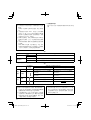
SPECIFICATIONS
POWER TOOL
Model DS14DFL DS18DFL
No-load speed (Low/High) 0 – 400 / 0 – 1200 /min 0 – 400 / 0 – 1200 /min
Capacity
Drilling
Wood
(Thickness 18 mm)
30 mm 38 mm
Metal
(Thickness 1.6 mm)
Steel: 12 mm Steel: 13 mm
Driving
Machine screw 6 mm 6 mm
Wood screw
8 mm (diameter) × 75 mm (length)
(Requires a pilot hole)
8 mm (diameter)
× 75 mm (length)
(Requires a pilot hole)
Rechargeable battery
BCL1415: Li-ion 14.4 V (1.5 Ah 4 cells) BCL1815: Li-ion 18 V (1.5 Ah 5 cells)
Weight
1.6 kg 1.7 kg
CHARGER
Model UC18YGL2
Charging voltage 7.2 – 18 V
Weight 0.4 kg
STANDARD ACCESSORIES
DS14DFL
DS18DFL
1 Plus driver bit (No. 2 × 65L) ................... 1
2 Charger (UC18YGL2) ............................ 1
3 Plastic case ........................................... 1
Standard accessories are subject to change without notice.
OPTIONAL ACCESSORIES (sold separately)
1. Battery (BCL1415) (For DS14DFL)
2. Battery (BCL1815) (For DS18DFL)
Optional accessories are subject to change without notice.
APPLICATIONS
○ Driving and removing of machine screws, wood screws,
tapping screws, etc.
○ Drilling of various woods.
○ Drilling of various metals.
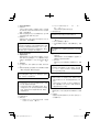
BATTERY REMOVAL/INSTALLATION
1. Battery removal
Hold the handle tightly and push the battery latch to
remove the battery (see Figs. 1 and 2).
CAUTION
Never short-circuit the battery.
2. Battery installation
Insert the battery while observing its polarities (see
Fig. 2).
10. Do not use in a location where strong static electricity
generates.
11. If there is battery leakage, foul odor, heat generated,
discolored or deformed, or in any way appears abnormal
during use, recharging or storage, immediately remove it
from the equipment or battery charger, and stop use.
CAUTION
1. If liquid leaking from the battery gets into your eyes, do not
rub
your eyes and wash them well with fresh clean water
such as tap water and contact a doctor immediately.
If left untreated, the liquid may cause eye-problems.

16
CHARGING
Before using the power tool, charge the battery as follows.
1. Connect the charger power cord to the receptacle
When connecting the plug of the charger to a receptacle,
the pilot lamp will blink in red (At 1-second intervals).
2. Insert the battery in the charger
Firmly insert the battery into
the charger till it contacts
the bottom of the charger and checking the polarities as
shown in Fig. 3.
Regarding electric discharge in case of new batteries, etc.
As the internal chemical substance of new batteries and
batteries that have not been used for an extended period
is not activated, the electric discharge might be low when
using them the fi rst and second time. This is a temporary
phenomenon, and normal time required for recharging
will be restored
by recharging the batteries 2 – 3 times.
How to make the batteries perform longer.
(1) Recharge the batteries before they become completely
exhausted.
When you feel that the power of the tool becomes
weaker, stop using the tool and recharge its battery. If
you continue to use the tool and exhaust the electric
current, the battery may be
damaged and its life will
become shorter.
(2) Avoid recharging at high temperatures.
A rechargeable battery will be hot immediately after use.
If such a battery is recharged immediately after use, its
internal chemical substance will deteriorate, and the
battery life will be shortened. Leave the battery and
recharge it
after it has cooled for a while.
CAUTION:
○ When the battery charger has been continuously used,
the battery charger will be heated, thus constituting
the cause of the failures. Once the charging has been
completed, give 15 minutes rest until the next charging.
○ If the battery is recharged when
it is warm due to battery
use or exposure to sunlight, the pilot lamp may light in
green.
The battery will not be recharged. In such a case,let the
battery cool before charging.
CAUTION
If the batteries are inserted in the reverse direction, not
only recharging will become impossible, but
it may also
cause problems in the charger such as a deformed
recharging terminal.
3. Charging
When inserting a battery in the charger, the pilot lamp will
light up continuously in red.
When the battery becomes fully recharged, the pilot lamp
will blink in red (At 1-second intervals). (See Table
1)
(1) Lamp indication
The indications of the lamp will be as shown in Table
1, according to the condition of the charger or the
rechargeable battery.
Table 1
Indications of the pilot lamp
Pilot lamp
(red)
Before
charging
Blinks
Lights for 0.5 seconds. Does not light for 0.5
seconds. (off for 0.5 seconds)
While
charging
Lights
Lights continuously
Charging
complete
Blinks
Lights for 0.5 seconds. Does not light for 0.5
seconds. (off for 0.5 seconds)
Overheat
standby
Blinks
Lights for 1 second. Does not light for 0.5
seconds. (off for 0.5 seconds)
Battery overheated.
Unable to charge
(Charging will commence
when battery cools).
(2) Regarding the temperatures of the rechargeable battery
The temperatures for rechargeable batteries are as
shown in Table 2, and batteries that have become hot
should be cooled for a while before being recharged.
Table 2 Recharging ranges of
batteries
Rechargeable batteries
Temperatures at which the
battery can be recharged
BCL1415, BCL1815 0°C – 50°C
(3) Regarding recharging time
Depending on the combination of the charger and
batteries, the charging time will become as shown in
Table 3
Table 3 Charging time (At 20°C)
Charger
Battery
UC18YGL2
BCL1415, BCL1815 Approx. 40 min.
NOTE
The charging time may vary according to the ambient
temperature and power source voltage.
4. Disconnect the charger’s power cord from the
receptacle.
5. Hold the charger fi rmly and pull out the battery.
NOTE
Be sure to pull out the battery from the charger after
use,
and then keep it.

17
○ If the battery charger does not work while the battery
is mounted correctly, it is probable that the battery or
charger is malfunctioning. Take it to your authorized
Service Center.
PRIOR TO OPERATION
1. Setting up and checking the work environment
Check if the work environment is suitable by following the
precautions.
HOW TO USE
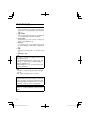
1. Confi rm the clutch dial position (See Fig. 4)
The tightening torque of this unit can be adjusted
according to the clutch dial position, at which the clutch
dial is set.
(1) When using this unit as a screwdriver, line up the one of
the numbers “1, 5, 9 ...
22” on the clutch dial, or the dots,
with the triangle mark on the outer body.
(2) When using this unit as a drill, align the clutch dial drill
mark “
” with the triangle mark on the outer body.
CAUTION
○ The clutch dial cannot be set between the numerals “1, 5,
9 ... 22” or the dots.
○ Do not use with the clutch dial numeral between “22”
and the line at the middle of the drill mark. Doing so may
cause
damage (See Fig. 5).
2. Tightening torque adjustment
(1) Tightening torque
Tightening torque should correspond in its intensity to
the screw diameter. When too strong torque is used,
the screw head may be broken or be injured. Be sure
to adjust the clutch dial position according to the screw
diameter.
(2) Tightening torque indication
The tightening torque diff ers depending on the type of
screw and the material being tightened.
The unit indicates the tightening torque with the numbers
“1, 5, 9 ... 22” on the clutch dial, and a dots. The tightening
toque at position “1” is the weakest
and the torque is
strongest at the highest number (See Fig. 4).
(3) Adjusting the tightening torque
Rotate the clutch dial and line up the numbers “1, 5, 9 ...
22” on the clutch dial, or the dots, with the triangle mark
on the outer body. Adjust the clutch dial in
the weak or the
strong torque direction according to the torque you need.
CAUTION
○ The motor rotation may be locked to cease while the unit
is used as drill. While operating the driver drill, take care
not to lock the motor.
○ Too long hammering may cause the screw broken
due to
excessive tightening.
3. Change rotation speed
Operate the shift knob to change the rotational speed.
Move the shift knob in the direction of the arrow (See
Figs. 6 and 7).
When the shift knob is set to “LOW”, the drill rotates at a
low speed. When set to
“HIGH”, the drill rotates at a high
speed.
CAUTION
○ When changing the rotational speed with the shift knob,
confi rm that the switch is off .
Changing the speed while the motor is rotating will
damage the gears.
○ When setting the shift knob to “HIGH” (high speed)
and the
position of the clutch dial is “17” or “22”, it may
happen that the clutch does not engaged and that the
motor is locked. In such a case, please set the shift knob
to “LOW” (low speed).
○ If the motor is locked, immediately turn the power off . If
the
motor is locked for a while, the motor or battery may
be burnt.
○ To extend the lifetime, the lithium-ion battery equips with
the protection function to stop the output. Therefore, if the
tool is overloaded, the motor may stop. However, this is
not the trouble but the result of protection
function. In this
case, release the switch of tool and eliminate the causes
of overloading.
4. The scope and suggestions for uses
The usable scope for various types of work based on the
mechanical structure of this unit is shown in Table 4.
Table 4
Work Suggestions
Drilling
Wood
Use for drilling purpose.
Steel
Driving
Machine screw Use the bit or socket matching the screw diameter.
Wood screw Use after drilling a pilot hole.

18
CAUTION
○ The selection examples shown in Table 5 should be
considered as general standard. As diff erent types of
tightening screws and diff erent materials to be tightened
are used in actual works proper adjustments are naturally
necessary.
○ When using the driver drill with a machine screw at
HIGH
(high speed), a screw may damage or a bit may loose
due to the tightening torque is too strong. Use the driver
drill at LOW (low speed) when using a machine screw.
NOTE:
The use of the battery BCL1415 and BCL1815 in a cold
condition (below 0 degree Centigrade) can
sometimes
result in the weakened tightening torque and reduced
amount of work. This, however, is a temporary
phenomenon, and returns to normal when the battery
warms up.
6. Mounting and dismounting of the bit
(1) Mounting the bit
After inserting a driver bit, etc. into the keyless drill chuck,
fi rmly
grasp the ring and tighten the sleeve by turning it
toward the right (in the clockwise direction as viewed
from the front) (See Fig. 8).
○ If the sleeve becomes loose during operation, tighten it
further. The tightening force becomes stronger when the
sleeve is tightened additionally.
(2) Dismounting the
bit
Firmly grasp the ring and loosen the sleeve by turning
it toward the left (in the counter-clockwise direction as
viewed from the front) (See Fig. 8).
CAUTION
When it is no longer possible to loosen the sleeve, use a
vise or similar instrument to secure the bit. Set the clutch
mode between 1 and 11, and then turn the sleeve to the
loose side (left side) while operating the clutch. It should
be easy now to loosen the sleeve.
7. Confi rm that the battery is mounted correctly
8. Check the rotational direction
The bit rotates clockwise (viewed from the
rear side) by
pushing the R-side of the selector button.
The L-side of the selector button is pushed to turn the bit
counterclockwise (See Fig. 9) (The
L
and
R
marks
are provided on the body).
9. Switch operation
○ When the trigger switch is depressed, the tool rotates.
When the trigger is released, the tool stops.
○ The rotational speed of the drill can be controlled by
varying the amount that the trigger switch is pulled.
Speed is low when
the trigger switch is pulled slightly and
increases as the trigger switch is pulled more.
NOTE
A buzzing noise is produced when the motor is about to
rotate; This is only a noise, not a machine failure.
10. Using the hook
CAUTION
○ When using the hook, pay suffi cient attention so
that the
main equipment does not fall. If the tool falls, there is a
risk of accident.
○ Do not attach the tip tool except phillips bit to the tool
main unit when carrying the tool main unit with the hook
suspended from a waist belt.
Injury may result if
you carry the equipment suspended
from the waist belt with sharp tipped components such
as drill bit attached.
The hook can be installed on the right or left side and the
angle can be adjusted in 5 steps between 0° and 80°.
(1) Operating the hook
(a) Pull out the hook
toward you in the direction of arrow
(A) and turn in the direction of arrow (B) (Fig. 10).
(b) The angle can be adjusted in 5 steps (0°, 20°, 40°,
60°, 80°).
Adjust the angle of the hook to the desired position for
use.
(2) Switching the hook position
CAUTION
Incomplete installation of the hook may result in bodily
injury when used.
(a) Securely hold the main unit and remove the screw
using a slotted head screwdriver or a coin (Fig. 11).
(b) Remove the hook and spring (Fig. 12).
(c) Install the hook and spring on the
other side and
securely fasten with screw (Fig. 13).
NOTE
Pay attention to the spring orientation. Install the spring
with larger diameter away from you (Fig. 13).
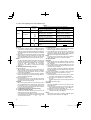
5. How to select tightening torque and rotational speed
Table 5
Use
Clutch Dial
Position
Rotating speed selection (Position of the shift knob)
LOW (Low speed) HIGH (High speed)
Driving
Machine screw 1 – 22
For 4 mm or smaller diameter
screws.
For 6 mm or smaller diameter
screws.
Wood screw
1 –
For 8 mm or smaller nominal
diameter screws. (DS18DFL)
For 4.8 mm or smaller nominal
diameter screws. (DS18DFL)
For 8 mm or smaller nominal
diameter screws. (DS14DFL)
For 3.8 mm or smaller nominal
diameter screws. (DS14DFL)
Drilling
Wood
For 38 mm or smaller diameters.
(DS18DFL)
For 24 mm or smaller diameters.
(DS18DFL)
For 30 mm or smaller diameters.
(DS14DFL)
For 12 mm or smaller diameters.
(DS14DFL)
Metal
For drilling with a metal working
drill bit.

19
(3) Using the bit holder (Hook with bit holder)
○ Installing the bit
Slide the bit from the side and then insert fi rmly until
the groove on the bit locks in the protruded section of
the hook.
○ Removing the bit
Securely hold the main unit and pull out the bit
by
holding the tip with your thumb (Fig. 14).
CAUTION
Only Hitachi STANDARD ACCESSORIES phillips bit
(No. 2 × 65L; Code No. 983006) may be used. Do not
use other bits since they may come loose.
11. Using the bit holder
CAUTION
○ Stow the bit in the specifi ed location on
the tool. If the tool
is used with the bit stowed improperly, the bit may fall and
cause bodily injury.
○ Do not stow bits that are of a diff erent length, gauge or
dimension than the plus driver bit (65 mm long) included
in the STANDARD ACCESSORIES. The bit
may fall and
cause bodily injury.
(1) Removing the bit
Securely hold the main unit and pull out the bit by holding
the tip with your thumb (Fig. 15).
(2) Installing the Bit
Install the bit with steps opposite of when removing.
Insert the bit so that the right and
left sides are equal, as
shown in Fig. 16.
MAINTENANCE AND INSPECTION
1. Inspecting the tool
Since use of as dull tool will degrade effi ciency and cause
possible motor malfunction, sharpen or replace the tool
as soon as abrasion is noted.
2. Inspecting the mounting screws
Regularly inspect all mounting screws and ensure that
they are properly tightened. Should any of
the screws be
loose, retighten them immediately. Failure to do so could
result in serious hazard.
3. Maintenance of the motor
The motor unit winding is the very “heart” of the power
tool. Exercise due care to ensure the winding does not
become damaged and/or wet with oil or water.
4.
Cleaning on the outside
When the driver drill is stained, wipe with a soft dry cloth
or a cloth moistened with soapy water. Do not use chloric
solvents, gasoline or paint thinner, for they melt plastics.
5. Storage
Store the driver drill in a place in which the temperature is
less than 40°C and out of reach of children.
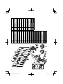
6. Service parts list
CAUTION:
Repair, modifi cation and inspection of Hitachi Power
Tools must be carried out by a Hitachi Authorized Service
Center.
This Parts List will be helpful if presented with the tool to
the Hitachi Authorized Service Center when
requesting
repair or other maintenance.
In the operation and maintenance of power tools, the
safety regulations and standards prescribed in each
country must be observed.
MODIFICATIONS:
Hitachi Power Tools are constantly being improved
and modifi ed to incorporate the latest technological
advancements.
Accordingly, some parts may be changed without prior
notice.
Important notice on the batteries for the Hitachi
cordless power tools
Please always use one of our designated genuine batteries.
We cannot guarantee the safety and performance of
our cordless power tool when used with batteries other
than these designated by us, or when the battery is
disassembled and modifi ed
(such as disassembly and
replacement of cells or other internal parts).
NOTE
Due to HITACHI’s continuing program of research and
development, the specifi cations herein are subject to
change without prior notice.

20
Item
No.
Part Name
1
SPECIAL SCREW
(LEFT HAND) M6 × 23
2
DRILL CHUCK
(W/O CHUCK WRENCH)
3GEAR BOX ASS'Y
4CLUTCH DIAL
5CLICK SPRING
6NUT
7SPRING
8WASHER (A)
9FRONT CASE
10 STEEL BALL D5
11 R ING GEAR
12 PLANET GEAR (C) SET
13 WASHER (A)
14 REAR CASE
15 TAPPING SCREW D3 × 12
16 SHIFT ARM
17 SLIDE RING GEAR
18 PINION (C)
19 PLANET GEAR (B) SET
20 PINION (B)
21 PLANET GEAR
(A) SET
22 FIRST RING GEAR
23 WASHER (B)
24 MOTOR SPACER
25 MOTOR
26 SPACER: DS14DFL
27
TAPPING SCREW
(W/FLANGE) D3 × 16
28 NAME PLATE
29 MACHINE SCREW M 4 × 6
30 HOUSING (A). (B) SET
Item
No.
Part Name
31
INTERNAL WIRE (B)
90L (BLACK)
32
INTERNAL WIRE (B)
140L (RED)
33 DC-SPEED CONTROL SWITCH
34 PUSHING BUTTON
35 FERRITE CORE
36 SHIFT KNOB
37 HITACHI LABEL
38 HOOK ASS'Y
39 V-LOCK NUT M5
40 STRAP
41 TERMINAL SUPPORT (A)
42 HOOK SPRING
43 SPECIAL SCREW M5
44-1
BATTERY
(BCL1415): DS14DFL
44-2
BATTERY
(BCL1815): DS18DFL
501 CHARGER (UC18YGL2)
502 + DRIVER BIT
503 CASE
ページが読み込まれています...
ページが読み込まれています...
ページが読み込まれています...
ページが読み込まれています...
-
 1
1
-
 2
2
-
 3
3
-
 4
4
-
 5
5
-
 6
6
-
 7
7
-
 8
8
-
 9
9
-
 10
10
-
 11
11
-
 12
12
-
 13
13
-
 14
14
-
 15
15
-
 16
16
-
 17
17
-
 18
18
-
 19
19
-
 20
20
-
 21
21
-
 22
22
-
 23
23
-
 24
24


Hikoki DS 14DFL ユーザーマニュアル
- カテゴリー
- パワーツール
- タイプ
- ユーザーマニュアル
他の言語で
- English: Hikoki DS 14DFL User manual
関連論文
その他のドキュメント
-
Roland R-09 取扱説明書
-
Hitachi DS 10DFL Handing Instructions
-
Hitachi DV18DSFL Handling Instructions Manual
-
-
-
DeWalt DCD780C2R ユーザーマニュアル
-
-
-
 Pro's Kit PT-1206 ユーザーマニュアル
-
 Z-Works DN3G6JA062 ユーザーマニュアル

