KYOCERA 5861 Series ユーザーマニュアル

タイプ
ユーザーマニュアル
106-03-003 🄫 2020 KYOCERA Corporation
No.
:
205-03-300
取扱説明書
INSTRUCTION MANUAL
5861
Series
0.35mm Pitch Board-to-Board Connector
D DCN20371 2020/04/07 K. Azuma H. Watanabe A. Tsunemura
C DCN-643 2017/06/29 K. Shiobara K. Yamane
O EDN-506 2015/10/27 K. Hirata K. Yamane
NO EDN/DCN DATE PREPARED by CHECKED by APPROVED by
Downloaded from Arrow.com.
5861 SERIES INSTRUCTION MANUAL No. 205-03-300
106-03-004 🄫 2020 KYOCERA Corporation PAGE 1/13
目次
TABLE OF CONTENTS
1. 概要 OUTLINE ········································································· 2
2. 部品名称および型番 PART NAMES AND MODEL NUMBERS ································· 2
2-1. 部品名称 PART NAMES ····························································· 2
2-2. 型番 MODEL NUMBERS ···························································· 3
3. 取り扱い上の注意 PRECAUTIONS IN HANDLING ··········································· 4
3-1. 基板対基板嵌合での使用に関して USING FOR BOARD-TO-BOARD CONNECTION ·········· 4
3-2. 基板対FPC嵌合での使用に関して USING FOR BOARD-TO-FPC CONNECTION ············· 5
3-3. 実装に関して MOUNTING ··························································· 6
3-4. 嵌合に関して ENGAGEMENT ························································· 8
3-5. チェッカーに関して CHECKER ························································· 9
3-6. 活線挿抜関して HOT SWAP ··························································· 9
3-7. プリント基板およびメタルマスク開口部推奨寸法に関して
PCB AND RECOMMENDED DIMENSIONS OF THE OPENING AREA IN THE METAL MASK ·· 10
3-8. 推奨吸着ノズル寸法に関して
RECOMMENDED DIMENSIONS OF THE PICK-UP NOZZLE ······························ 13
Downloaded from Arrow.com.Downloaded from Arrow.com.
5861 SERIES INSTRUCTION MANUAL No. 205-03-300
106-03-004 🄫 2020 KYOCERA Corporation PAGE 2/13
1. 概要 OUTLINE
本製品 5861 シリーズコネクタは、市場における高度実装化に対応すべく開発された、0.35mm ピッチの
ボードツーボードコネクタです。
Series 5861 connector is a board-to-board connector with 0.35mm pitch designed to miniaturize outer
dimension for high-density mounting.
2. 部品名称および型番 PART NAMES AND MODEL NUMBERS
2-1. 部品名称 PART NAMES
(1) プラグ Plug
(2) リセプタクル Receptacle
コンタクト
Contact
インシュレータ
Insulator
インシュレータ
Insulator
コンタクト
Contact
コンタクト
Contact
アンカープレート
Anchor Plate
アンカープレート
Anchor Plate
Downloaded from Arrow.com.Downloaded from Arrow.com.Downloaded from Arrow.com.
5861 SERIES INSTRUCTION MANUAL No. 205-03-300
106-03-004 🄫 2020 KYOCERA Corporation PAGE 3/13
2-2. 型番 MODEL NUMBERS
(1) プラグ Plug
Plug : 14 5861 XXX 024 829 +
14 : Plug
シリーズ番号 Series Number
極数 Number of Pos.
バリエーション Variation
めっきコード Plating Code
鉛フリー Lead Free
(2) リセプタクル Receptacle
Rec. : 24 5861 XXX 004 829 +
24 : Rec.
シリーズ番号 Series Number
極数 Number of Pos.
バリエーション Variation
めっきコード Plating Code
鉛フリー Lead Free
Downloaded from Arrow.com.Downloaded from Arrow.com.Downloaded from Arrow.com.Downloaded from Arrow.com.
5861 SERIES INSTRUCTION MANUAL No. 205-03-300
106-03-004 🄫 2020 KYOCERA Corporation PAGE 4/13
3. 取り扱い上の注意 PRECAUTIONS IN HANDLING
3-1. 基板対基板嵌合での使用に関して USING FOR BOARD-TO-BOARD CONNECTION
(1) 基板同士をネジ止めして固定する際は、コターをねじらないうにご注意下さ 基板や
ネジ穴のバラつきにより、コネクターがねじられた状で固される恐れがあります。
When the printed circuit boards on which connectors are mounted were fixed by using screw,
the mated connector could be twisted due to variations in dimensions of such as screw holes.
So great attention should be given not to twist connectors when fixing the boards.
(2) ネクターが基板に対してセンターに実装さない場合、もしく大きい基板同士の嵌合の場合に
嵌合が傾く恐れがありまので、下図のよう傾き防止用のスペーおよび嵌合方向への押さ
よる固定をお勧めします
When connectors are mounted off-center of the printed circuit board, or when the printed circuit
boards to be connected are rather large, mating may tilt. In order to avoid tilting, it is recommended
that the printed circuit boards are fixed by the spacer and something that generates a force to retain
the proper mated condition.
押さえ
Retaining Force
スペーサー
Spacer
基板
PCB
ネジ
Screw
Downloaded from Arrow.com.Downloaded from Arrow.com.Downloaded from Arrow.com.Downloaded from Arrow.com.Downloaded from Arrow.com.
5861 SERIES INSTRUCTION MANUAL No. 205-03-300
106-03-004 🄫 2020 KYOCERA Corporation PAGE 5/13
3-2. 基板対FPC嵌合での使用に関して USING FOR BOARD-TO-FPC CONNECTION
(1)コネクタを挿抜する際、製品に直接負荷がかからないように FPC の裏面に補強板を貼りつけた状
態での使用をお願い致します。
補強板仕様に関しましては弊社製品外形より大きいものを使用し、板厚については実践による確
認をお願い致します。
尚、弊社での確認結果から FPC+補強板の厚みは 0.3mm 以上を推奨致します。
(弊社条件は FPC:0.1mm 熱接着層:0.05mm +SUS 補強板 0.15 にて実施)
Please make sure to attach reinforcing board to FPC’s backso that it will relieve the product from the stress
caused by connector insertion /extraction
Such reinforcing board should be bigger than our productand its suitable thickness should be decided through
actual test
In addition, the thickness of FPC+reinforcing board recommends 0.3mm or more from our check result. (Our
condition is FPC:0.1mm + heat adhesive line:0.05mm + SUS Supporting Tape 0.15mm)
(2) 落下・衝撃や FPC 取り回しの際の反力が大きく加わることが懸念される場合はコネクタの嵌合方へ
の押さえによる固定をお勧め致します。
When such possibility as the product may fallreceive any impact or reaction force from being thrashed is
expectedand then it is recommended to fix them in the direction of engagement
コネクタ
pattern supporting
connector
Downloaded from Arrow.com.Downloaded from Arrow.com.Downloaded from Arrow.com.Downloaded from Arrow.com.Downloaded from Arrow.com.Downloaded from Arrow.com.
5861 SERIES INSTRUCTION MANUAL No. 205-03-300
106-03-004 🄫 2020 KYOCERA Corporation PAGE 6/13
3-3. 実装に関して MOUNTING
(1) 実装の際には接触部及びテール部に不要な外力が加わり変形等が生じないよう、ご注意お願い致します。
Please make sure that the product is free from deformity caused by the unnecessary stress to the contacting
points and the tail
(2) 自動実装の際には弊社推奨パターン図でのクリームはんだ印刷及び実装をお願い致します。
When the connectors are automatically mountedplease apply cream soldering printing in the process in
accordance with the pattern chart of our recommendation
(3) 外線リフローによるはんだ付けは下記に示す弊社推奨リフロー温度プロファイル条件での実施をお願い致
します。
※温度はコネクタ表面で測定した値とします。
For the soldering through infrared reflowplease apply our recommended temperature and profile condition
as the chart below(Solder : Sn-3.0Ag-0.5Cu)
※The temperature should be measured on the surface of connector
(4) N2リフローによるはんだ付けは、O2濃度が 1000ppm 程度で下記に示す弊社リフロー温度プロファイル条件
での実施を推奨致します。なお、リフローは 2 回以下を推奨します。
For the soldering through N2 reflowplease apply our recommended temperature and profile condition as the
chart below under the condition of 1000 ppm of O2 levelAnd, the reflow recommend 2 times or less.
(Solder : Sn-3.0Ag-0.5Cu)
(5) 実装条件が弊社推奨リフロー温度プロファイル条件と異なる場合はあらかじめ実装後にコネクタの変形、
変色が無いことをご確認の上、実装を行ってください。
When the mounting condition differs from those of our profile in any wayplease make sure that you do not
observe any deformity nor color change with the mounted connector beforehand
250
230
180
150
TEMP ON THE PARTS(℃)
PEAK
PRE HEAT
TIME(s)
90±30 s
30±10 s
TIME(s)
250
230
180
150
TEMP ON THE PARTS(℃)
PEAK
PRE HEAT
30±10s
90±30 s
Downloaded from Arrow.com.Downloaded from Arrow.com.Downloaded from Arrow.com.Downloaded from Arrow.com.Downloaded from Arrow.com.Downloaded from Arrow.com.Downloaded from Arrow.com.
5861 SERIES INSTRUCTION MANUAL No. 205-03-300
106-03-004 🄫 2020 KYOCERA Corporation PAGE 7/13
(6) 手付けはんだの際にはテール部及び基板へのフラックス塗布はしないで下さい。コネクタ内部及び接触部
へのフラックス上がり及び飛散の原因となり接触不良等の不具合が発生する場合があります。
又、はんだごてで端子に負荷をかけてはんだ付けを行うとテール部変形 及びインシュレータの溶け等の
恐れがありますのでご注意お願い致します。
Please do not apply flux onto the tail and PC boardwhen it is soldered manuallySplattered or migrated
flux inside the connector or to the contact points may cause imperfect contact
Also avoid giving any stress to the product with the soldering ironIt could deform tail or melt insulator
(7) PLUG 側は接点が外側に露出している為、実装の際はフラックスの飛散に ご注意お願い致します。
Since the contacting areas of the plug connector are exposed to the outer side, pay attention that the areas
would not be splashed with flux in the soldering process.
(8) 実装後、酸化の影響ではんだ付け部に変色が見られる事がありますが、製品性能に影響はありません。
There is no influence in the product performance thought discoloration might be seen in
the soldering tail after mounting.
(9) 実装後、テール上面にはんだ濡れ広がりのない場合がありますが、製品性能に影響はありません。
There is no influence in the product performance though the tail surface doesn't get wet with solder after
mounting.
Contact area
はんだごて
soldering iron
Downloaded from Arrow.com.Downloaded from Arrow.com.Downloaded from Arrow.com.Downloaded from Arrow.com.Downloaded from Arrow.com.Downloaded from Arrow.com.Downloaded from Arrow.com.Downloaded from Arrow.com.
5861 SERIES INSTRUCTION MANUAL No. 205-03-300
106-03-004 🄫 2020 KYOCERA Corporation PAGE 8/13
3-4. 嵌合に関して ENGAGEMENT
(1) コネクタの接触部に触れたり、異物を入れるとバネの変形等の原因となりますのでご注意お願い致します。
If something touches the contact points or with some foreign objectthe spring could be deformed
(2) 本製品は小型、軽量化をする為に成形品の肉厚を薄くしており、嵌合・離脱時に過度なねじり挿抜は成形
品の破壊、端子の変形、テール部はんだ剥離の原因となりますので注意お願い致します。
We minimized the thickness of this product to achieve downsizing and light weightinessBecause of this
distorted attachment at engagement /disengagement could cause destructionterminal deformityplating
detachment on the tail
こじり
Uneven Pressure
ねじり
Distorted Attachment
万が一こじり抜去を行う必要がる場合は、長手方向に行って下さい但し、長手方向への作業は、
じる側の実装基板・FPC 厚みにコネクタが山反り方向に変形、または、破損す場合が
ります。事前にご確認の上、作業を行って下さい。
If it is required to unmate connectors with uneven pressure, apply such pressure to the long side of the
connector. Applying the uneven pressure to the long side of the connector may cause doomed warpage or
destruction on the connector depending on the PCB/FPC thickness. Please make sure beforehand when you
apply the uneven pressure to the long side of the connector.
×
uneven pressure distorted attachment
基板
FPC
Downloaded from Arrow.com.Downloaded from Arrow.com.Downloaded from Arrow.com.Downloaded from Arrow.com.Downloaded from Arrow.com.Downloaded from Arrow.com.Downloaded from Arrow.com.Downloaded from Arrow.com.Downloaded from Arrow.com.
5861 SERIES INSTRUCTION MANUAL No. 205-03-300
106-03-004 🄫 2020 KYOCERA Corporation PAGE 9/13
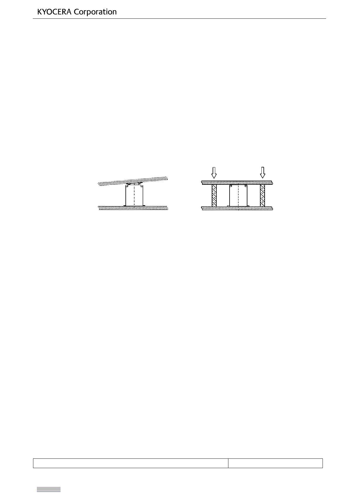
(3) 嵌合は位置合わせを行った上で、Plug 側、Rec.側の両方が平行になる状態で行って下さい。
なお、嵌合位置合わせは、過度な力を加えずに行って下さい。過度な力を加えた場合、成形品の破壊等、
発生する場合があります。
Align connectors before mating, and apply pressure on plug and receptacle connectors so that they would be
mated straight in parallel. Do not apply an excessive pressure when aligning them, or mold goods could be
damaged or broken.
(4) 製品幅が小さいため、嵌合位置合わせは Plug、Rec.が大きくズレないように、ご注意をお願い致します。
Because the connector is very small, be careful not to move the plug or receptacle connector when aligning
them.
(5) 本製品はコネクタのみでの基板保持は出来ません。押さえが無い場合、嵌合のはずれ、
テールはんだ剥離、接触不安定が懸念されます。スペーサーなどをご使用頂き、ねじ止めなどの
嵌合固定が必要です。
The connector is impossible to support the PCB by itself. Without other supporting objects,
imperfect mating , peeling of tails or contacting failure may be caused. As supporting objects,
use spacers fixed by screws.
3-5. チェッカーに関して CHECKER
本製品をそのままチェッカーとしてご使用する場合、耐久性が劣ること、相手側製品に過度にダメージを与え
る場合がありますので、ご注意願います。チェッカーをご要望の際は弊社までご連絡願います。
If the connector targeted in this manual is used as a checker, please be informed that durability
may not be high enough or the product to be checked could be damaged excessively.
Please contact us when you request
our specified
plug or receptacle for the checker.
3-6. 活線挿抜関して HOT SWAP
本製品に電流を流した状態での挿抜は、なさらないよう御願い致します。
Insertion and separation under live current shall not be done.
NG OK
Downloaded from Arrow.com.Downloaded from Arrow.com.Downloaded from Arrow.com.Downloaded from Arrow.com.Downloaded from Arrow.com.Downloaded from Arrow.com.Downloaded from Arrow.com.Downloaded from Arrow.com.Downloaded from Arrow.com.Downloaded from Arrow.com.
5861 SERIES INSTRUCTION MANUAL No. 205-03-300
106-03-004 🄫 2020 KYOCERA Corporation PAGE 10/13
3-7. プリント基板およびメタルマスク開口部推奨寸法に関して
PCB AND RECOMMENDED DIMENSIONS OF THE OPENING AREA IN THE METAL MASK
本コネクタは、ピッチ間隔が 0.35mm であり、高密度実装が要求されるコネクタとなっております。 高密度実装
が要求されるコネクタに関しては、半田ブリッジによるショート等の実装不具合を減らすために適正なはんだ量
の管理が必要となります。 つきましては、添付推奨寸法図をご参考願います。 (プリント基板寸法の詳細につ
きましては、弊社製品図面をご参照ください)
This series of connector is required to be mounted in the high density due to its 0.35mm pitches. The connectors
mounted in the high density need to be controlled adequate amount of solder in order to prevent failures in the
mounting process such as short-circuit caused by solder bridge. For the dimensions of the metal mask opening,
therefore, please refer to our recommended dimensions shown in the attached drawing. (For detailed dimensions of
the printed circuit board, please refer to our product drawings.)
As dimensions shown in the drawings are our recommendations. Please feel free to
contact us if you have any questions and
or concerns about these dimensions.
プリント基板およびメタルマスク開口部寸法は推奨ですので不明点や懸念点等がございましたらご
相談いただけますようお願いします。
Downloaded from Arrow.com.Downloaded from Arrow.com.Downloaded from Arrow.com.Downloaded from Arrow.com.Downloaded from Arrow.com.Downloaded from Arrow.com.Downloaded from Arrow.com.Downloaded from Arrow.com.Downloaded from Arrow.com.Downloaded from Arrow.com.Downloaded from Arrow.com.
5861 SERIES INSTRUCTION MANUAL No. 205-03-300
106-03-004 🄫 2020 KYOCERA Corporation PAGE 11/13
PLUG REC.
Pad
Stencil
t=0.12mm
Stencil
t=0.1mm
5
58
86
61
1
S
Se
er
ri
ie
es
s:
:
0
0.
.3
35
5
m
mm
m
P
Pi
it
tc
ch
h
Recommended Pad & Stencil size (SIGNAL CONTACT)
0.18mm
0.55mm
0.18mm
0.38mm
0.18mm
0.35mm
0.18mm
0.39mm
0.18mm
0.38mm
0.18mm
0.32mm
Downloaded from Arrow.com.Downloaded from Arrow.com.Downloaded from Arrow.com.Downloaded from Arrow.com.Downloaded from Arrow.com.Downloaded from Arrow.com.Downloaded from Arrow.com.Downloaded from Arrow.com.Downloaded from Arrow.com.Downloaded from Arrow.com.Downloaded from Arrow.com.Downloaded from Arrow.com.
5861 SERIES INSTRUCTION MANUAL No. 205-03-300
106-03-004 🄫 2020 KYOCERA Corporation PAGE 12/13
PLUG REC.(SPAN) REC.(PITCH)
Pad
Stencil
t=0.12mm
Stencil
t=0.1mm
REC. MOUNTING LAYOUT
5
58
86
61
1
S
Se
er
ri
ie
es
s
:
:
0
0.
.3
35
5
m
mm
m
P
Pi
it
tc
ch
h
Recommended Pad & Stencil size (ANCHOR PLATE)
PITCH
SIGNAL
0.3mm
1.0mm
0.4mm(15.8mil)
1.2mm
0.35mm
0.8m
0.8mm
0.4mm
0.3mm
0.2mm
0.25mm
0.34mm
0.35mm
0.2mm
0.21mm
0.28mm
0.315mm
0.18mm
0.35mm
0.35mm
0.8mm
0.3mm
0.35m
1.0mm
0.3mm
Downloaded from Arrow.com.Downloaded from Arrow.com.Downloaded from Arrow.com.Downloaded from Arrow.com.Downloaded from Arrow.com.Downloaded from Arrow.com.Downloaded from Arrow.com.Downloaded from Arrow.com.Downloaded from Arrow.com.Downloaded from Arrow.com.Downloaded from Arrow.com.Downloaded from Arrow.com.Downloaded from Arrow.com.
5861 SERIES INSTRUCTION MANUAL No. 205-03-300
106-03-004 🄫 2020 KYOCERA Corporation PAGE 13/13
3-8. 推奨吸着ノズル寸法に関して
RECOMMENDED DIMENSIONS OF THE PICK-UP NOZZLE
推奨吸着ノズル寸法は以下の通りです。
The following is the recommended dimensions of the pick-up nozzle.
コネクタが基板上に有る際の最大加圧荷重 20N
Maximum pressure when the connector is placed on a PCB: 20N
Downloaded from Arrow.com.Downloaded from Arrow.com.Downloaded from Arrow.com.Downloaded from Arrow.com.Downloaded from Arrow.com.Downloaded from Arrow.com.Downloaded from Arrow.com.Downloaded from Arrow.com.Downloaded from Arrow.com.Downloaded from Arrow.com.Downloaded from Arrow.com.Downloaded from Arrow.com.Downloaded from Arrow.com.Downloaded from Arrow.com.
  • Page 1 1
  • Page 2 2
  • Page 3 3
  • Page 4 4
  • Page 5 5
  • Page 6 6
  • Page 7 7
  • Page 8 8
  • Page 9 9
  • Page 10 10
  • Page 11 11
  • Page 12 12
  • Page 13 13
  • Page 14 14

KYOCERA 5861 Series ユーザーマニュアル

タイプ
ユーザーマニュアル

他の言語で