
Precision 7750
Service Manual
Regulatory Model: P44E
Regulatory Type: P44E001
May 2020
Rev. A00

注意、小心和警告
注: “注意”表示帮助您更好地使用该产品的重要信息。
小心: “小心”表示可能会损坏硬件或导致数据丢失,并告诉您如何避免此类问题。
警告: “警告”表示可能会导致财产损失、人身伤害甚至死亡。
© 2020 Dell Inc. 或其子公司。保留所有权利。Dell、EMC 和其他商标均是 Dell Inc. 或其子公司的商标。其他商标可能是其各自所有者
的商标。

1 拆装计算机内部组件....................................................................................................................... 6
安全说明.................................................................................................................................................................................6
拆装计算机内部组件之前..............................................................................................................................................6
安全防范措施...................................................................................................................................................................7
静电放电 — ESD 保护................................................................................................................................................... 7
ESD 现场服务套件.......................................................................................................................................................... 7
拆装计算机内部组件之后..............................................................................................................................................8
2 技术和组件................................................................................................................................... 9
USB 功能................................................................................................................................................................................ 9
USB Type-C..........................................................................................................................................................................10
HDMI 2.0............................................................................................................................................................................... 12
NVIDIA Quadro T1000......................................................................................................................................................... 12
NVIDIA Quadro RTX3000................................................................................................................................................... 13
NVIDIA Quadro RTX4000................................................................................................................................................... 13
NVIDIA Quadro RTX5000................................................................................................................................................... 14
3 拆卸和重新组装........................................................................................................................... 15
SD 卡..................................................................................................................................................................................... 15
卸下 SD 卡...................................................................................................................................................................... 15
安装 SD 卡...................................................................................................................................................................... 15
SSD 盖板...............................................................................................................................................................................15
Removing SSD door.......................................................................................................................................................15
Installing SSD door......................................................................................................................................................... 16
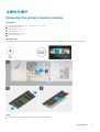
次要 M.2 固态硬盘.............................................................................................................................................................. 17
Removing the secondary M.2 Solid-state drive......................................................................................................... 17
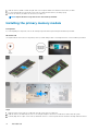
Installing the secondary M.2 SSD module...................................................................................................................18
基座护盖............................................................................................................................................................................... 19
Removing the base cover..............................................................................................................................................19
Installing the base cover............................................................................................................................................... 22
电池.......................................................................................................................................................................................24
锂离子电池预防措施....................................................................................................................................................24
Removing the battery................................................................................................................................................... 24
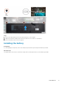
Installing the battery......................................................................................................................................................25
固态驱动器.......................................................................................................................................................................... 26
Removing the primary M.2 Solid-state drive............................................................................................................. 26
Installing the primary M.2 SSD module.......................................................................................................................28
次要内存模块...................................................................................................................................................................... 29
Removing the secondary memory module.................................................................................................................29
Installing the secondary memory module................................................................................................................... 30
SIM 卡...................................................................................................................................................................................30
Removing the SIM card................................................................................................................................................ 30
Installing the SIM card................................................................................................................................................... 31
WLAN 卡...............................................................................................................................................................................32
Contents
Contents 3

Removing the WLAN card............................................................................................................................................32
Installing the WLAN card.............................................................................................................................................. 33
WWAN 卡.............................................................................................................................................................................34
Removing the WWAN card.......................................................................................................................................... 34
Installing the WWAN card.............................................................................................................................................34
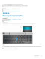
键盘格架.............................................................................................................................................................................. 35
Removing the keyboard lattice.................................................................................................................................... 35
Installing the keyboard lattice.......................................................................................................................................36
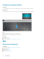
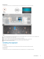
键盘.......................................................................................................................................................................................36
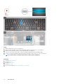
Removing the keyboard................................................................................................................................................36
Installing the keyboard...................................................................................................................................................37
主要内存模块...................................................................................................................................................................... 39
Removing the primary memory module......................................................................................................................39
Installing the primary memory module........................................................................................................................ 40
散热器................................................................................................................................................................................... 41
Removing the heat-sink assembly................................................................................................................................41
Installing the heat sink assembly..................................................................................................................................42
电源适配器端口.................................................................................................................................................................. 43
Removing the power-adapter port..............................................................................................................................43
Installing the power-adapter port................................................................................................................................43
电源按钮板.......................................................................................................................................................................... 44
Removing the power button board............................................................................................................................. 44
Installing the power button board............................................................................................................................... 45
带指纹读取器的电源按钮板............................................................................................................................................. 45
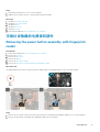
Removing the power button assembly with fingerprint reader...............................................................................45
Installing the power button assembly with fingerprint reader................................................................................. 46
内框架...................................................................................................................................................................................47
Removing the inner frame............................................................................................................................................ 47
Installing the inner frame.............................................................................................................................................. 48
智能卡固定框架..................................................................................................................................................................49
Removing the smart-card reader................................................................................................................................ 49
Installing the smart-card reader.................................................................................................................................. 50
触摸板按钮........................................................................................................................................................................... 51
Removing the Touchpad buttons.................................................................................................................................51
Installing the Touchpad buttons.................................................................................................................................. 52
SD 卡读卡器........................................................................................................................................................................ 53
Removing SD card reader............................................................................................................................................ 53
Installing SD card reader...............................................................................................................................................54
电源按钮.............................................................................................................................................................................. 55
Removing the power button........................................................................................................................................55
Installing the power button.......................................................................................................................................... 56
带指纹读取器的电源按钮部件......................................................................................................................................... 57
Removing the power button assembly with fingerprint reader............................................................................... 57
Installing the power button assembly with fingerprint reader................................................................................. 58
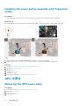
GPU 电源线......................................................................................................................................................................... 58
Removing the GPU power cable................................................................................................................................. 58
Installing the GPU power cable....................................................................................................................................59
系统板...................................................................................................................................................................................60
Removing the system board........................................................................................................................................ 60
Installing the system board...........................................................................................................................................63
4
Contents

GPU 卡................................................................................................................................................................................. 66
卸下 GPU 卡.................................................................................................................................................................. 66
安装 GPU 卡.................................................................................................................................................................. 66
扬声器...................................................................................................................................................................................67
Removing the speaker.................................................................................................................................................. 67
Installing the speaker.....................................................................................................................................................68
中盖.......................................................................................................................................................................................70
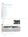
Removing the middle cap............................................................................................................................................. 70
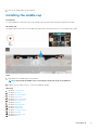
Installing the middle cap.................................................................................................................................................71
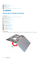
显示屏部件...........................................................................................................................................................................72
Removing the display assembly................................................................................................................................... 72
Installing the display assembly......................................................................................................................................74
掌垫....................................................................................................................................................................................... 77
Removing the palmrest................................................................................................................................................. 77
Installing the palmrest................................................................................................................................................... 78
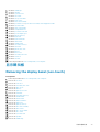
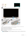
显示屏挡板.......................................................................................................................................................................... 79
Removing the display bezel (non-touch)....................................................................................................................79
Installing the display bezel (non-touch)......................................................................................................................80
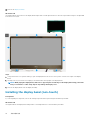
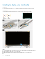
显示屏面板.......................................................................................................................................................................... 82
Removing the display panel (non-touch)................................................................................................................... 82
Installing the display panel (non-touch)......................................................................................................................84
显示屏铰接部件..................................................................................................................................................................85
Removing the display hinge..........................................................................................................................................85
Installing the display hinge (non-touch)......................................................................................................................86
摄像头...................................................................................................................................................................................88
Removing the camera (non-touch)............................................................................................................................ 88
Installing the camera..................................................................................................................................................... 89
P 传感器板...........................................................................................................................................................................90
卸下 P 传感器板........................................................................................................................................................... 90
安装 P 传感器板............................................................................................................................................................ 91
显示屏线缆........................................................................................................................................................................... 91
Removing the display cable...........................................................................................................................................91
Installing the display cable............................................................................................................................................ 93
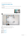
Display back cover...............................................................................................................................................................94
Replacing the display cable...........................................................................................................................................94
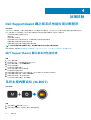
4 故障排除.................................................................................................................................... 96
Dell SupportAssist 启动前系统性能检查诊断程序........................................................................................................ 96
运行 SupportAssist 启动前系统性能检查.................................................................................................................96
系统主板内置自检 (M-BIST)............................................................................................................................................96
显示屏面板电源导轨内置自检 (L-BIST).........................................................................................................................97
显示屏面板内置自检 (LCD-BIST)....................................................................................................................................97
系统诊断指示灯..................................................................................................................................................................98
WiFi 重启.............................................................................................................................................................................. 99
5 获取帮助...................................................................................................................................100
联系戴尔.............................................................................................................................................................................100
Contents
5

拆装计算机内部组件
安全说明
前提条件
遵循以下安全原则可防止您的计算机受到潜在损坏并确保您的人身安全。除非另有说明,否则将假设在执行本文档所述的每个过程
时均满足以下条件:
• 已经阅读了计算机附带的安全信息。
• 以相反顺序执行拆卸步骤可以更换组件或安装单独购买的组件。
关于此任务
注: 先断开所有电源,然后再打开计算机盖或面板。执行完计算机组件拆装工作后,装回所有护盖、面板和螺钉后再连接电源。
警告: 拆装计算机内部组件之前,请阅读计算机附带的安全说明。有关其他安全妥善实践信息,请参阅 Regulatory Compliance
Homepage(管理合规性主页)
小心: 多数维修只能由经认证的维修技术人员进行。您只能根据产品说明文件中的授权,或者在联机或电话服务和支持团队的指
导下进行故障排除和简单维修。由于进行未被戴尔授权的维修所造成的损坏不在保修之内。请阅读并遵循产品附带的安全说明。
小心: 为防止静电放电,请使用接地腕带或不时触摸未上漆的金属表面(例如计算机背面的连接器)以导去身上的静电。
小心: 组件和插卡要轻拿轻放。请勿触摸组件或插卡上的触点。持拿插卡时,应持拿插卡的边缘或其金属固定支架。持拿处理器
等组件时,请持拿其边缘,而不要持拿插针。
小心: 断开线缆连接时,请握住其插头或拉环,请勿直接握住线缆。某些线缆的连接器带有锁定卡舌;如果要断开此类线缆的连
接,请先向内按压锁定卡舌,然后再将线缆拔出。在拔出连接器的过程中,请保持两边对齐以避免弄弯任何连接器插针。另外,
在连接线缆之前,请确保两个连接器均已正确定向并对齐。
注: 您的计算机及特定组件的颜色可能与本说明文件中所示颜色有所不同。
拆装计算机内部组件之前
关于此任务
为避免损坏计算机,请在开始拆装计算机内部组件之前执行以下步骤。
步骤
1. 确保遵循安全说明。
2. 确保工作表面平整、整洁,以防止刮伤主机盖。
3. 关闭计算机。
4. 断开计算机上所有网络电缆的连接。
小心: 要断开网络电缆的连接,请先从计算机上拔下网络电缆,再将其从网络设备上拔下。
5. 断开计算机和所有连接的设备与各自电源插座的连接。
6. 计算机未插电时,按住电源按钮以导去系统板上的静电。
注: 为防止静电放电,请使用接地腕带或不时触摸未上漆的金属表面(例如计算机背面的连接器)以导去身上的静电。
1
6 拆装计算机内部组件

安全防范措施
安全预防措施一章详细介绍了在执行任何拆卸说明之前应采取的主要步骤。
在执行任何涉及拆卸或重新组装的安装或中断/修复过程之前,请遵守以下安全预防措施:
• 关闭系统和所有连接的外围设备。
• 断开系统和所有已连接的外围设备与交流电源的连接。
• 断开所有网络线缆、电话和电信线路与系统的连接。
• 拆装任何平板电脑笔记本系统内部组件时,请使用 ESD 现场服务套件,以避免静电放电 (ESD) 损坏。
• 卸下系统组件后,小心地将卸下的组件放在防静电垫上。
• 穿戴具有绝缘橡胶鞋底的鞋子以减少产生静电的机会。
备用电源
带有备用电源的戴尔产品必须完全断电,然后才能打开包装。包含备用电源的系统在关闭时实际上会开机。内部电源使系统能够远
程开启(LAN 唤醒)和暂挂进入休眠模式,并且具有其他高级电源管理功能。
拔下电源并按住电源按钮 15 秒应释放系统板中的剩余电量。从平板电脑卸下电池。笔记本卸下电池。
接合
接合是将两个或多个接地导体连接至同一个电源的一种方法。该操作可以通过使用现场服务静电放电 (ESD) 套件完成。连接接合线
时,请确保已将其连接至裸机,切勿接触漆面或非金属表面。腕带应固定并与您的皮肤全面接触,请确保脱下手表、手镯或戒指等
所有饰品,您才能与设备接合。
静电放电 — ESD 保护
处理电子组件,特别是敏感组件,如扩展卡、处理器、内存 DIMM 和系统主板时,ESD 是主要问题。即使轻微的放电也可能对电路
造成的损害,可能不明显,例如间歇性问题或产品寿命缩短。随着行业发展迫切要求降低功耗需求和提高密度,ESD 保护越来越重
要。
由于最近的戴尔产品中的半导体使用密度增大,现在,对静电损坏的敏感度比以前的戴尔产品中更高。因此,以前经过批准的一些
处理部件的方法不再适用。
两种已识别的 ESD 损坏类型为严重和间歇性故障。
• 严重 – 严重故障在 ESD 相关故障中约占 20%。该损坏可导致立即且完全失去设备功能。严重故障的示例如内存 DIMM 受到静电
电击,立即产生“无法开机自检/无视频”症状,并发出报警音提示内存缺失或内存无效。
• 间歇性 – 间歇性故障约占 ESD 相关故障的 80%。高频率的间歇性故障意味着在发生损坏的大多数时间里,故障无法立即被识
别。DIMM 受到静电电击,但线路只是弱化,而没有立即出现与损坏相关的明显症状。弱化线路问题可能需要数周或数月才能消
失,在此期间可能导致内存完整性降级、间歇性内存错误等。
更难识别和诊断的损坏类型为间歇性(也称为潜在或“带病运行”)故障。
执行以下步骤可避免 ESD 损坏:
• 使用正确接地的 ESD 腕带。不再允许使用无线防静电腕带;它们无法提供充分的保护。随着对 ESD 损坏的敏感度增强,处理部
件之前接触机箱不能确保对部件提供足够的 ESD 保护。
• 在静电安全的区域处理所有的静电敏感组件。如果可能,使用防静电的地板垫和工作台垫。
• 在打开对静电敏感的组件的运输纸板箱时,要在准备安装此组件时再将其从防静电包装材料中取下。打开防静电包装之前,请务
必确保释放身体静电。
• 在运输对静电敏感的组件前,将它置于防静电的容器或包装内。
ESD 现场服务套件
无监控的现场服务套件是最常使用的服务套件。每个现场服务套件包括三个主要部件:防静电垫子、腕带和联结线。
ESD 现场服务套件的组件
ESD 现场服务套件包含以下组件:
• 防静电垫子 – 防静电垫子可耗散电量,在维修过程中可用来放置部件。使用防静电垫子时,应正确佩戴腕带,并应使用联结线将
垫子连接到正在处理的系统上的裸金属。正确部署后,可以从 ESD 包中取出维修部件,然后直接放在垫子上。放置 ESD 敏感部
件的安全地方是您的手中、ESD 垫子上、系统中或包内。
拆装
计算机内部组件 7

• 腕带和联结线 – 腕带和联结线可以直接连接您的手腕和硬件上的裸金属(如果不需要 ESD 垫子),或连接到防静电垫子以保护
临时放置在垫子上的硬件。您的皮肤、ESD 垫子以及硬件之间的腕带和联结线的物理连接被称为联结。只能将现场服务套件与腕
带、垫子和联结线配合使用。切勿使用无线腕带。请始终注意,正常佩戴和磨损也很容易损坏腕带的内部电线,必须使用腕带测
试仪定期检查腕带,以避免意外的 ESD 硬件损坏。建议至少一星期检查一次腕带和联结线。
• ESD 腕带测试仪 – ESD 腕带内部的电线容易随着时间推移而损坏。使用无监控的套件时,最好在每次服务呼叫之前定期测试腕
带,最少每周一次。腕带测试仪是执行此测试的最佳方法。如果您自己没有腕带测试仪,请联系您的地区办公室,看他们是否
有。要执行测试,在将腕带连接到您的手腕后,将腕带联结线插入测试仪器,然后按按钮以进行测试。如果测试成功,将亮起绿
色指示灯,如果测试失败,则亮起红色指示灯并发出报警音。
• 绝缘元件 – 请务必保持塑料散热器外壳等 ESD 敏感设备远离作为绝缘体并且通常带有大量电荷的内部部件。
• 工作环境 – 在部署 ESD 现场服务套件之前,评估客户位置的情况。例如,为服务器环境部署套件与为台式机或笔记本电脑环境
部署有所差异。服务器通常安装在数据中心内的机架中,台式机或笔记本电脑通常放置在办公桌或小隔间。始终寻找宽敞的平坦
工作区,不杂乱且空间足以使用 ESD 套件,有额外的空间来容纳要维修的系统类型。工作空间还应没有绝缘体,以免引起 ESD
事件。在工作区域中实际处理任何硬件组件之前,必须将泡沫和其它塑料之类的绝缘体与敏感部件始终保持 30 厘米(12 英寸)
以上的距离。
• ESD 包装 – 所有对 ESD 敏感的设备必须使用防静电包装进行发送和接收。金属静电屏蔽袋将是首选。而且,您应始终应使用新
部件抵达时的相同 ESD 袋和包装来退回受损部件。ESD 袋应折叠并封嘴,同时应使用新部件抵达时原始包装盒中使用的相同泡
沫包装材料。请仅在 ESD 书保护的工作空间中取出 ESD 敏感型设备,并且部件不得放到 ESD 袋上,因为只有袋子内部是防静电
的。始终将部件放在您的手中、ESD 垫子上、系统中或者防静电袋中。
• 运输敏感组件 – 运输 ESD 敏感组件(例如备用部件或要返回给戴尔的部件)时,务必将这些部件放在防静电袋中以进行安全运
输。
ESD 保护总结
在任何时候维修戴尔产品时,建议所有现场服务技术人员使用传统有线 ESD 接地腕带和保护性防静电垫子。此外,执行维修时,技
术人员须将敏感部件与所有绝缘部件分开,并且必须使用防静电袋来运送敏感组件。
拆装计算机内部组件之后
关于此任务
完成所有更换步骤后,请确保在打开计算机前已连接好所有外部设备、插卡和线缆。
步骤
1. 将电话线或网线连接到计算机。
小心: 要连接网线,请先将线缆插入网络设备,然后将其插入计算机。
2. 将计算机和所有已连接设备连接至电源插座。
3. 打开计算机电源。
4. 如果需要,运行 SupportAssist 诊断程序 以验证计算机是否正常工作。
8
拆装计算机内部组件

技术和组件
本章详细介绍系统中提供的技术和组件。
主题:
• USB 功能
• USB Type-C
• HDMI 2.0
• NVIDIA Quadro T1000
• NVIDIA Quadro RTX3000
• NVIDIA Quadro RTX4000
• NVIDIA Quadro RTX5000
USB 功能
通用串行总线 (USB) 于 1996 年推出。它大幅简化了主机计算机和外围设备(例如,鼠标、键盘、外部驱动程序和打印机)之间的连
接。
表
. 1: USB 的演变
类型 数据传输速率 类别 推出年份
USB 2.0 480 Mbps 高速 2000
USB 3.2 第 1 代(之前
USB 3.0/USB 3.1 第 1
代)
5 Gbps 超高速 2010
USB 3.1 第 2 代 10 Gbps 超极速 2013
USB 3.2 第 1 代(超高速 USB)
多年来,USB 2.0 一直稳定地作为个人计算机界的实际接口标准,相关设备已售出 60 亿台,而且在空前快速的计算硬件和空前巨大
的带宽需求下,其需要更大的速度提升。USB 3.0/USB 3.1 Gen 1 凭借理论上比其前代产品快 10 倍的速度,最终满足了消费者的需
求。简而言之,USB 3.2 第 1 代功能如下所示:
• 更高的传输速率(最高 20 Gbps)。
• 增加了每 10 Gbps 的多通道操作。
• 增加了最大总线功率以及增加了设备电流引出,更好地适应耗电设备。
• 新的电源管理功能。
• 全双工数据传输和新传输类型支持。
• 与 USB 3.1/3.0 和 USB 2.0 的向后兼容性。
• 新的连接器和线缆。
下述主题介绍了有关 USB 3.0/USB 3.2 第 1 代的一些最常见问题。
速度
当前,最新的 USB 3.0/USB 3.1 第 1 代规范定义了 5 种速度模式。根据 USB 数据传输,它们被分类为低速、全速、高速(从 2.0 版
规格开始)、超高速(从 3.0 版开始)和超极速(从 3.1 版开始)。新的超极速模式的传输率为 20 Gbps。USB 3.2 标准向后兼容
USB 3.1/3.0 和 USB 2.0。
2
技术和组件 9

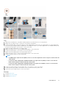
USB 3.2 第 1 代通过下述技术变革实现了更高的性能:
• 与现有 USB 2.0 总线并行添加的附加物理总线(参见下图)。
• USB 2.0 以前有四根电线(电源线、接地线和一对用于差分数据的线路);USB 3.1 第 1 代又增加了四根电线用作两对差分信号线
(接收和发送),总计八个连接器和接线。
• USB 3.2 第 1 代利用双向数据接口,而不是 USB 2.0 的半双工排列。这使理论带宽增加了 10 倍。
应用程序
USB 3.1 第 1 代提高了速度,使设备能够提供更好的整体体验。以前,几乎无法支持 USB 视频(从最大分辨率、延迟和视频压缩的角
度来看都是如此),不难想象到,将带宽增加 5-10 倍后,USB 视频解决方案的性能会显著提升。单链路 DVI 需要将近 2 Gbps 吞吐
量。当限制为 480 Mbps 时,5 Gbps 更具前景。通过承诺的 4.8 Gbps 速度,之前未进入 USB 范围的某些产品(例如,外部 RAID 存
储系统)将采用此标准。
下面列出了部分可用的超高速 USB 3.0/USB 3.1 Gen 1 产品:
• 外部台式机 USB 3.0/USB 3.2 第 1 代硬盘
• 便携式 USB 3.2 第 1 代硬盘
• USB 3.2 第 1 代驱动器坞站和适配器
• USB 3.2 第 1 代闪存盘和读取器
• USB 3.2 第 1 代固态硬盘
• USB 3.2 第 1 代 RAID
• 光介质驱动器
• 多媒体驱动器
• 网络
• USB 3.2 第 1 代适配器卡和集线器
兼容性
好消息是,USB 3.2 第 1 代从一开始就经过仔细规划,以与 USB 2.0 共存。首先,尽管 USB 3.2 第 1 代指定了新的物理连接,而且新
的线缆可充分利用新协议的更高速度能力,但连接器本身保持矩形形状不变,在与以前完全相同的位置具有四个 USB 2.0 触点。5 个
新连接可独立传输接收和发送的数据,它们位于 USB 3.0/USB 3.2 第 1 代线缆上,仅当连接到正确的超高速 USB 连接时,才会接触
到位。
USB Type-C
USB Type-C 是全新的小型物理连接器。该连接器本身可支持各种新的 USB 标准,如 USB 3.1 和 USB Power Delivery (USB PD)。
替代模式
USB Type-C 是新的小型连接器标准。它大约是旧的 USB Type-A 插头的三分之一。这是单一连接器标准,每个设备都能够使用。
USB Type-C 端口使用“备选模式”支持各种不同的协议,允许您的适配器从一个 USB 端口输出 HDMI、VGA、DisplayPort 或其他连接
类型
USB 供电
USB PD 规格还与 USB Type-C 密切相关。当前,智能手机、平板电脑和其他移动设备通常使用 USB 连接进行充电。USB 2.0 连接可
以提供最高 2.5 W 电源 — 这仅仅可以为您的手机充电。例如,笔记本电脑可能需要最高 60 W。USB 供电规格将此电源交付能力提
升到最高 100 W。它是双向的,设备可以发送或接收电力。并且此电力在设备跨连接传输数据的同时进行传输。
这预示着可以抛却一切专属笔记本电脑充电缆线,只通过标准 USB 连接即可为任何设备充电。从今天开始,您可以使用为智能手机
和其他便携式设备充电的便携式电池包为您的笔记本电脑充电。您可以将笔记本电脑插入连接到电源缆线的外部显示屏,该外部显
示屏将为您的笔记本电脑充电 — 只需使用一个小型 USB Type-C 接口。要使用此方法,设备和线缆必须支持 USB 供电。仅仅具有
USB Type-C 接口并不意味着它们可以执行这些操作。
10
技术和组件

USB Type-C 和 USB 3.2
USB 3.2 是新的 USB 标准。USB 3 的理论带宽是 5 Gbps,而 USB 3.2 是 20 Gbps,即第一代 Thunderbolt 连接器两倍的带宽。USB
Type-C 与 USB 3.2 不同。USB Type-C 仅仅是接口类型,其基础即使可能仅仅是 USB 2 或 USB 3.0。实际上,Nokia 的 N1 Android 平
板电脑使用 USB Type-C 连接器,但其基础技术是 USB 2.0 — 甚至不是 USB 3.0。不过,这些技术紧密相关。
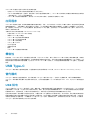
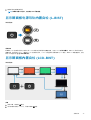
Thunderbolt(通过 USB Type-C)
Thunderbolt 是一种硬件接口,可通过单一的连接组合数据、视频、音频和电力。Thunderbolt 将 PCI Express (PCIe) 和 DisplayPort
(DP) 组合到一个串行信号,并且额外提供 DC 电力,只需使用一根电缆。Thunderbolt 1 和 Thunderbolt 2 使用同一连接器作为 miniDP
(DisplayPort) 以连接外围设备,而 Thunderbolt 3 使用 USB Type-C 连接器。
图 1: Thunderbolt 1 和 Thunderbolt 3
1. Thunderbolt 1 和 Thunderbolt 2(使用 miniDP 接口)
2. Thunderbolt 3(使用 USB Type-C 接口)
带 USB Type-C 的 Thunderbolt 3
Thunderbolt 3 将 Thunderbolt 传输到 USB Type-C,速度高达 40 Gbps,可形成一个执行全部功能的小巧的端口 - 为任何对接、显示
屏或数据设备(例如外部硬盘)提供速度最快、功能最多的连接。Thunderbolt 3 使用 USB Type-C 连接器/端口来连接受支持的外围
设备。
1. Thunderbolt 3 使用 USB Type-C 连接器和线缆 - 外形小巧,功能多样
2. Thunderbolt 3 支持高达 40 Gbps 的速度。
3. DisplayPort 1.4 – 兼容现有的 DisplayPort 显示器、设备和线缆。
4. USB 供电 - 受支持计算机上高达 130 W。
带 USB Type-C 的 Thunderbolt 3 的主要功能
1. USB Type-C 上的 Thunderbolt、USB、DisplayPort 和电力,使用一根电缆(功能因不同的产品而异)。
2. USB Type-C 连接器和线缆外形小巧,功能多样。
3. 支持 Thunderbolt Networking(*功能因不同的产品而异)。
4. 最多支持 4 K 显示。
5. 高达 40 Gbps
注: 数据传输速度可能会因不同设备而异。
技术和组件 11

Thunderbolt 图标
图 2: Thunderbolt 图解变化
HDMI 2.0
本主题介绍高清多媒体接口 (HDMI) 2.0 及其功能和优势。
HDMI 是业界支持并且解压缩的全数字音频/视频接口。HDMI 在任何兼容的数字化音频/视频源(如 DVD 播放器或 A/V 接收器)与
兼容的数字化音频和/或视频显示器(如数字 TV (DTV))之间提供接口。适用于 HDMI TV 和 DVD 播放器的目标应用程序。主要优势
在于减少电缆数量和内容保护规定。HDMI 在单个电缆上支持标准、增强型或高清视频以及多信道数字音频。
HDMI 2.0 功能
• HDMI 以太网信道 — 将高速网络添加到 HDMI 链路,使用户能够充分利用已启用 IP 的设备,无需单独的以太网电缆
• 音频返回信道 — 允许 HDMI 连接的电视带有一个集成调谐器将“上游”音频数据发送到环绕立体声系统,无需单独的音频电缆
• 3D — 定义了用于主要 3D 视频格式的输入/输出协议,为真正的 3D 游戏和 3D 家庭影院应用程序铺平道路
• 内容类型 — 在显示屏与源设备之间实时传输各内容类型的信号,使电视能够基于内容类型优化画面设置
• 附加颜色空间 — 增加在数字摄影和计算机图形中所用附加颜色模型的支持
• 4K 支持 — 实现远超 1080p 的视频分辨率,支持下一代显示屏,将与许多商业影院使用的数字影院系统竞争
• HDMI Micro 连接器 — 一种新推出的、小型化连接器,适用于手机和其他便携设备,支持的视频分辨率高达 1080p
• 汽车连接系统 — 适用于汽车视频系统的新型电缆和连接器,旨在满足行驶环境的独特需求,提供高清画质
HDMI 的优点
• 优质 HDMI 可以传输未经压缩的数字音频和视频,实现最高、最清晰的画质
• 低成本 HDMI 提供数字接口的质量和功能,同时还以简单、成本高效的方式支持未经压缩的视频格式
• 音频 HDMI 支持多个音频格式,从标准立体声到多声道环绕立体声
• HDMI 将视频和多声道音频整合至一条电缆传输,消除了在 A/V 系统中同时使用多条电缆的成本、复杂性和无序
• HDMI 支持在视频源(如 DVD 播放器)与 DTV 之间的通信,实现了新的功能
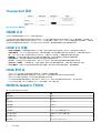
NVIDIA Quadro T1000
表
. 2: NVIDIA Quadro T1000
功能 值
图形内存 4 GB
核心 768
内存带宽 128 Gbps
内存类型 GDDR6
内存接口 128 位
时钟速率 1395 - 1455(睿频加速)MHz
GPU 基本时钟 8000 MHz(在 P0 时最小值)
估计最大功率 50 W
显示支持 eDP/mDP/HDMI/Type-C
12 技术和组件

表. 2: NVIDIA Quadro T1000(续)
功能 值
最大色深 高达 10 位/颜色
操作系统显卡/视频 API 支持 DirectX 12.0、OpenGL 4.6、DisplayPort 1.4、DirectX 12.1
支持的分辨率和最大刷新率 (Hz)
• 数字(最大值):单个 DisplayPort 1.4 - 7680 x 4320 (8k) @
30 Hz(mDP/Type-c 转 DP)
• 数字(最大值):双 DisplayPort 1.4 - 7680 x 4320 (8k) @ 60
Hz(mDP/Type-c 转 DP)
支持的显示屏数量 多达 4 个显示屏
NVIDIA Quadro RTX3000
表. 3: NVIDIA Quadro RTX3000
功能 值
图形内存 6 GB
核心 2304
内存带宽 336 Gbps
内存类型 GDDR6
内存接口 192 位
时钟速率 945 - 1380(睿频加速)MHz
GPU 基本时钟 3504 MHz(在 P0 时最小值)
估计最大功率 80 W
显示支持 eDP/mDP/HDMI/Type-C
最大色深 高达 10 位/颜色
操作系统显卡/视频 API 支持 DirectX 12.0、OpenGL 4.6、DisplayPort 1.4、DirectX 12.1
支持的分辨率和最大刷新率 (Hz)
• 数字(最大值):单个 DisplayPort 1.4 - 7680 x 4320 (8k) @
30 Hz(mDP/Type-c 转 DP)
• 数字(最大值):双 DisplayPort 1.4 - 7680 x 4320 (8k) @ 60
Hz(mDP/Type-c 转 DP)
支持的显示屏数量 多达 4 个显示屏
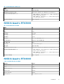
NVIDIA Quadro RTX4000
Table 4. NVIDIA Quadro RTX4000
Feature Values
Graphics memory 8 GB
Cores 2560
Memory bandwidth 448 Gbps
Memory type GDDR6
Memory Interface 256-bit
Clock Speeds 1110 - 1560 (Boost) MHz
技术和组件 13

Table 4. NVIDIA Quadro RTX4000(continued)
Feature Values
GPU base clock 14000 MHz
Estimated Maximum Power 100 W
Display Support eDP/mDP/HDMI/Type-C
Maximum Color Depth Up to 10 bit/color
Operating Systems Graphics/ Video API Support DirectX 12.0, OpenGL 4.6, DisplayPort 1.4, DirectX 12.1
Supported Resolutions and Max Refresh Rates (Hz)
• Max Digital : Single DisplayPort 1.4 - 7680 x 4320 (8k) @ 30 Hz
(mDP/Type-c to DP)
• Max Digital : Dual DisplayPort 1.4 - 7680 x 4320 (8k) @ 60 Hz
(mDP/Type-c to DP)
Numbers of Display Support Up to 4 displays
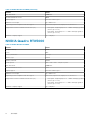
NVIDIA Quadro RTX5000
Table 5. NVIDIA Quadro RTX5000
Feature Values
Graphics memory 16 GB
Cores 3072
Memory bandwidth 448 Gbps
Memory type GDDR6
Memory Interface 256-bit
Clock Speeds 1035 / 1350 - 1545 / 1770 (Boost) MHz
GPU base clock 14000 MHz
Estimated Maximum Power 110 W
Display Support eDP/mDP/HDMI/Type-C
Maximum Color Depth Up to 10 bit/color
Operating Systems Graphics/ Video API Support DirectX 12.0, OpenGL 4.6, DisplayPort 1.4, DirectX 12.1
Supported Resolutions and Max Refresh Rates (Hz)
• Max Digital : Single DisplayPort 1.4 - 7680 x 4320 (8k) @ 30 Hz
(mDP/Type-C to DP)
• Max Digital : Dual DisplayPort 1.4 - 7680 x 4320 (8k) @ 60 Hz
(mDP/Type-C to DP)
Numbers of Display Support Up to 4 displays
14 技术和组件

拆卸和重新组装
SD 卡
卸下 SD 卡
前提条件
1. 按照“拆装计算机内部组件之前”中的步骤进行操作。
关于此任务
此图指示 SD 卡的位置,并提供拆卸过程的可视化表示。下个审查周期内将要上传的图像。
步骤
1. 按下 SD 卡,以将其从计算机中释放出来。
2. 将 SD 卡从计算机中滑出。
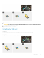
安装 SD 卡
前提条件
如果您要更换组件,请卸下现有的组件,然后再执行安装步骤。
关于此任务
此图指示基座护盖的位置,并提供安装过程的可视化表示。
下个审查周期内将要上传的图像
步骤
将 SD 卡滑入计算机上的插槽中,直至其卡入到位。
后续步骤
1. 按照“拆装计算机内部组件之后”中的步骤进行操作
SSD 盖板
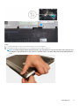
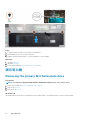
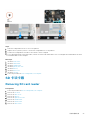
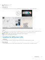
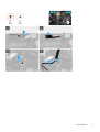
Removing SSD door
Prerequisites
1. Follow the procedure in before working inside your computer.
2. Remove the SD card.
About this task
The figure indicates the location of the SSD door reader and provides a visual representation of the removal procedure.
3
拆卸和重新组装 15

Steps
1. Push the SSD door towards left side to release the SSD door from the base cover.
2. Remove the SSD door from the base cover.
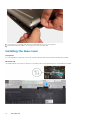
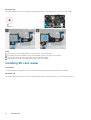
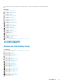
Installing SSD door
Prerequisites
If you are replacing a component, remove the existing component before performing the installation procedure.
About this task
The figure indicates the location of the SSD door and provides a visual representation of the installation procedure.
16
拆卸和重新组装

Steps
1. Place the SSD door into its slot on the base cover.
2. Push the SSD door towards right side to lock the SSD door.
Next steps
1. Install the SD card.
2. Follow the procedure in after working inside your computer.
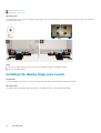
次要 M.2 固态硬盘
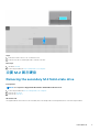
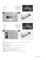
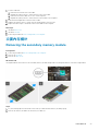
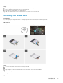
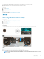
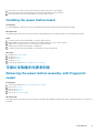
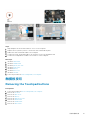
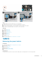
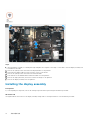
Removing the secondary M.2 Solid-state drive
Prerequisites
NOTE: For computers shipped with M.2 2280 or 2230 SSD installed in slot 6.
1. Follow the procedure in before working inside your computer.
2. Remove the SD card.
3. Remove the SSD door.
About this task
The figure indicates the location of the secondary M.2 SSD and provides a visual representation of the removal procedure.
拆卸和重新
组装 17

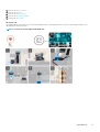
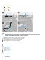
Steps
1. Slide the SSD release latch to unlock the SSD module.
2. Remove the (M2x3) screw that secures the SSD module into its slot on the computer.
3. Remove the SSD module from the computer.
4. Remove the (M2x3) screw that secures the SSD thermal pad to the SSD carrier.
5. Remove the SSD thermal pad from the SSD module.
6. For M.2 2280 SSD:
a. Remove the M.2 2280 SSD from the SSD carrier.
7. For M.2 2230 SSD:
a. Remove the M.2 2230 SSD with its holder from the SSD carrier.
b. Remove the (M2x2) screw to secure the M.2 2230 SSD to its holder.
c. Remove the SSD from the holder.
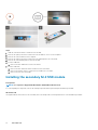
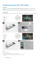
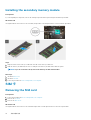
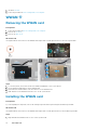
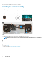
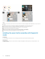
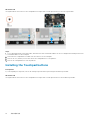
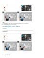
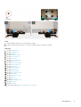
Installing the secondary M.2 SSD module
Prerequisites
NOTE: For computers shipped with M.2 2280 or 2230 SSD installed in slot 6.
If you are replacing a component, remove the existing component before performing the installation procedure.
About this task
The figure indicates the location of the secondary M.2 SSD and provides a visual representation of the installation procedure.
18
拆卸和重新组装

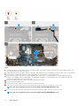
Steps
1. For M.2 2280 SSD:
a. Place the M.2 SSD onto its slot on SSD carrier.
2. For M.2 2230 SSD:
a. Place the M.2 SSD into the SSD holder.
b. Replace the (M2x2) screw to secure the M.2 SSD to the holder.
c. Place the M.2 SSD with its holder on the SSD carrier.
3. Place the thermal plate above the M.2 SSD module.
4. Replace the (M2x3) screw to secure the SSD thermal plate to the M.2 SSD.
5. Replace the SSD module in its slot on the computer.
6. Replace the (M2x3) screw to secure the SSD module in place.
Next steps
1. Install the SSD door.
2. Install the SD card.
3. Follow the procedure in after working inside your computer.
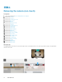
基座护盖
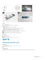
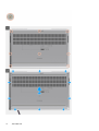
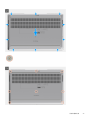
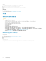
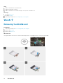
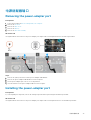
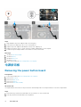
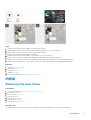
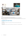
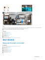
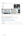
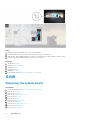
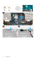
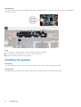
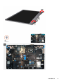
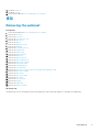
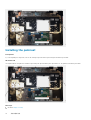
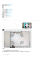
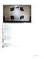
Removing the base cover
Prerequisites
1. Follow the procedure in before working inside your computer.
2. Remove the SD card.
About this task
The figure indicates the location of the base cover and provides a visual representation of the removal procedure
拆卸和重新
组装 19

20 拆卸和重新组装
ページが読み込まれています...
ページが読み込まれています...
ページが読み込まれています...
ページが読み込まれています...
ページが読み込まれています...
ページが読み込まれています...
ページが読み込まれています...
ページが読み込まれています...
ページが読み込まれています...
ページが読み込まれています...
ページが読み込まれています...
ページが読み込まれています...
ページが読み込まれています...
ページが読み込まれています...
ページが読み込まれています...
ページが読み込まれています...
ページが読み込まれています...
ページが読み込まれています...
ページが読み込まれています...
ページが読み込まれています...
ページが読み込まれています...
ページが読み込まれています...
ページが読み込まれています...
ページが読み込まれています...
ページが読み込まれています...
ページが読み込まれています...
ページが読み込まれています...
ページが読み込まれています...
ページが読み込まれています...
ページが読み込まれています...
ページが読み込まれています...
ページが読み込まれています...
ページが読み込まれています...
ページが読み込まれています...
ページが読み込まれています...
ページが読み込まれています...
ページが読み込まれています...
ページが読み込まれています...
ページが読み込まれています...
ページが読み込まれています...
ページが読み込まれています...
ページが読み込まれています...
ページが読み込まれています...
ページが読み込まれています...
ページが読み込まれています...
ページが読み込まれています...
ページが読み込まれています...
ページが読み込まれています...
ページが読み込まれています...
ページが読み込まれています...
ページが読み込まれています...
ページが読み込まれています...
ページが読み込まれています...
ページが読み込まれています...
ページが読み込まれています...
ページが読み込まれています...
ページが読み込まれています...
ページが読み込まれています...
ページが読み込まれています...
ページが読み込まれています...
ページが読み込まれています...
ページが読み込まれています...
ページが読み込まれています...
ページが読み込まれています...
ページが読み込まれています...
ページが読み込まれています...
ページが読み込まれています...
ページが読み込まれています...
ページが読み込まれています...
ページが読み込まれています...
ページが読み込まれています...
ページが読み込まれています...
ページが読み込まれています...
ページが読み込まれています...
ページが読み込まれています...
ページが読み込まれています...
ページが読み込まれています...
ページが読み込まれています...
ページが読み込まれています...
ページが読み込まれています...
-
 1
1
-
 2
2
-
 3
3
-
 4
4
-
 5
5
-
 6
6
-
 7
7
-
 8
8
-
 9
9
-
 10
10
-
 11
11
-
 12
12
-
 13
13
-
 14
14
-
 15
15
-
 16
16
-
 17
17
-
 18
18
-
 19
19
-
 20
20
-
 21
21
-
 22
22
-
 23
23
-
 24
24
-
 25
25
-
 26
26
-
 27
27
-
 28
28
-
 29
29
-
 30
30
-
 31
31
-
 32
32
-
 33
33
-
 34
34
-
 35
35
-
 36
36
-
 37
37
-
 38
38
-
 39
39
-
 40
40
-
 41
41
-
 42
42
-
 43
43
-
 44
44
-
 45
45
-
 46
46
-
 47
47
-
 48
48
-
 49
49
-
 50
50
-
 51
51
-
 52
52
-
 53
53
-
 54
54
-
 55
55
-
 56
56
-
 57
57
-
 58
58
-
 59
59
-
 60
60
-
 61
61
-
 62
62
-
 63
63
-
 64
64
-
 65
65
-
 66
66
-
 67
67
-
 68
68
-
 69
69
-
 70
70
-
 71
71
-
 72
72
-
 73
73
-
 74
74
-
 75
75
-
 76
76
-
 77
77
-
 78
78
-
 79
79
-
 80
80
-
 81
81
-
 82
82
-
 83
83
-
 84
84
-
 85
85
-
 86
86
-
 87
87
-
 88
88
-
 89
89
-
 90
90
-
 91
91
-
 92
92
-
 93
93
-
 94
94
-
 95
95
-
 96
96
-
 97
97
-
 98
98
-
 99
99
-
 100
100


