M
STAINLESS STEEL COMPRESSION LOAD CELL
NOTE
When the load cell is to be used with a tank or hopper
scale, be sure to provide a float-off protection.
1. INTRODUCTION
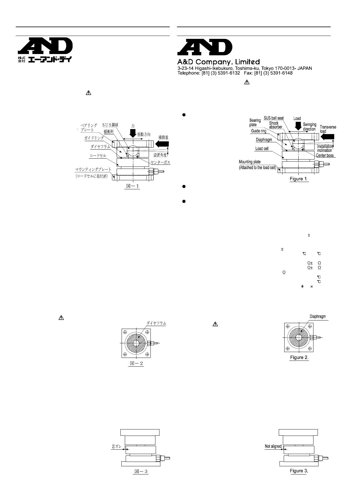
The LCC07 series stain-
less steel compression
load cells, with weld-
sealed construction, are
ideally suited for use in
harsh environments. Be-
cause the swing mecha-
nism and the transverse
load stopper are built in,
the load cell is easy to
handle and can be in-
stalled in a wide variety
of systems. It enables
accurate weighing in vari-
ous fields of application.
The transverse load stopper consists of a center boss and a guide ring.
When a transverse load acts on the guide ring, the ring hits the center
boss, which functions as a stopper.
To install the load cell properly, the static conditions, as well as dynamic
factors (i.e., shock and vibration) must be considered.
To obtain the best performance from the load cell, read this instruction
manual before installation.
2. SPECIFICATIONS
Rated capacities ............................. 5 kN,10 kN,20 kN,30 kN, 50 kN
Rated output ...............................................................2mV/V 0.1%
Maximum safe overload ................................ 150% of rated capacity
Combined error ................................................0.03% of rated output
Zero balance ..................................................... 1% of rated output
Compensated temperature range ...................................-10 to 40
Maximum excitation voltage....................................................... 12V
Input terminal resistance...................................................780 20
Output terminal resistance................................................700 10
Insulation resistance................................... 500M or over at 50VDC
Temperature effect on zero ........................ 0.004% of rated output/
Temperature effect on span .............................. 0.0014% of LOAD/
Cable thickness/length ...................................................... 5.6 5 m
Permissible installation inclination .................................... 2 degrees
Permissible swing range ..........................................................2 mm
Permissible transverse load ............................ 20% of rated capacity
Maximum permissible transverse load............. 50% of rated capacity
3. NOTES ON INSTALLATION
CAUTION
Do not apply a transverse load greater than
the permissible value described in the speci-
fications. If a transverse load, great enough
to make the stopper function often, exists
in the weighing system, be sure to provide
some measures such as a fastening rod.
When handling the load cell, be sure not to scratch the diaphragm.
Scratches on the diaphragm will result in load cell malfunctioning.
3-1 ATTACHING THE LOAD CELL
(1) Attach the load cell mounting plate to a rigid base horizontally.
The base should be rigid to prevent it from slanting or curving under
normal operating conditions.
If the base yields, the load cell will bend and adversely affect the system.
If foreign materials exist between the mounting plate and the base, the
load cell will be level. Remove the foreign materials, if any.
(2) Use M10 bolts to attach the mounting plate. Fasten it to the base se-
curely so that the plate will not loosen.
3-2 ATTACHING THE BEARING PLATE
(1) Attach the bearing plate with its
center exactly on the load cell
center. Check this by the position
of the load cell and the guide ring.
Their edges should be aligned.
(See Figure 3)


