
7040A
Operating Manual
操作手册
Genelec 7040A Active Subwoofer
真力 7040A 有源低音音箱

Introduction
Congratulation and thank you for choosing
Genelec!
Since 1978, Genelec has been guided by a
single idea – to make perfect active monitors
that deliver neutral and accurate sound in
every kind of acoustical environment. In
Genelec’s quest for this ultimate goal, our
unrivalled commitment to research and
development has led us to continuously
develop innovative driver technology,
electronic circuitry, enclosure designs and
many more. Our design philosophy is based
on sustainability and environmental values,
where industrial design serves our product
acoustical performance.
Your Genelec product has been designed
and manufactured with care in our factory,
in Finland, using environmentally efficient
solutions to give you reliable operation over
many years.
Please take the time to read this manual.
Happy monitoring!
General Description
The Genelec 7040A is a very compact active
subwoofer for reproducing low frequencies.
The 7040A extends the bass reproduction
of Genelec 8010, 8020 and M030 active
monitors for stereo applications. Using the
7040A extends their frequency responses
down to 30 Hz (-6 dB).
Driver
The 7040A contains one 165 mm (6.5
in) magnetically shielded driver, housed
in Genelec Laminar Spiral EnclosureTM
(LSE™).
Bass Management
Balanced XLR connectors are used for the
audio inputs and outputs. There are two
input connectors and two outputs.
The bass management unit in the 7040A
subwoofer splits the input into low and
high frequency components at 85 Hz.
Frequencies below 85 Hz are reproduced
by the subwoofer. Frequencies above 85
Hz are directed via the subwoofer's output
connectors to the main monitors. The
subwoofer's outputs have the same level as
the inputs.
The subwoofer sensitivity can be adjusted
from +12 to -6 dBu to match the subwoofer
sound level easily with different monitors.
Two "BASS ROLL-OFF" switches provide
bass response adjustment to compensate
for the acoustical environment in three 2
dB steps. Two switches allow alignment
of subwoofer phase with the monitors.
The phase can be adjusted in 90 degree
increments between 0° and -270°.
Amplier
A Class D power amplifier produces 50
W output power with very low THD and
IM distortions. Driver overload protection
is included in the amplifier circuitry. The
amplifier also incorporates thermal
overload and short circuit protections.
The power supply accepts mains voltages
from 100 to 240 VAC.
ISS™ Autostart
The 7040A is equipped with Intelligent
Signal SensingTM (ISS™) automatic
start function. ISS turns the amplifier
to standby mode if no input signal has
been detected for one hour. The power
consumption in standby mode is less
than 0.5 watts. Playback automatically
resumes once an input signal is detected.
There is a slight delay in the automatic
powering up. In those environments where
the 7040A is required to be on all of the
time, the ISS function can be disabled
by setting the “ISS DISABLE” switch to
the “ON” position. Then the subwoofer
is continuously powered and can be
turned off using the power switch on the
connector panel. The default position
from the factory is with "ISS DISABLE" in
the OFF position.
Installation
The subwoofer is supplied with a mains
cable and this operating manual. After
unpacking inspect the subwoofer for
possible damage in transport. Ensure
that the subwoofer and the monitors are
powered off before connecting cables.
Genelec 7040A Active Subwoofer

Audio connections to the subwoofer and
monitors use balanced XLR cables (not
included in the subwoofer delivery content).
As the 7040A has an integrated amplifier,
it may only be connected to a line level
signal source, such as a mixing console or
preamplier, never to the loudspeaker outputs
of a power amplier or an integrated amplier.
The source is connected to the "LEFT IN"
and "RIGHT IN" connectors of the subwoofer.
The subwoofer’s output connectors "LEFT
OUT" and "RIGHT OUT" are connected to the
monitors.
If the signal source has unbalanced RCA
outputs, you can use signal cables as shown
in Figure 2.
Once all connections have been made, the
subwoofer and monitors can be powered up.
Positioning In The Room
Placement of the subwoofer in the room
affects the subwoofer frequency response
and sound level dramatically, as the room
influences the low frequencies strongly.
Even a slight change in the subwoofer's
location can make a marked difference in
the frequency balance. Often patient and
methodical experimentation is needed to
nd the optimum placement. The placement
will also affect the phase alignment between
the monitors and the subwoofer, as well as
the need for bass roll-off adjustment.
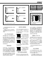
First, place the subwoofer slightly offset
from the center of the front wall. The
distance to the nearest wall should be
less than 0.6 m (24 in) measured from the
subwoofer's driver. This position increases
acoustic loading and sound output due
to the proximity of the wall and floor. Too
large a distance from the wall can cause
cancellations and reduce subwoofer output.
The monitor should be placed at least 1.1 m
(43 in) away from walls to avoid reduction of
low frequency output (see Figure 3).
If the subwoofer frequency response does
not seem balanced, move the subwoofer
slightly to the left or right. This changes
how the room modes are excited and can
result in improved flatness. Positioning
the subwoofer close to a corner boosts
the subwoofer output but may cause
asymmetrical spatial imaging at low
frequencies.
Operating Environment
The 7040A subwoofer is designed for indoor
use only. The ambient temperature should
be 15-35 °C (50-95 °F) and the relative
humidity 20-80 %. Condensation is not
allowed. If it has been stored or transported
in a cool environment, the product must be
allowed to warm up in its packing to the
ambient temperature before connecting
mains power.
Sufficient amplifier cooling and reflex
port functioning is required when the
>110 cm (43 in)
Main
monitor
<60cm (24 in)
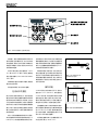
Figure 3. Recommended distances to
the front wall
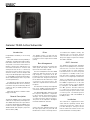
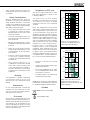
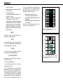
Figure 1. 7040A's amplifier panel, connectors and controls.
Figure 2. XLR to RCA connector for
connecting to an unbalanced signal source.
MADE IN FINLAND
www.genelec.com
7040A ACTIVE SUBWOOFER
MAGNETICALLY SHIELDED
SERIAL
NUMBER
LEFT OUT
LEFT IN
RIGHT OUT
RIGHT IN
POWER
ON
ROLL-OFF
-180°
-90°
-4 dB
-2 dB
-270°
ISS-DISABLE
MAINSINPUT
50 /60Hz70W
100 - 240 V~
-6
0
+6
+3
+12
-3
-4
dBu
SENSITIVITY
FOR 100 dB
SPL @1m
SIGNAL INPUT
CONNECTORS
SIGNAL OUTPUT
CONNECTORS
BASS ROLL-OFF
PHASE AND
ISS DISABLE
SWITCHES
MAINS INPUT
POWER SWITCH

ON
OFF
ON
OFF
ON
OFF
subwoofer is installed in a restricted space,
such as a cabinet or integrated into a wall
structure. See section “Flush Mounting the
Subwoofer.” A restricted space must be
sufficiently ventilated to prevent ambient
temperature rise above 35 °C (95 °F).
Do not cover the driver of the subwoofer.
Do not place the subwoofer so that there is
less than 10 cm (4 in) of free space in front
of the grille.
Thick carpets under the subwoofer can
block the ventilation clearance needed for
cooling the amplifier unit. To ensure proper
functioning of the reex port the reex port
side (opposite of the connector panel) should
have a minimum clearance of 7.5 cm (3 in).
Flush Mounting the
Subwoofer
If the subwoofer is flush mounted into a
wall or a cabinet, ensure amplier cooling
and unrestricted airflow from the reflex
port. Make the recess 7.5 cm (3 in) wider
than the subwoofer. Place the subwoofer
into the right end of the recess with the
driver side facing the room. This leaves
sufcient 7.5 cm (3 in) of free space for the
reflex port. The height and depth of the
recess should not be much larger than the
subwoofer.
Setting the Input Sensitivity
The 7040A has the same sensitivity as
8010, 8020 and M030 monitors in free
eld. However, when placed near reecting
surfaces the sensitivity of 7040A typically
must be attenuated due to increased
wall loading. A typical initial setting for
the rotary sensitivity control is -4 dBu.
The +12 dBu setting provides maximum
attenuation The use of proper measuring
equipment with careful listening is highly
recommended.
Phase Alignment by
Listening
Connect an audio frequency signal
generator to LEFT IN or RIGHT IN input
of the 7040A and feed in an 85 Hz tone.
Connect a monitor to the corresponding
output, so that the test signal is reproduced
by both subwoofer and monitor.
Toggle the -180°
phase switch (DIP 4
from left) "ON" and
"OFF". Set it to the
position giving the
lowest sound level at
the listening position.
Next, toggle the -90°
phase switch (DIP
3) "ON" and "OFF",
and again set it to the
position which gives
the lowest sound level.
Finally, invert the
-180° phase switch
(DIP 4) position to the
opposite setting. Now
you can remove the
test signal.
Phase Alignment Using Test
Equipment
Feed in the test signal to LEFT IN or RIGHT
IN of the subwoofer. Place the microphone
at the listening position. Using a real-
time analyser or other frequency response
measurement system, adjust the sensitivity
of the subwoofer until the frequencies
below and above 85 Hz are reproduced
at equal level. Then, adjust the phase
switches for the maximum dip of at least
-6 dB at the crossover frequency (85 Hz).
Invert the -180° switch to the opposite
setting. The phase is now aligned and
the measurement should show a smooth
response around 85 Hz.
Setting the Bass Roll-Off
The acoustic response of the subwoofer
can compensate the room characteristics.
To adjust the subwoofer use the ''Bass
Roll-Off' switches located on the
connector panel. These offer attenuation
levels of -2, -4, and -6 dB at the lowest
subwoofer output frequencies. Table 1
provides suggestions for Bass Roll-Off
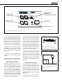
Figure 4. The effect of phase difference between the subwoofer and the main loudspeakers
Phase Difference: 0°
85 Hz
Phase Difference: 180°
85 Hz
Phase Difference: 270°
85 Hz
Phase Difference: 90°
85 Hz
Figure 5. Flush mounting the subwoofer.
Note the clearance needed on the reflex
port side.
Table 1. Suggested Bass Roll-Off settings
Subwoofer placement
Bass Roll-Off
setting
Near to a wall -2 dB
In a corner -6 dB
Flush mounted -2 dB

switch settings. Flat anechoic response is
obtained when both roll-off switches are
set to "OFF".
Safety Considerations
Genelec 7040A subwoofer has been
designed in accordance with international
safety standards. However, to ensure safe
operation and maintain the unit in safe
operating condition, the following warnings
and cautions must be observed:
• Do not expose the subwoofer to water
or moisture. Do not place any objects
lled with liquid, such as vases on the
subwoofer or near it.
• Servicing and adjustment must only
be performed by authorized Genelec
service personnel.
• Opening the amplifier unit is strictly
prohibited except by authorized service
personnel.
• Always use a mains power connection
with protective earth terminal. In case
of fault, failing to do this may lead to
personal injury.
• Free ow of air around the subwoofer
is necessary to maintain sufficient
cooling. Do not obstruct airow around
the subwoofer.
• Note that the subwoofer is not
completely disconnected from the AC
mains service unless the mains power
cord is removed from the amplifier or
the mains outlet. Easy access to either
end of the power cord must be ensured
at all times.
Warning!
This equipment is capable of delivering
sound pressure levels in excess of 85
dB, which may cause permanent hearing
damage.
Maintenance
No user serviceable parts are inside the
amplifier unit. Any maintenance of the
unit must only be performed by Genelec
authorized service personnel.
Guarantee
This product is supplied with a two year
guarantee against manufacturing faults or
defects that might alter the performance.
The guarantee can be extended to five
years by registering the product on www.
genelec.com. Refer to the supplier for full
sales and guarantee terms.
Compliance to FCC rules
This device complies with part 15 of the
FCC Rules. Operation is subject to the
following conditions:
This device may not cause harmful
interference, and this device must accept
any interference received, including
interference that may cause undesired
operation.
Note: This equipment has been tested
and found to comply with the limits for a
Class B digital device, pursuant to part
15 of the FCC Rules. These limits are
designed to provide reasonable protection
against harmful interference in a residential
installation. This equipment generates, uses
and can radiate radio frequency energy
and, if not installed and used in accordance
with the instructions, may cause harmful
interference to radio communications.
However, there is no guarantee that
interference will not occur in a particular
installation. If this equipment does cause
harmful interference to radio or television
reception, which can be determined by
turning the equipment off and on, the user is
encouraged to try to correct the interference
by one or more of the following measures:
• Reorient or relocate the receiving
antenna.
• Increase the separation between the
equipment and receiver.
• Connect the equipment into an outlet
on a circuit different from that to which
the receiver is connected.
• Consult the dealer or an experienced
radio/TV technician for help.
Modications not expressly approved by the
manufacturer could void the user’s authority
to operate the equipment under FCC rules.
Symbols
WEEE Directive 2012/19/EU
Power/standby switch
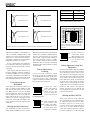
Figure 7. The curves above show the
harmonic distortion analysis of the
7040A in free field. In half space the SPL
will be 6 dB higher.
Figure 6. The free field frequency
response of the 7040A subwoofer at
different Bass Roll-Off settings
Harmonicdistortion 7040A 25.3.15
+0
+100
+20
+40
+60
+80
10
200
20
30
50
100
Hz
Fundamental
frequency
2nd harmonic
3rd harmonic
dB SPL
Frequency response 7040A 25.3.15
+0
+100
+20
+40
+60
+80
10
200
20
30
50
100
Hz
dB SPL

7040A Operating Manual
Amplifier Section
input Section
croSSover Section
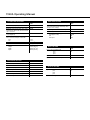
SyStem SpecificAtionS
7040A
Free eld frequency response (-6 dB) 30...90 Hz
Accuracy of frequency response ± 3 dB (33...85 Hz)
Maximum short term sine wave SPL output
averaged from 40 to 85 Hz, measured in half
space at 1 meter
100 dB
Self generated noise level in half space at
1 m (A-weighted)
≤ 5 dB
Harmonic distortion at 90 dB SPL
at 1 m on axis in half space 40…85 Hz
2nd
3rd
≤ 2.5%
≤ 1.5 %
Driver, magnetically shielded 165 mm (6
1
/
2
in)
Weight 11.3 kg (24.9 lb)
Dimensions
Height
Width
Depth
410 mm (16
1
/
8
in)
350 mm (13
3
/
4
in)
205 mm (8
1
/
16
in)
output Section
7040A
Subsonic lter (18 dB/octave) below 35 Hz
Input channels 2
High pass frequency for main channel outputs 85 Hz
Midband rejection >400 Hz ≥ 50 dB
Bass Roll-Off control in 2 dB steps 0 to -6 dB @ 35 Hz
Phase matching control in 90° steps 0 to -270°
Input sensitivity control +12 to -6 dBu
7040A
Amplier short term output power
(Long term output power is limited by driver
unit protection circuitry)
50 W
Amplier system THD at nominal output ≤ 0.08 %
Mains voltage 100 - 240 VAC universal
Power consumption (average)
Standby (ISS active)
Idle
Full output
≤ 0.5 W
5 W
70 W
7040A
Input connectors XLR female
pin 1
pin 2
pin 3
gnd
+
-
Input impedance 10 kohm balanced
Input level for 100 dB SPL output @ 1 m Variable from +12 to -6 dBu
7040A
Input connectors XLR male
pin 1
pin 2
pin 3
gnd
+
-
Main monitor Out gain 0 dB

介绍
感谢您选择真力(Genelec)产品!
自1978年起,真力就遵循着一个理念⸺
制造最好的有源监听音箱,在各种各样的声
学环境中提供自然、精准、中性的声音重放。
为了实现这一终极目标,多年来我们在研发
上投入了不遗余力的努力,在单元技术、电子
电路技术和箱体设计等方面引领行业前沿。
我们坚持环保和可持续发展的设计理念,同
时,产品的工业设计为产品的声学性能服务。
您的这件真力产品是在位于芬兰的真力
工厂精心设计,并选用最优的环保材料制
造而成的。它值得信赖,经久耐用,可以长
久地陪伴您。
请您抽时间阅读这本操作手册。祝您聆
听愉快!
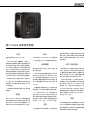
概述
真 力( Genelec)7040A是一款非常紧凑的
有源低音音箱,用于重放低频内容,适合搭
配真力8010、8020、M030音箱组成2.1立
体声系统,将低频下潜扩展至30Hz(-6dB)。
单元
7040A带有一个165mm(6.5 in)防磁型单
元,安装在真力LSE™层状螺旋式箱体中。
低频管理
输出采用平衡XLR接口。共有2个输入和
两个输出接口。
7040A中的低频管理模块将输入信号分
成85Hz以上和85Hz以下两个部分。85Hz
以下内容由低音音箱重放。85Hz以上内
容由低音音箱通过输出接口送出给主音
箱。低音音箱的输出电平与信号输入电
平一致。
低音音箱的灵敏度可以在+12到6dBu范
围内调节,与不同的主音箱进行音量匹配。
2个“ BASS ROLL-OFF”(低频滚降)开
关以2dB为一阶共有3个档位,用于针对实
际声学环境进行频率响应补偿调整。同时,
还有两个开关用于调整与主音箱的相位匹
配 ,有 0
°
、-90
°
、-180
°
、-270
°
共4个档位。
功放
7040A具有50W的D类功放,THD失真度及
MI失真度极低。功放电路中带有单元过载
保护。同时,功放中还带有过热保护和短路
保护。主电源为自适应电源,100~240VAC
均可适用。
ISS™自动待机
7040A带有ISS™智能信号监测自动待机
功能。当监测到一段时间内没有音频信号
时,音箱自动切换到待机状态。音箱在待机
模式下的功耗小于0.5W。当再次接收到音
频信号时,音箱自动切换回工作状态。
从待机到开启有一个极短暂的延时。
如果您的工作环境中需要7040A长期保
持开启状态,请将“ISS DISABLE”开 关
调整到“ON”,将自动待机功能关闭。此
时,7040A将不会进入待机状态,您可以
使用接线面板上的电源开关来关闭音箱。
通常,音箱的出厂设置为“ISS DISABLE”
开关在“OFF”状 态 。
安装
7040包装箱中附带一根电源线和一份安装
手册。打开包装箱后,请您检查是否存在运输
途中造成的损坏。在接线之前,确保低音和音
箱的电源开关均处于关闭位置。
真力 7040A 有源低音音箱

音频输入、输出均需要使用带有平衡XLR
接口的线缆(包装箱中不含)。由于7040A带
有内置功放,请务必将其与低电平线路信号
相连接,如调音台、前级,请勿将7040A与功
放的输出相连接。
请将声源连接至低音音箱的“LEFT
IN”和“ RIGHT IN”接口。请将主音箱连
接至低音音箱的“LEFT OUT”和“ RIGHT
OUT”接 口 。
如果声源设备为非平衡RCA输出,请使用
图2中的信号线缆。
所有连接完成后,您可以开启音箱。
在房间中的摆位
由于房间对低频的影响巨大,因此低音音
箱在房间中的摆位显著影响着低频的频率
响应和声压级。即便是很小的改变,也可能
引起低频表现的显著变化。通常,您需要使
用系统的方法耐心找到低音音箱的最理想
摆位。同时,摆位也影响着主音箱与低音音
箱之间的相位匹配,以及是否需要使用低
频滚降设置。
首先,将低音音箱偏离前墙的中心摆放。
从低音音箱单元到最近墙面的距离应小于
0.6m(24 in)。由于墙面和地面的反射作用,
这种摆位可以提升低频声压级。如果低音音
箱离墙面的距离过远,可能会引起低音抵消
现象,并降低低频声压级。在使用低音音箱的
情况下,主音箱离墙面的距离最好大于1.1m,
以避免低频抵消现象(见图3)。
如果低频响应不够均衡,可以尝试左右
移动低音音箱。这将改变房间中激起的各
种驻波,并可能得到更平直的频率响应。将
低音音箱放置在房间角落,会让低频声压
级显著增加,但可能引起低频在空间中分
布不均的现象。
操作环境
7040A是为室内使用而设计的,适用于
温度为15-35
°
C(50-95
°
F),相对湿度为
20-80%的环境。不可耐受冷凝环境。如果
音箱在运输、储存过程中处于寒冷环境,
请务必保持原包装封闭,并将其放置在正
常温度下进行恢复,然后再连接主电源。
当把音箱进行嵌入式安装或柜式安装时,
需为功放留出通风散热空间,确保环境温度
在35
°
C(95
°
F)以下。同时,需为倒相孔留出
空气流动的缝隙,以确保音箱正常工作。请
参考“嵌入式安装低音音箱”。
不要遮盖音箱的单元。音箱格栅前方的
开放空间不要小于10cm(4 in)。
图例1:7040A的功放面板、连接口和控制钮
图例2:为非平衡输出设计的
XLR转RCA信号接头
图例3:低音与前墙面的最佳距离

将低音音箱放置在厚重的地毯上可能会
阻碍功放的散热。
为确保倒相孔的正常工作,请在倒相孔一
侧(接线面板的对侧)至少留出7.5cm(3 in)
的缝隙。
嵌入式安装低音音箱
如果把音箱进行嵌入式安装或柜式安装,需
确保为功放留出散热空间,并确保倒相孔的
正常空气流动。嵌入槽的宽度或柜体的宽度
需比音箱宽度至少多出7.5cm(3 in)。安 装
时,请确保正确的安装方向,音箱单元一侧
指向房间内部,倒相孔一侧留出缝隙。嵌入
槽或柜体的高度和深度最好不要比低音安
装所需要的更多。
灵敏度设定
在自由声场中,7040A低音音箱具有与
8010、8020和M030音箱相同的灵敏度。当
被放置在靠近反射面的位置时,由于墙面反
射的作用,您通常需要将7040A的灵敏度降
低一些。建议的初始设置为,将灵敏度旋钮调
整到-4dBu位置。将旋钮调整到+12dBu将使
音箱灵敏度衰减到最低。建议您使用合适的
测量设备,并配合细心的主观聆听。
通过聆听设置相位
将85Hz测试信号连接到7040A的LEFT IN
或 RIGHT IN 音频输入上。将相应的7040A
输出连接到主音箱。此时,7040A与主音箱
同时播放测试信号
将-180
°
相位开关(左数
第4个DIP开关)分别拨
动 到“ ON”和“ OFF”进
行聆听,并将开关设置
到在听音位置上获得最低声压级的档位上。
然 后 ,将 -90
°
相位开
关(左数第2 个DIP开
关)分别拨动到“ON”
和“ OFF”进行聆听,
并将开关设置到在听音位置上获得最低
声压级的档位上。
最 后 ,将 -180
°
相位开关
(左数第4个DIP开关)
拨动到相反的位置,并
断开测试信号。
通过测量设备设置相位
使用实时分析仪或其他频率响应测量设备,
将85Hz测试信号连接到7040A的LEFT IN 或
RIGHT IN 音频输入上。将话筒放置在听音
位置。调整低音音箱的灵敏度,使得85Hz以
上和以下的声压级相同。然后调整相位开关,
使得分频点上(85Hz)产生最大的衰减(至少
衰减6dB)。将 -180
°
开关拨动到相反位置。至
此相位调整完成,测试设备上应显示出85Hz
附近具有平滑的频率响应。
设置Bass Roll-Off
低音音箱的声学表现可以对房间的声学缺
陷进行一定的补偿。您可以使用接线面板
上 的“ Bass Roll-Off”(低频滚降)开关进行
调整。它能在极低频段进行-2、-4、-6dB的衰
减 。表 1提供了Bass Roll-Off开关的设置建
议。当所有开关都设置在“OFF”时,低音音箱
能够在自由声场中具有平直的响应。
将85Hz测试信号连接到7040A的LEFT
IN 或 RIGH
安全注意事项
7040A严格按照国际安全标准设计,但您仍
需注意以下警告和注意事项,确保安全的操
作以及安全的音箱工作条件:
• 切勿将音箱靠近水或潮湿环境。切勿在
音箱上或其附近任何地方摆放装有液体
ON
OFF
ON
OFF
ON
OFF
图例4:低音与主音箱之间不同相位所产生的效果
图例5:低音嵌入式安装。请注意低频反相孔一
侧需要足够的散热空间
表格1:厂家推荐的不同音箱安装情况下的不同低频
滚切设置
低音摆放位置 低频滚降设置
靠近墙面 -2 dB
在墙角 -6 dB
嵌入式安装 -2 dB

的物品,例如花瓶。
• 音箱维修和调整必须由具有维修资质
的人员来完成。
• 切勿自行拆开音箱。
• 切勿使用未连接保护地的电源线,这可
能会危机人身安全。
• 此音箱可以产生超过85dB的声压级,
这可能会引起永久性听力损伤。
• 低音周围的空气流通很重要,请确保音
箱周围有足够的通风空间。请不要在音
箱周围放置任何有碍空气流通的障碍物。
• 请注意,除非将电源线从功放上或电源
插座上拔掉,否则功放并未完全与交流
电源断开连接。
警告!
此音箱可以产生超过85dB的声压级,这可
能会引起永久性的听力损伤。
维护
在音箱内部没有任何用户可自行维护的部
分。任何关于音箱的维护或维修都应由真
力授权的维修服务人员来完成。
质保
产品为材料和工艺上的瑕疵提供2年质保。
请参考供货商的销售和质保条款。
FCC符合性声明
该设备符合FCC规定的第15部分。操作必须
符合以下两个条件:
(1)此设备不造成有害干扰
(2)设备必须接受所收到的干扰,包括可能
导致意外操作的干扰
注意:该设备已经经过测试,符合B类数字
设备的限制,且符合FCC标准第15部分的
要求。这些限制旨在提供合理的保护,防止
在住宅区安装时产生有害干扰。该设备会
产生,使用和辐射射频能量,如果未按照说
明安装和使用,则可能对无线通信造成有
害干扰。但是,我们不保证在特定安装中不
产生干扰。如果设备对无线电和电视的接
受产生有害的干扰,用户可通过开关该设
备进行验证,我们建议用户采用下述中一
种或多种手段进行干扰消除:
• 重新调整天线的方向和位置
• 加大该设备与接收器之间的距离
• 将该设备和接收器分别连接到不同电
路的插座上
• 向经销商或有经验的无线电/电视技术
人员寻求帮助
任何未经厂方许可的改动都将让用户丧失
在FCC规定下操作设备的权力。
图例7:上图中的曲线显示的是7040A低音在
自由声场中的谐波失真分析结果。在半空间
中,SPL会高出6dB
图例6:7040A低音不同低频滚切设置情况
下的自由声场中的频率响应
Harmonicdistortion 7040A 25.3.15
+0
+100
+20
+40
+60
+80
10
200
20
30
50
100
Hz
Fundamental
frequency
2nd harmonic
3rd harmonic
dB SPL
Frequency response 7040A 25.3.15
+0
+100
+20
+40
+60
+80
10
200
20
30
50
100
Hz
dB SPL

7040A 低音使用手册
Genelec Document D0126R001 Copyright Genelec Oy 3.2015. All data subject to change without prior notice
www.genelec.com
International enquiries:
Genelec, Olvitie 5
FIN-74100, Iisalmi, Finland
Phone +358 17 83881
Fax +358 17 812 267
Email [email protected]
In the U.S. please contact:
Genelec, Inc., 7 Tech Circle
Natick, MA 01760, USA
Phone +1 508 652 0900
Fax +1 508 652 0909
Email [email protected]
真力中国
北京市朝阳区酒仙桥路10号
恒通商务园 B33-101
电话 400 700 1978
微信 真力GENELEC
微博 @真力GENELEC
Email [email protected]
功放部分
输入部分
分频部分
系统参数
7040A
自由场频率响应(-6 dB) 30...90 Hz
频率响应精准度:
±
3 dB (33...85 Hz)
最大短期正弦波SPL输 出( 40 Hz – 85 Hz均 值 ,半
开放声场,轴上1m处)
100 dB
自身噪音(半开放声场,轴上1m处,A计权) ≤ 5 dB
总谐波失真 at 85dB SPL
(40 Hz – 85 Hz均值,半开放声场,轴上1m处)
2次
3次
≤ 2.5%
≤ 1.5 %
驱动单元(带有磁屏蔽) 165 mm (6
1
/
2
in)
重量 11.3 kg (24.9 lb)
尺寸
高度
宽度
深度
410 mm (16
1
/
8
in)
350 mm (13
3
/
4
in)
205 mm (8
1
/
16
in)
输出部分
7040A
低频滤波器(18 dB/octave)低 于 35 Hz
输入通道 2
主声道高通滤波器 85 Hz
中频抑制>400 Hz ≥ 50 dB
低频滚降调整,2dBstep 0至-6 dB @ 35 Hz
相位匹配调整,90
°
step 0至270
°
输入灵敏度调整 +12 dBu 至 -6dBu
7040A
功放短期输出功率
(长期输出功率受限于单元保护电路)
50 W
额定输出下的功放系统THD ≤ 0.08 %
电源电压 100 – 240V 交流电
功耗(平均)
待 机( ISS开启)
闲置
全输出
≤ 0.5 W
5 W
70 W
7040A
输入接口XLR(母)
pin 1
pin 2
pin 3
gnd
+
-
输入阻抗 10 kohm 平衡
在1m处获得100dB SPL时的输入电平 +12 dBu 至 -6dBu 可调
7040A
输入接口XLR(公)
pin 1
pin 2
pin 3
gnd
+
-
主音箱输出增益 0 dB
In Sweden please contact
Genelec Sverige
Ellipsvägen 10B
P.O. Box 5521, S-141 05 Huddinge
Phone +46 8 449 5220
Fax +46 8 708 7071
Email [email protected]

-
 1
1
-
 2
2
-
 3
3
-
 4
4
-
 5
5
-
 6
6
-
 7
7
-
 8
8
-
 9
9
-
 10
10
-
 11
11
-
 12
12


他の言語で
関連論文
-
Genelec G Three and F Two Stereo System 取扱説明書
-
-
-
-
-
Genelec S360, 8351 and 7380 Immersive System 取扱説明書
-
-
-
Genelec G Three and F Two Stereo System 取扱説明書
-