Grandstream GDS3710V2 インストールガイド

タイプ
インストールガイド

Grandstream GDS3710V2 は、高画質の IP ビデオ ドア システムで、ビジネスや住宅のセキュリティを強化するために必要な機能を備えています。1080p フル HD カメラと広角レンズを搭載し、昼夜を問わず鮮明な映像をキャプチャできます。また、赤外線 LED とモーション センサーも内蔵されているため、暗闇や人の動きを検知したときにアラートを発信することができます。

GDS3710V2 は、使いやすい Web インターフェイスを備えており、どこからでもリモートでアクセスしてドアのロックやロック解除、ライブ映像の視聴、録画の再生を行うことができます。また、スマートフォンやタブレットにアプリをインストールして、携帯端末からドアを制御することも可能です。

GDS3710V2 は、セキュリティを強化したいあらゆる場所の最適なソリューションです。オフィス、店舗、アパート、一軒家など、

For Warranty and RMA information, please visit
www.grandstream.com
Grandstream Networks, Inc.
126 Brookline Ave, 3rd Floor
Boston, MA 02215. USA
Tel : +1 (617) 566 - 9300
Fax: +1 (617) 249 - 1987
www.grandstream.com
GDS3710
Hemispheric HD IP Video Door System
Quick Installation Guide
Content
English......................................................1
简体中文................................................11
Español..................................................21
Français.............................................31
Deutsch................................................41
Italiano................................................51
Русскй................................................61
Português............................................... 71
Polski.......................................................81
~1~ ~2~
EN
PRECAUTIONS
PACKAGE CONTENTS
Do not attempt to disassemble or modify the device
• Strictly follow the requirement of power source
• Do not expose this device to temperatures out the range of
-30 °C to 60 °C for operating and -35°C to 60°C for storage
• Do not expose this device to environments outside of the
following humidity range: 10-90% RH (non-condensing)
• Please strictly follow the instruction to install or hire
professionals to install properly
1 x GDS3710
1 x Quick Installation Guide
1 x GPL License
1 x Installation
Bracket
1 x RFID Card
1 x RFID Key Fob
4 x Rubber Gaskets 6 x Bracket Screws
and Anchors
6 x Back Panel Screws
4 x Anti-tamper
Screws
1 x Anti-tamper
Hex Key
1 x Drilling
Template
1 x Wiegand
Cable
1 x Frame Back Cover
MOUNTING GDS3710
Step 2:
Pull Cat5e or Cat6 cable (not provided) through the rubber gasket
selecting the correct size and the back cover panel piece, please re-
fer to “GDS 3710 WIRING TABLE” at the end of QIG for Pin connections.
Step 1:
Refer to the “drilling template” to drill holes at targeted place on
wall then mount the installation bracket using the four screws and
anchors provided (screwdriver not provided). Connect and tight-
en “Ground” wire (if available) to the bracket ground marked with
printed icon .
On-Wall (Surface) Mounting
Note:
Needle nose plier highly recommended and 2.5mm at screwdriver
required (not provided). Stripping outer plastic shield of the cable
in less than 2 inches suggested. Do NOT leave bare metal outside
the socket by over stripping the inner plastic shield of the wires.
1 x Protecting Cap
1 x Lens Cleaning
Cloth
~3~ ~4~
Step 3:
Make sure the ”Back Cover Frame” is in place, the wired back
cover panel is good. Flush the back cover panel piece with the
whole back surface of device, tighten it using the screws provided.
Step 4:
Take out the two preinstalled anti-tamper screws using the hex key
provided. Carefully align the GDS3710 to the metal bracket on
wall, press and pull the GDS3710 down to the right position.
Step 5:
Install the two anti-tamper screws back using the hex key provided
(do NOT over tighten the screws). Cover the two screw holes on
the bottom of “Back Cover Frame” piece using the two silicon
plugs provided. Final check and nish the installation.
In-Wall (Embedded) Mounting
Please refer to the “In-Wall (Embedded) Mouting Kit”,
which can be purchased separately from Grandstream.
CONNECTING THE GDS3710
Refer to the illustration below and follow the instruc-
tions on the next page.
Note:
Choose Option A if using PoE switch (Class 3);
OR: Option B if using 3rd party power source.
Option B:
DC12V, 1A minimum
Power Source
(not provided)
Option A:
RJ45 Ethernet Cable to (Class 3) Power over Ethernet
(PoE) Switch.
Network Port Power Port
12V
POWER OFF GDS3710 when connecting wires or
inserting/removing the back cover panel piece!
(4) KM2*5mm
~5~ ~6~
Option A
Plug an RJ45 Ethernet cable into the (Class 3) Power
over Ethernet(PoE) switch.
Option B
Step 1:
Select an external DC12V, minimum 1A power source
(not provided). Wire correctly the “+,-” cable of the pow-
er into the “12V, GND“ connector of the GDS3710 socket
(refer to the previous mounting page for instruction). Con-
nect the power source.
Step 2:
Plug an RJ45 Ethernet cable into a network switch/hub
or router.
Note:
Please refer to “Step 2” of “MOUNTING GDS3710” and
“GDS3710 WIRING TABLE“ at the end of QIG for all the wiring
and connection illustration and instructions.
GDS3710 CONFIGURATION
The GDS3710 is by default congured to obtain the IP
address from DHCP server where the unit is located.
In order to know which IP address is assigned to your
GDS3710, please use GS_Search tool as illustrated in fol-
lowing steps.
Note:
If no DHCP server is available, the GDS3710 default IP ad-
dress (after 5 minutes DHCP timeout) is 192.168.1.168.
Step 1: Download and install GS_Search tool:
Step 2: Run the Grandstream GS_Search tool on
a computer connected to same network/
DHCP server.
Step 3: Click on button to start device
detection.
Step 4: The detected devices will appear in the
output eld as below.
http://www.grandstream.com/support/tools
~7~ ~8~
Step 5: Open the web browser and type the displayed IP
address of GDS3710 with leading https:// to access the
web GUI. (For security reasons, the default web access
of GDS3710 is using HTTPS and port 443.)
Step 6: Enter username and password to login.
(The default administrator username is “admin” and the
default random password can be found at the sticker on
the GDS3710).
Note: For security reasons, make sure to change the de-
fault admin password from System Settings > User Man-
agement.
Step 8: To view video feed, access to LiveView . The
browser will indicate that Active-X or Video Plug-in is re-
quired. Follow the displayed instruction to download and
install it.
Click “Play” button to view the selected video feed.
Below is an example screenshot with the successful Ac-
tive-X or Plug-in installation.
Refer to online documents and FAQ for more
detailed information:
Step 7: After login into the webGUI, click the left side
menu in the web interface for more detailed and ad-
vanced conguration. http://www.grandstream.com/our-products
~9~ ~10~
GDS3710 WIRING TABLE
This product is covered by one or more of the U.S. patents (and any foreign patent counterparts thereto)
identied at www.cmspatents.com.
Note:
1) Power PoE_SP1, PoE_SP2 with DC, the voltage range is 48V~57V,
no polarity.
2) Power with PoE the cable wiring:
PoE_SP1, brown and brown/white binding
PoE_SP2, blue and blue/white binding
3) DC Power could be correctly sourced from qualied PoE Injector.
Door
Type Power On Power Off NC2 NO2 COM2 Normal
Status
■ Lock
■ Open
■ Lock
■ Open
NOTE:
*
*Electric Magnetic Lock will work at Fail Safe mode ONLY.
Please select the correct wiring based on different electric
strike/lock and the normal status of door.
Electric Lock GDS3710 Connection
Fail Safe Lock Open
Fail
Secure Open Lock
Jack Pin Signal Function
J2
(Basic)
3.81mm
1 TX+ (Orange/White)
Ethernet,
PoE 802.3af Class3.
12.95W
2 TX- (Orange)
3 RX+ (Green/White)
4 RX- (Green)
5PoE_SP2 (Blue + Blue/
White)
6PoE_SP1 (Brown + Brown/
White)
7 RS485_B RS485
8 RS485_A
9 GND Power Supply
10 12V
J3
(Avanced)
3.81mm
1 GND Alarm GND
2 ALARM1_IN+
ALARM IN
3 ALARM1_IN-
4 ALARM2_IN+
5 ALARM2_IN-
6 NO1 Alarm Out
7 COM1
8 NO2
Electric Lock9 COM2
10 NC2
J4
(Special)
2.0mm
1 GND (Black) Wiegand Power GND
2 WG_D1_OUT (Orange) WIegand Output Signal
3 WG_D0_OUT (Brown)
4 LED (Blue) Wiegand Output LED
Signal
5 WG_D1_IN (White) Wiegand Input Signal
6 WG_D0_IN (Green)
7 BEEP (Yellow) Wiegand Output BEEP
Signal
8 5V (Red) Wiegand Power Output
For more details regarding GDS3710 wiring, please
refer to User Manual.
~11~ ~12~
ZH
注意事项
请不要拆卸或修改该设备
请严格按照要求提供所需电源
请不要在超出-30至60 摄氏度环境下使用该设备;
请不要在超出-35至60 摄氏度环境下保存该设备
请在相对湿度10-90%的非凝结环境下使用该设备
请严格按照手册说明安装该设备或请专业电工人员安装
包装清单
步骤 2:
请将Cat5e或Cat6电缆(不含)穿过所选择的合适大小的橡胶密封套圈和
背板,请参照本说明书尾部“GDS3710接线图表”章节连接具体的线路。
步骤 1:
请将“钻孔模板”贴于墙面适当位置,钻孔并用提供的螺丝和锚件(不含螺丝
刀)来固定安装支架。 如果有地线,请将其连接并固定到安装支架标有地线标
志 的接口处。
注意事项:
强烈建议背板接线操作时使用相应的工具如尖嘴钳,2.5mm口径平口螺
丝刀等(不含)。建议剥除电缆外层包皮时长度少于2英寸。安装时不
要将内层包皮剥除过多而造成有金属线裸露于接线座外(容易短路)。
安装 GDS3710
墙面(表面)安装
安装支架 一个
韦根电缆 一根
支架固定螺丝及锚件 六套
四个橡胶密封圈 背板固定螺丝 六颗
钻孔模板贴纸 一张
防拆螺丝 四颗 防拆六角扳手 一个
RFID 卡 一张
RFID 钥匙圈 一个 后盖框 一个 快速安装指南 一本
GPL许可证 一份
镜头清洁布 一片
保护套 一个
GDS3710 一台
~13~ ~14~
步骤 3:
检查预装的后盖框的位置,然后将装好线的背板合上盖紧,使其表
面和设备背面平齐,用提供的背板固定螺丝将背板固定到设备上。
步骤 4:
用提供的六角扳手取下预装的两颗防拆螺丝。仔细将GDS3710和已经固定于
墙上的金属安装支架对齐(卡扣),按住并下拉GDS3710到正确的卡位。
步骤 5:
用提供的六角扳手装回卸下的两颗防拆螺丝(不要过紧螺丝)。然后
将两硅胶塞插入并盖住后盖框底部的螺丝孔。最后检查并完成安装。
墙内(嵌入式)安装
请参照“墙内(嵌入式)安装附件”中的相关文档。
该附件可以向Grandstream另行购买。
12V
严禁在GDS3710加电状态下连接电缆线至接线座
或拔插装好线的后盖板。
GDS3710 连接方法
请参照下图以及后面几页的操作说明。
方案A
GDS3710的网线连接到(支持 Class 3的)网络供电交换机相应端口上,
由网络交换机通过网线供电 (推荐该方式)。
网络端口 第三方直流电源
方案B
第三方直流电源 (不提供)
要求: DC 12伏,
电流最少 1 安培
注意事项:
强烈建议选用方案A,支持Class3的网络供电交换机;
或用方案B,满足要求的第三方直流电源。
(4) KM2*5mm
~15~ ~16~
方案A:
将GDS3710的网线连接到(支持 Class 3的)网络供电交换机相应端
口上,由网络交换机通过网线供电 (推荐该方式)。
方案B:
步骤 1:
选择合适的第三方直流电源(不提供),要求 DC 12伏, 电流最少 1 安培
将电源的“+,-”极正确的通过连线接到GDS3710的背板接线座子对应的端
口“12V,GND”接线座口里。
步骤 2:
将RJ45网线的另一端与集线器、交换机或路由器相连。
注意事项:
请参照前面“墙面(表面)安装”中的步骤2和本说明书尾部
“GDS3710接线图表”章节来连接具体的线路。
注意事项:
如果网络中没有DHCP服务器,GDS3710的缺省IP地址(在5分钟
DHCP超时后)将是: 192.168.1.168.
GDS3710的配置
GDS3710默认通过DHCP获取IP地址,请将其连接到
有DHCP服务器的网络环境里做初始配置。建议用静态
DHCP(如果路由器支撑的话),或用静态IP地址。
想获知GDS3710的地址,可以通过运行“GS_Search”小
工具。具体请见后面说明。
请通过Firefox, Chrome 或Microsoft Internet Explorer 等浏
览器配置GDS3710 (需安装插件)
步骤 1: 下载并安装 GS_Search 小工具:
步骤 2: 在相同DHCP服务器下的和GDS3710位于相同网段
上的电脑上安装并运行 GS_Search 小工具。
步骤 3: 点击 按钮开始找寻搜索设备。
步骤 4: 搜索到的设备将会显示在如下图的界面中。
http://www.grandstream.com/support/tools
~17~ ~18~
步骤 5: 打开浏览器,输入显示的GDS3710 的IP地址到命令
行中,以 https:// 开始。(安全起见,GDS3710的
缺省网络连接用 HTTPS 和端口 443)
步骤 6: 输入管理员用户名和密码登入管理界面(管理员用
户名的缺省值为: admin; 缺省密码为随机值,写
于GDS3710机体的贴纸上)
注意事项:
安全起见,强烈建议用户按照设备要求更改缺省管理员密码,
并妥善保存密码。
步骤 7: 登入进管理页面后,点击选择左边菜单进入相应的
详细参数配置和高级管理界面。
步骤 8: 点击 LiveView 选择实时视频浏览。浏览器会提示
下载安装插件,请按照页面提示下载并安装插件。
安装成功后,请点击 “Play”按钮观看所选择的视
频码流。
下图为成功安装插件后,观看实时视频码流的截屏。
http://www.grandstream.com/our-products
更详细的信息,请参照在线文档库和FAQ常见问题解答:
~19~ ~20~
GDS3710接线图表
插座 针 信号 功能
J2
(基本)
3.81mm
1TX+ (橙/白色)
Ethernet,
PoE 802.3af Class3.
12.95Watt
2TX- (橙色)
3RX+ (绿/白色)
4RX- (绿色)
5PoE_SP2 (蓝色 + 蓝/白色)
6PoE_SP1 (棕色 + 棕/白色)
7RS485_B RS485
8RS485_A
9GND 电源
10 12V
J3
(高级)
3.81mm
1 GND 报警信号地
2 ALARM1_IN+
报警输入
3 ALARM1_IN-
4 ALARM2_IN+
5 ALARM2_IN-
6 NO1 报警输出
7 COM1
8 NO2
电锁接口
9 COM2
10 NC2
J4
(特殊)
2.0mm
1GND (黑色) 韦根接口电源地
2WG_D1_OUT (橙色) 韦根接口信号输出
3WG_D0_OUT (棕色)
4LED (蓝色) 韦根接口LED信号输出
5WG_D1_IN (白色) 韦根接口信号输入
6WG_D0_IN (绿色)
7BEEP (黄色) 韦根接口BEEP蜂鸣输出
85V (红色) 韦根接口电源输出(5伏)
更详细的接线,接口等信息,请参照GDS3710用户手册。
注意事项:
1) PoE_SP1, PoE_SP2 管脚为直流供电,电压范围:48V~57V, 无正负极
2) PoE 网线供电接法:
PoE_SP1, 棕色 + 棕/白色 两根电缆并接
PoE_SP2, 蓝色 + 蓝/白色 两根电缆并接
3) DC直流电源可以从合乎电源要求的合格的 PoE Injector 里获取
~21~ ~22~
PRECAUCIONES
CONTENIDO DEL PAQUETE
• No abrir, desarmar o intentar modicar este equipo
• Siga detalladamente las instrucciones para el uso de la fuente
de alimentación
• No exponga este dispositivo a temperaturas fuera del rango de
-30°C a 60 °C en funcionamiento y desde -35 °C a 60 °C cuando
se encuentre almacenado.
• No exponga este dispositivo a ambientes fuera del siguiente
rango de humedad: 10-90% RH (Sin condensación)
• Por favor siga detalladamente las instrucciones de instalación,
se sugiere un especialista en el área para la correcta instalación.
1 x GDS3710
1 x Guía de inicio rápido
1 x Licensa GPL
1 x Soporte de
Instalación
1 x Tarjeta RFID
1 x Clave RFID
4 x Juntas de Goma 6 x Tornillos de So-
porte y Anclajes
6 x Tornillos del Panel
posterior
4 x Tornillos Anti-
Sabotaje
1 x Llave hexagonal
Anti-Sabotaje
1 x Plantilla de
Perforación
1 x Cable
Wiegand
1 x Contraportada del
marco
MONTAJE GDS3710
Paso 2:
Tire del cable Cat5e o Cat6 (no suministrado) a través de la
junta de goma seleccionando el tamaño correcto con re-
specto la pieza del panel de la cubierta posterior. Consulte
“GDS 3710 WIRING TABLE” al nal de QIG para conexiones Pin.
Paso 1:
Consulte la ”plantilla de perforación” para perforar los oricios
en el lugar de la pared y luego monte el soporte de instalación
utilizando los cuatro tornillos y anclajes suministrados (sin destornil-
lador). Conectar y apretar el cable de tierra (incluido de fabrica)
al soporte marcado con el icono de tierra.
Montaje en la pared (supercie)
Nota:
Alicate de nariz de aguja altamente recomendado y destornilla-
dor plano de 2,5 mm requerido (no proporcionado). Desmontaje
del protector de plástico exterior del cable en menos de 2 pul-
gadas sugerido. NO deje el metal desnudo fuera del zócalo por
encima de quitar la protección plástica interna de los alambres.
ES
1 x Tapa protectora
1 x Paño de limpie-
za de lentes
~23~ ~24~
Paso 3:
Asegúrese que el “marco de la cubierta trasera” esté en su lugar
y los cables del panel traseros esten de manera correcta. Nivele
la pieza del panel trasero con toda la supercie posterior del dis-
positivo, y apriete el panel trasero con los tornillos suministrados.
Paso 4:
Saque los dos tornillos de seguridad preinstalados utilizando la
llave hexagonal suministrada. Alinee cuidadosamente el GDS3710
con el soporte metálico de la pared, presione y tire del GDS3710
a la posición correcta.
Paso 5:
Vuelva a instalar los dos tornillos de seguridad utilizando la llave
hexagonal suministrada (NO apriete los tornillos en exceso). Cubra
los dos oricios de los tornillos en la parte inferior de la pieza “Cu-
bierta trasera” utilizando los dos tapones de silicon suministrados.
Comprobar y nalizar la instalación.
Montaje en pared (incorporado)
Consulte el “Kit de montaje en pared” (Incrustado), que se puede
adquirir por separado de Grandstream.
CONEXIÓN DE LA GDS3710
Consulte la ilustración de abajo y siga las instrucciones en
la siguiente página.
Nota:
Elija la opción A si utiliza el conmutador PoE (clase 3);
O: Opción B si utiliza una fuente de alimentación de terceros.
Opción B:
DC12V, 1A mínimo
Fuente de energía (no
suministrada)
Opción A:
Cable Ethernet RJ45 a (Clase 3) Alimentación a través de Ether-
net (PoE).
Puerto de Red Puerto de
Alimentación
12V
Apague el GDS3710 cuando conecte los cables o in-
serte/retire la pieza del panel trasero!
(4) KM2*5mm
~25~ ~26~
Opción A
Enchufe un cable Ethernet RJ45 en la (Clase 3) Alimentación
Sobre Ethernet (PoE).
Opción B
Paso 1:
Seleccione un DC12V externo, una fuente de alimentación míni-
ma de 1A (no proporcionado). Conecte correctamente el cable
”+, -” de la alimentación en el conector “12V, GND” del conector
GDS3710 (consulte la página de montaje anterior para obtener
instrucciones). Conecte la fuente de alimentación.
Paso 2:
Conectar un cable Ethernet RJ45 en un switch ó router con salida
a internet.
Nota:
Consulte el “Paso 2” de “MONTAJE GDS3710” y “GDS3710 CUADRO
DE CABLEADO” al nal de QIG para ver todas las ilustraciones e in-
strucciones de cableado y conexión.
CONFIGURACIÓN DEL GDS3710
El GDS3710 se congura por defecto para obtener la direc-
ción IP del servidor DHCP donde se encuentra la unidad.
Con el n de saber qué dirección IP está asignada a su
GDS3710, utilice la herramienta GS_Search como se ilustra en los
siguientes pasos.
Nota:
Si no hay ningún servidor DHCP disponible, la dirección IP prede-
terminada del GDS3710 (después de 5 minutos de espera en no
responder el DHCP) es 192.168.1.168
Paso 1: Descargar e instalar la herramienta de
búsqueda GS_Search:
http://www.grandstream.com/support/tools
Paso 2: Ejecute la herramienta Grandstream GS_Search en
una computadora conectada a la misma red /Servidor DHCP.
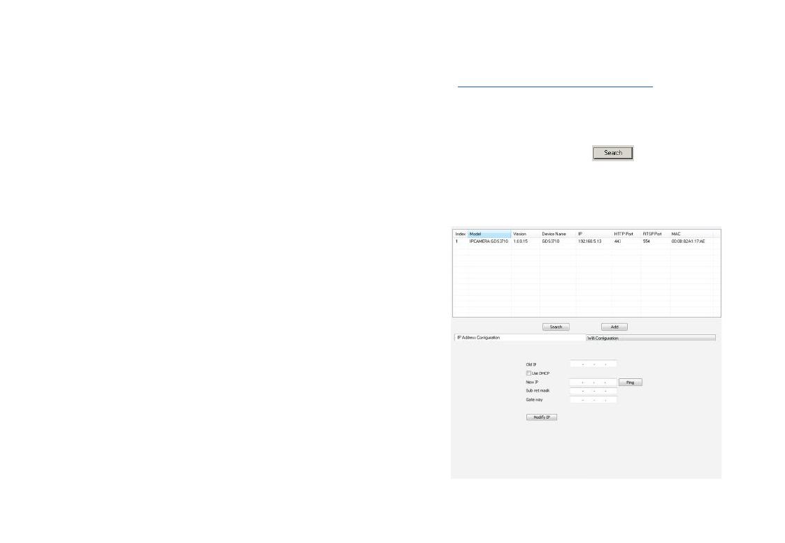
Paso 3: Haga clic en el botón para iniciar la
detección de dispositivos.
Paso 4: Los dispositivos detectados aparecerán en el campo
de salida de la siguiente manera.
~27~ ~28~
Paso 5: Abra el navegador web y escriba la dirección IP mostra-
da de GDS3710 con https: // para acceder a la GUI web. (Por ra-
zones de seguridad, el acceso web predeterminado De GDS3710
está usando HTTPS y el puerto 443).
Paso 6: Introduzca el nombre de usuario y la contraseña para
iniciar sesión. (El nombre de usuario de administrador prede-
terminado es “admin” y la contraseña aleatoria predetermi-
nada puede ser encontrada en la etiqueta del GDS3710).
Nota: Por razones de seguridad, asegúrese de cambiar la con-
traseña de administrador predeterminada en Conguración del
sistema> Gestión de usuarios.
Paso 8: Para ver el vídeo, acceda a LiveView. El navegador
indicara que es necesario activar el Active-X o Plug-in de Vídeo.
Siga las instrucciones mostradas para descargar e instalarlo.
Haga clic en el botón “Reproducir” para ver el video seleccio-
nado.
A continuación se muestra un ejemplo de captura de pantalla
con la instalación exitosa usando Active-X o Plug-in de Vídeo.
Consulte la documentación en linea y preguntas frecuen-
tes para información mas detallada.
Paso 7: Después de iniciar sesión en la webGUI, haga clic en
el menú del lado izquierdo de la interfaz web para obtener una
conguración más detallada y avanzada. http://www.grandstream.com/our-products
~29~ ~30~
GDS3710 Tabla de cableado
Nota:
1) Alimentación PoE_SP1, PoE_SP2 en DC, el rango de voltaje es
48V~57V, sin polaridad.
2) Alimentación PoE con el cableado:
PoE_SP1, marrón y marrón / blanco de unión
PoE_SP2, azul y azul/blanco de unión
3) Alimentación DC puede ser originada correctamente usando un
inyector PoE cualicado.
Conector PIN Señal Función
J2
(Básico)
3.81mm
1TX+ (Naranja/Blanco)
Ethernet,
PoE 802.3af Clase 3.
12.95W
2TX- (Naranja)
3 RX+ (Verde/ Blanco)
4 RX- (Verde)
5PoE_SP2 (Azul + Azul/
Blanco)
6PoE_SP1 (Marron + Mar-
ron/ Blanco)
7 RS485_B RS485
8 RS485_A
9 GND Fuente de Alimentación
10 12V
J3
(
Avanzado
)
3.81mm
1 GND Alarma GND
2 ALARM1_IN+
Alarma de entrada
3 ALARM1_IN-
4 ALARM2_IN+
5 ALARM2_IN-
6 NO1 Alarma de salida
7 COM1
8 NO2
Cerradura Eléctrica9 COM2
10 NC2
J4
(Especial)
2.0mm
1 GND (Negro) Alimentación
GND
Wie-
gand
2WG_D1_OUT (Naranja) Señal de salida Wiegand
3 WG_D0_OUT (Marron)
4 LED (Azul) LED indicador para señal
de salida Wiegand
5 WG_D1_IN (Blanco) Señal de entrada Wie-
gand
6 WG_D0_IN (Verde)
7 BEEP (Amarillo) Señal de pitido de salida
Wiegand
85V (Rojo) Potencia de salida Wie-
gand
Para obtener más detalles sobre el cableado GDS3710, Consulte
el Manual del usuario.
~31~ ~32~
PRECAUTIONS
CONTENU DU PACK
• Ne pas tenter d’ouvrir, de désassembler, ou de modier le
dispositif
• Suivez strictement l’exigence de la source d’alimentation
• N’exposez pas cet appareil à des températures situées hors
de la plage de -30 °C à 60 ° en opération et -35 °C à 60 ° en
stockage.
• N’exposez pas cet appareil à des environments hors de la
plage d’humidité: 10-90% RH (sans condensation)
• Veuillez suivre strictement les instructions d’installation ou
faites appel à des professionels pour installer correctement
1 x GDS3710
1 x Guide d’installation rapide
1 x Licence GPL
1 x Cadre de
Montage
1 x Cartes RFID
1 x Porte-clés RFID
4 x Joints en
caoutchouc 6 x Vis de Support
et Chevilles
6 x Vis du panneau
arrière
4 x Vis
anti-effraction 1 x Clé hexagonale
anti-effraction
1 x Modèle de
perçage
1 x Cable
Wiegand
1 x Couvercle arrière
MONTAGE DU GDS3710
Etape 2:
Tirez le câble Cat5e ou Cat6 (non inclus) à travers le joint en caou-
tchouc en sélectionnant la taille idéale et la partie protectrice de
la face arrière, veuillez vous référer au « TABLEAU DE CONNEXION
DU GDS3710 » à la n de ce guide d’installation pour les connex-
ions des broches.
Etape 1:
Consultez le « Modèle de perçage » pour percer des trous à
l’endroit ciblé sur le mur puis monter le support d’installation avec
les quatre vis et ancrages fournis (tournevis non fourni). Connectez
et serrez le l de la masse (si disponible) sur le support marqué avec
une icône de la terre imprimée.
Montage mural (en surface)
Remarque:
il est recommandé d’utiliser une pince univer-
selle et un tournevis plat de 2,5 mm (non inclus).
Ne laissez pas le l métallique non protégé à l’extérieur des
bornes après avoir enlevé la protection en plastique des ls.
FR
1 x Cap de
Protection
1 x Chiffon de
Nettoyage de la
caméra
~33~ ~34~
Etape 3:
Assurez-vous que le couvercle arrière est en place, le câblage du
panneau de couverture arrière est bon. Assemblez la pièce du
panneau de couverture arrière avec le couvercle arrière, serrez-
les à l’aide des vis fournies.
Etape 4:
Retirez les deux vis d’anti-sabotage préinstallés à l’aide de la clé hex-
agonale fournie. Alignez le GDS3710 avec le sup-
port en métal sur le mur, pressez soigneusement et tirez
le GDS3710 jusqu’à la bonne position.
Etape 5:
Installez les deux vis de sécurité arrière à l’aide de la clé hexago-
nale fournie (ne pas trop serrer les vis). Couvrez les deux trous sur
le fond du “couverlce arrière” en utilisant les deux bouchons en
silicone fournis. Vériez si tout est en ordre et terminez l’installation.
Montrage Encastrement Mural
Veuillez consulter le “Kit d’Encastrement Mural” qui peut être
acheté séparément de Grandstream.
CONNECTER LE GDS3710
Veuillez se référer à l’illustration ci-dessous et suivez les instructions
sur la page suivante.
Remarque:
Choisir l’Option A si vous utilisez un switch PoE (classe 3) ;
Ou : Option B si vous utilisez une source d’alimentation tierce.
Option B:
Adaptateur d’alimentation
à une prise électrique DC12V, 1A
mínimum (non fourni)
Option A:
Câble Ethernet RJ45 à un switch avec port Ethernet pré-alimenté
(PoE)(Classe 3) .
Port Réseau Port
d’allimentation
12V
Eteindre le GDS3710 en manipulant les câbles ou lors de
l’insertion/retrait de la pièce du couvercle arrière.
(4) KM2*5mm
~35~ ~36~
Option A
Branchez un câble Ethernet RJ45 au port réseau du GDS3710 et
branchez l’autre extrémité à un switch avec port Ethernet pré-
alimenté (PoE) (Classe 3).
Option B
Etape 1:
Sélectionnez une source d’alimentation externe DC12V,1A mini-
male (non fourni). Câblez correctement le « +,- » de l’alimentation
au connecteur de la prise du GDS3710 « 12V, GND » (se référer à
la page précédente du montage pour les instructions). Connectez
la source d’alimentation.
Etape 2:
Branchez un câble Ethernet RJ45 sur un switch réseau /concentra-
teur ou routeur.
Remarque:
Veuillez se référer à l’étape 2 du “Montage du GDS3710” pour plus
d’information sur le câblage et le branchement.
CONFIGURATION DU GDS3710
Le GDS3710 est par défaut conguré pour obtenir une adresse IP
du serveur DHCP, où se trouve l’unité.
An de savoir quelle adresse IP est attribuée à votre GDS3710,
veuillez utiliser l’outil GS_Search tel qu’illustré dans les étapes sui-
vantes.
Remarque:
Si aucun serveur DHCP n’est disponible, l’adresse IP du GDS3710
est 192.168.1.168 (après un délai de 5 minutes sans réponse du
serveur).
Etape 1: Téléchargez et installez l’outil GS_Search:
http://www.grandstream.com/support/tools
Etape 2: Exécutez l’outil de Grandstream GS_Search sur un
ordinateur connecté au même réseau/DHCP serveur.
Etape 3: Appuyez sur le button pour commencer la
détection de l’appareil.
Etape 4: Les appareils détectés seront afchés dans les
champs de résultats comme ci-dessous.
  • Page 1 1
  • Page 2 2
  • Page 3 3
  • Page 4 4
  • Page 5 5
  • Page 6 6
  • Page 7 7
  • Page 8 8
  • Page 9 9
  • Page 10 10
  • Page 11 11
  • Page 12 12
  • Page 13 13
  • Page 14 14
  • Page 15 15
  • Page 16 16
  • Page 17 17
  • Page 18 18
  • Page 19 19
  • Page 20 20
  • Page 21 21
  • Page 22 22

Grandstream GDS3710V2 インストールガイド

タイプ
インストールガイド

Grandstream GDS3710V2 は、高画質の IP ビデオ ドア システムで、ビジネスや住宅のセキュリティを強化するために必要な機能を備えています。1080p フル HD カメラと広角レンズを搭載し、昼夜を問わず鮮明な映像をキャプチャできます。また、赤外線 LED とモーション センサーも内蔵されているため、暗闇や人の動きを検知したときにアラートを発信することができます。

GDS3710V2 は、使いやすい Web インターフェイスを備えており、どこからでもリモートでアクセスしてドアのロックやロック解除、ライブ映像の視聴、録画の再生を行うことができます。また、スマートフォンやタブレットにアプリをインストールして、携帯端末からドアを制御することも可能です。

GDS3710V2 は、セキュリティを強化したいあらゆる場所の最適なソリューションです。オフィス、店舗、アパート、一軒家など、