
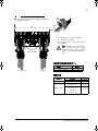
ACS850
Quick Installation Guide
ACS850-04 Drive Modules (55…160 kW, 75…200 hp)
English. . . . . . . . . . . . . . . . . . . . . 3
中文 . . . . . . . . . . . . . . . . . . . . . . . 9
3ABD0000045488 Rev A
Effective: 2012-01-20
Based on:3AUA0000045488 Rev D
2012 ABB Oy. All rights reserved.
ACS850-04_E0_E_quickguide.book Page 1 Tuesday, February 21, 2012 10:41 AM

ACS850-04_E0_E_quickguide.book Page 2 Tuesday, February 21, 2012 10:41 AM

Quick installation guide – ACS850-04
3
Quick installation guide –
ACS850-04
About this guide
This guide contains the very basic information
about the mechanical and electrical installation
of the ACS850-04 drive module (55 to 160 kW).
For complete documentation see ACS850-04
Drive Modules (55…160 kW, 75…200 hp)
Hardware Manual (code: 3AUA0000045487
[English]).
Safety instructions
WARNING! All electrical installation
and maintenance work on the drive
must be carried out by qualified
electricians only.
Never work on the drive, the braking chopper
circuit, the motor cable or the motor when input
power is applied to the drive. Always ensure by
measuring that no voltage is actually present.
A rotating permanent magnet motor can
generate a dangerous voltage. Lock the motor
shaft mechanically before connecting a
permanent magnet motor to the drive, and
before doing any work on a drive system
connected to a permanent magnet motor.
Mechanical installation
WARNING! If the drive is to be
connected to an IT power system
(i.e. ungrounded, or high-resistance-
grounded [over 30 ohms] power
system), the internal EMC filtering of
the drive must be disconnected. This should be
done before the drive is mechanically installed.
Refer to the Hardware Manual for detailed
instructions.
Fasten the drive module onto the wall with four
screws.
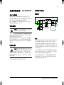
Installing the power cables
Connection diagram
Notes:
– Do not use a non-shielded or asymmetrically-
constructed motor cable. It is recommended to
use a shielded cable also as an supply (input)
cable.
– If shielded supply (input) cable is used, and
the conductivity of the shield is less than 50%
of the conductivity of a phase conductor, use a
cable with a ground conductor (1) or a separate
PE cable (2).
– For motor cabling, use a separate ground
cable (3) if the conductivity of the cable shield
is less than 50% of the conductivity of a phase
conductor and the cable has no symmetrical
ground conductors.
If there is a symmetrically-constructed ground
conductor in the motor cable in addition to the
conductive shield, connect it to the ground
connectors at both the drive and motor ends.
INPUT OUTPUT
U1
V1
W1
3
~
Motor
U1
1)
UDC+
R+
UDC
-
R
-
L1 L2 L3
(PE) (PE)PE
2)
3)
PE
Optional
braking resistor
(360°
grounding
required)
ACS850-04
V1 W1 U2 V2 W2
PE
ACS850-04_E0_E_quickguide.book Page 3 Tuesday, February 21, 2012 10:41 AM

Quick installation guide – ACS850-04
4
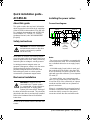
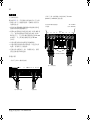
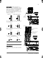
Connection procedure
Cabling examples are presented below.
Tightening torques are presented on page 5
and at appropriate points in the text.
• Remove the plastic shroud covering the main
terminals. Lift up with a screw driver from the
corner.
• Connect the twisted shields of the power
cables and separate grounding conductors to
the grounding terminals of the drive module.
• Connect the phase conductors of the supply
cable to the U1, V1 and W1 terminals, and
the phase conductors of the motor cable to
the U2, V2 and W2 terminals. The
recommended stripping length is 16 mm
(0.63”) for frame size E0 and 28 mm (1.1”)
for frame size E.
• Secure the cables mechanically outside the
drive module.
• Cut holes for the installed cables into the
clear plastic shroud to accommodate the
power cables. Press the shroud onto the
terminals.
• Connect the other ends of the power cables.
To ensure safety, pay special attention to
connection of the grounding conductors.
Cabling examples
U2
V2
W2
PE
UDC
-
R+
UDC+
R-
V1
U1
W1
PE
Input power cable Motor cable
Frame size E0: Screw terminal installation
Frame size E: Cable lug installation (16 to 70 mm
2
[AWG6 to AWG2/0] cables)
U1
V1
W1
U2
V2
W2
R-
UDC+
R+
UDC-
PE
8 N·m (5.9 lbf·ft)
Insulate the ends of the
cable lugs with tape or
shrink tube
30…44 N·m
(22…32 lbf·ft)
Input power cable Motor cable
ACS850-04_E0_E_quickguide.book Page 4 Tuesday, February 21, 2012 10:41 AM

Quick installation guide – ACS850-04
5
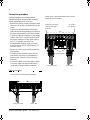
Wire sizes accepted by power
terminals
Tightening torques
PE
8 N·m (5.9 lbf·ft)
Frame size E: Screw terminal installation (95 to
240 mm
2
[AWG3/0 to 500MCM] cables)
Input power cable
Motor cable
U1 V1 W1 U2 V2 W2R-
UDC+
R+ UDC-
Drive type ACS850-04… Wire size
-103A-5, -144A-5 6 … 70 mm
2
-166A-5…-290A-5 95 … 240 mm
2
Drive type
ACS850-04…
Power terminals PE
N·m (lbf·ft) N·m (lbf·ft)
-103A-5, -144A-5 15 (11) 15 (11)
-166A-5…-290A-5
Cable lug installation
30…44 (22…32)
8 (5.9)
Allen screw
20…40 (15…30)
Screw terminal installation
30…44 (22…32)
8 (5.9)
a
b
a. Connect the cable to the terminal. Tighten the
Allen screw to 20…40 N·m (15…30 lbf·ft).
b. Connect the terminal to the drive. Tighten to
30…44 N·m (22…32 lbf·ft).
WARNING! If the wire size is less than
95 mm
2
(3/0 AWG), a crimp lug must
be used. A cable of wire size less than
95 mm
2
(3/0 AWG) connected to this
terminal will loosen and may damage
the drive.
ACS850-04_E0_E_quickguide.book Page 5 Tuesday, February 21, 2012 10:41 AM

Quick installation guide – ACS850-04
6
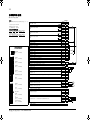
Installing the control cables
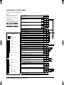
Default I/O connection diagram
XPOW
External power input
24 V DC, 1.6 A
+24VI 1
GND 2
XRO1, XRO2, XRO3
Relay output RO1 [Ready]
250 V AC / 30 V DC
2 A
NO 1
COM 2
NC 3
Relay output RO2 [Modulating]
250 V AC / 30 V DC
2 A
NO 4
COM 5
NC 6
Relay output RO3 [Fault(-1)]
250 V AC / 30 V DC
2 A
NO 7
COM 8
NC 9
XD24
+24 V DC* +24VD 1
Digital input ground DIGND 2
+24 V DC* +24VD 3
Digital input/output ground DIOGND 4
Ground selection jumper AI1
XDI
Digital input DI1 [Stop/Start] DI1 1
Digital input DI2 DI2 2
Digital input DI3 [Reset] DI3 3
Digital input DI4 DI4 4
Digital input DI5 DI5 5
Digital input DI6 or thermistor input DI6 6
Start interlock (0 = Stop) DIIL A
XDIO
Digital input/output DIO1 [Output: Ready] DIO1 1
Digital input/output DIO2 [Output: Running] DIO2 2
XAI
Reference voltage (+) +VREF 1
Reference voltage (–) -VREF 2
Ground AGND 3
Analog input AI1 (Current or voltage, selectable by jumper AI1) [Speed
reference 1]
AI1+ 4
AI1- 5
Analog input AI2 (Current or voltage, selectable by jumper AI2)
AI2+ 6
AI2- 7
AI1 current/voltage selection jumper AI1
AI2 current/voltage selection jumper AI2
XAO
Analog output AO1 [Current %]
AO1+ 1
AO1- 2
Analog output AO2 [Speed %]
AO2+ 3
AO2- 4
XD2D
Drive-to-drive link termination jumper T
Drive-to-drive link.
B1
A2
BGND 3
XSTO
Safe Torque Off. Both circuits must be closed for the drive to start.
OUT1 1
OUT2 2
IN1 3
IN2 4
Control panel connection
Memory unit connection
Notes:
[Default setting with ACS850 standard
control program (Factory macro).
*Total maximum current: 200 mA
The wiring shown is for demonstrative
purposes only.
For jumper settings, see text.
Wire sizes and tightening torques:
X
POW, XRO1, XRO2, XRO3, XD24:
0.5 … 2.5 mm
2
(24…12 AWG). Torque:
0.5 N·m (5 lbf·in)
XDI
, XDIO, XAI, XAO, XD2D, XSTO:
0.5 … 1.5 mm
2
(28…14 AWG). Torque:
0.3 N·m (3 lbf·in)
XPOW
(2-pole, 2.5 mm
2
)
Order of terminal headers and
jumpers
XRO1
(3-pole, 2.5 mm
2
)
XRO2
(3-pole, 2.5 mm
2
)
XRO3
(3-pole, 2.5 mm
2
)
XD24
(4-pole, 2.5 mm
2
)
XDI
(7-pole, 1.5 mm
2
)
DI/DIO grounding selection
XDIO
(2-pole, 1.5 mm
2
)
XAI
(7-pole, 1.5 mm
2
)
AI1, AI2
XAO
(4-pole, 1.5 mm
2
)
XD2D
(3-pole, 1.5 mm
2
)
XSTO (orange)
(4-pole, 1.5 mm
2
)
T
ACS850-04_E0_E_quickguide.book Page 6 Tuesday, February 21, 2012 10:41 AM

Quick installation guide – ACS850-04
7
Jumpers on the control unit: DI/DIO
grounding selector (located between XD24 and
XDI) – Determines whether the DIGND (ground
for digital inputs DI1…DI5) floats, or if it is
connected to DIOGND (ground for DI6, DIO1
and DIO2). If DIGND floats, the common of
digital inputs DI1…DI5 should be connected to
XD24:2. The common can be either GND or
V
cc
as DI1…DI5 are of the NPN/PNP type.
AI1 – Determines whether Analog input AI1 is
used as a current or voltage input.
AI2 – Determines whether Analog input AI2 is
used as a current or voltage input.
T – Drive-to-drive link termination. Must be set
to the ON position when the drive is the last unit
on the link.
Continue with drive start-up according to the
instructions in the appropriate Quick Start-up
Guide.
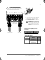
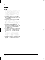
Mounting the clamp plate
The clamp plate can be fastened at the top or
the bottom of the JCU Control Unit.
Routing the control cables
1
DIGND floats DIGND tied to DIOGND
XD24
2
4
2
3
1
XD24
2
4
2
3
AI1
AI2
1
7
AI1
AI2
1
7
Current Voltage
AI1
AI2
1
7
AI1
AI2
1
7
Current Voltage
T
Termination ON Termination OFF
T
0.7 N·m
(6.2 lbf·in)
Use shrink tubing or tape
to contain strands
Remove outer jacket of cable
at clamp to expose cable
shield. Tighten to 1.5 N·m
(13 lbf·in).
ACS850-04_E0_E_quickguide.book Page 7 Tuesday, February 21, 2012 10:41 AM

Quick installation guide – ACS850-04
8
Technical data
UL checklist
• The ACS850-04 is an IP20 (UL open type)
drive to be used in a heated, indoor
controlled environment. The drive must be
installed in clean air according to enclosure
classification. Cooling air must be clean, free
from corrosive materials and electrically
conductive dust. See the Hardware Manual
for detailed specifications.
• The maximum ambient air temperature is
40 °C (104 °F) at rated current. The current
is derated for 40 to 55 °C (104 to 131 °F).
• The drive is suitable for use in a circuit
capable of delivering not more than 100,000
rms symmetrical amperes, 500 V maximum.
• The cables located within the motor circuit
must be rated for at least 75 °C (167 °F) in
UL-compliant installations.
• The input cable must be protected with fuses
or circuit breakers. Suitable IEC (class gG)
and UL (class T) fuses are listed in the
Technical data section of the Hardware
Manual. For suitable circuit breakers, contact
your local ABB representative.
• For installation in the United States, branch
circuit protection must be provided in
accordance with the National Electrical Code
(NEC) and any applicable local codes. To
fulfill this requirement, use the UL classified
fuses.
• For installation in Canada, branch circuit
protection must be provided in accordance
with Canadian Electrical Code and any
applicable provincial codes. To fulfill this
requirement, use the UL classified fuses.
• The drive provides overload protection in
accordance with the National Electrical Code
(NEC). See the appropriate Firmware
Manual for overload protection settings.
ACS850-04_E0_E_quickguide.book Page 8 Tuesday, February 21, 2012 10:41 AM

快速安装指南
– ACS850-04
9
快速安装指南 – ACS850-04
关于本指南
本指南包含了 ACS850-04 传动模块 (55 至
160 kW)机械和电气安装需遵循的基本步骤。 完
整手册请参阅 ACS850-04
传动模块
(55…160 kW, 75…200 hp)
硬件手册
( 编号:
3ABD00030508 [ 中文 ])。
安全须知
警告!只有具备资质的电气工程师才可
以对传动进行安装和维护。
不能对带电的传动、制动斩波电路、
电机电缆或电机进行任何操作。开始工作前,
要确认传动没有危险电压。
旋转的永磁电机可以产生危险电压。在永磁电
机与传动连接之前,以及在传动系统连接到永
磁电机并对其进行任何操作之前,将电机轴机
械锁死。
机械安装
警告!如果传动被连接到IT功率系统上
(也就是接地,或高电阻接地 [大于 30
ohms] 功率系统 ),必须断开内部
EMC 滤波器的连接。这项操作必须
在传动机械安装之前进行,详细信息,请参阅
硬件手册
。
用四个螺丝将传动模块紧固在墙上。
安装功率电缆
接线图
注意 :
– 不要使用无屏蔽层或非对称的电机电缆。建议
使用带屏蔽层的电缆作为供电 ( 输入 ) 电缆。
– 如果使用了带屏蔽层的电压 (输入 )电缆,且其
屏蔽层的导电率低于相导体导电率的 50%,那
么必须使用带接地导体的电缆 (1) 或使用独立的
PE 电缆 (2)。
– 对于电机布线,如果电缆屏蔽层的导电率低于
相导体导电率的 50%,并且电缆没有对称接地
导体,请使用单独的接地电缆 (3)。
除了导体屏蔽层之外,如果电机电缆还配有对
称接地导体,在传动和电机的终端将对称接地
导体连接到接地连接器上。
输入 输出
U1
V1
W1
3
~
电机
U1
1)
UDC+
R+
UDC
-
R
-
L1 L2 L3
(PE) (PE)PE
2)
3)
PE
可选制动电阻
(360° 接地要求
)
ACS850-04
V1 W1 U2 V2 W2
PE
ACS850-04_E0_E_quickguide.book Page 9 Tuesday, February 21, 2012 10:41 AM

快速安装指南
– ACS850-04
10
连接过程
下为布线示例:
请参阅第 5 页,有关紧固力矩的相应文字介绍:
• 移除主端子上的塑料盖板。用螺丝刀将其从
角落处拉出。
• 将功率电缆的螺旋盖板和独立的接地导体连
接到传动模块的接地端子。
• 将供电电缆的相导体连接到 U1, V1 和 W1 端
子上,电机电缆的相导体连接到 U2, V2 和
W2 端子上。 尺寸 E0 推荐剥线长度为16 mm
(0.63”) ,尺寸 E 推荐剥线长度为 28 mm
(1.1”)。
• 对传动模块的外部电缆进行机械保护。
• 在透明塑料盖板剪洞安装电缆,以适应功率
电缆。压紧端子上的盖板。
• 连接功率电缆的另一端。为确保安全,要特
别注意接地导体的连接。
布线示例
U2
V2
W2
PE
UDC
-
R+
UDC+
R-
V1
U1 W1
PE
输入功率电缆 电机电缆
外形尺寸
E0
:螺丝端安装
外形尺寸
E:
电缆接线头安装
(16
至
70 mm
2
[AWG6
至
AWG2/0]
的电缆
)
U1
V1
W1
U2
V2
W2
R-
UDC+
R+
UDC-
PE
8 N·m (5.9 lbf·ft)
使用胶带或收缩管使接
头绝缘。
30…44 N·m
(22…32 lbf·ft)
输入功率电缆 电机电缆
ACS850-04_E0_E_quickguide.book Page 10 Tuesday, February 21, 2012 10:41 AM

快速安装指南
– ACS850-04
11
功率端子接受的电线尺寸:
紧固力矩
PE
8 N·m (5.9 lbf·ft)
外形尺寸
E:
螺丝端安装
(95
至
240 mm
2
[AWG3/0
to 500MCM]
的电缆
)
输入功率电缆
电机电缆
U1 V1 W1 U2 V2 W2R-
UDC+
R+ UDC-
传动型号 ACS850-04… 电线尺寸
-103A-5, -144A-5 6 … 70 mm
2
-166A-5…-290A-5 95 … 240 mm
2
传动型号
ACS850-04…
功率端子 PE
N·m (lbf·ft) N·m (lbf·ft)
-103A-5, -144A-5 15 (11) 15 (11)
-166A-5…-290A-5
电缆接头安装
30…44 (22…32)
8 (5.9)
六角固定螺丝
20…40 (15…30)
螺丝端安装
30…44 (22…32)
8 (5.9)
a
b
a. 将电缆连接到端子。紧固六角固定螺丝至
20…40 N·m (15…30 lbf·ft)。
b. 将端子连接到传动单元。紧固 至 30…44 N·m
(22…32 lbf·ft)。
注意 ! 如果电线尺寸少于 95 mm
2
(3/0
AWG), 那么必须使用紧耳盖,如果连
接到该端子的电线尺寸少于 5 mm
2
(3/0
AWG),那么会发生松动或导致变频器
损坏。
ACS850-04_E0_E_quickguide.book Page 11 Tuesday, February 21, 2012 10:41 AM

快速安装指南
– ACS850-04
12
安装控制电缆
缺省 I/O 连接图
XPOW
外部电源输入
24 V DC, 1.6 A
+24VI 1
GND 2
XRO1, XRO2, XRO3
继电器输出 RO1 [ 准备 ]
250 V AC / 30 V DC
2 A
NO 1
COM 2
NC 3
继电器输出 RO2 [ 调整 ]
250 V AC / 30 V DC
2 A
NO 4
COM 5
NC 6
继电器输出 RO3 [ 故障 (-1)]
250 V AC / 30 V DC
2 A
NO 7
COM 8
NC 9
XD24
+24 V DC* +24VD 1
数字输入接地 DIGND 2
+24 V DC* +24VD 3
数字输入 / 输出接地 DIOGND 4
接地选择跳线 AI1
XDI
数字输入 DI1 [ 停止 / 启动 ]DI11
数字输入 DI2 DI2 2
数字输入 DI3 [ 重启 ]DI33
数字输入 DI4 DI4 4
数字输入 DI5 DI5 5
数字输入 DI6 或 电热器输入 DI6 6
启动互锁 (0 = 停止 ) DIIL A
XDIO
数字输入 / 输出 DIO1 [ 输出:准备 ] DIO1 1
数字输入 / 输出 DIO2 [ 输出:运行 ] DIO2 2
XAI
给定电压 (+) +VREF 1
给定电压 (–) -VREF 2
接地 AGND 3
模拟输入 AI1 ( 电流或跳线电压,选择跳线或电压,通过跳线 AI1 选择 ) [
速度给定 1]
AI1+ 4
AI1- 5
模拟输入 AI2 (
电流或电压,通过跳线 AI2 选择 )
AI2+ 6
AI2- 7
AI1 电流 / 电压选择跳线 AI1
AI2 电流 / 电压选择跳线 AI2
XAO
模拟输出 AO1 [ 电流 %]
AO1+ 1
AO1- 2
模拟输出 AO2 [ 速度 %]
AO2+ 3
AO2- 4
XD2D
传动到传动连接终止跳线 T
传动到传动连接
B1
A2
BGND 3
XSTO
安全转矩停车:传动启动时双电路都必须关闭。
OUT1 1
OUT2 2
IN1 3
IN2 4
控制盘连接
存储单元连接
注意 :
[ACS850 标准控制程序的缺省设置 ( 工厂宏
)。
* 总最大电流: 200 mA
接线图仅供演示说明。
关于跳线设置,请参见:
电线尺寸和紧固力矩:
X
POW, XRO1, XRO2, XRO3, XD24:
0.5 … 2.5 mm
2
(24…12 AWG). 转矩:
0.5 N·m (5 lbf·in)
XDI
, XDIO, XAI, XAO, XD2D, XSTO:
0.5 … 1.5 mm
2
(28…14 AWG). 转矩:
0.3 N·m (3 lbf·in)
XPOW
(2- 孔 , 2.5 mm
2
)
端子头和跳线次序
XRO1
(3- 孔 , 2.5 mm
2
)
XRO2
(3- 孔 , 2.5 mm
2
)
XRO3
(3- 孔 , 2.5 mm
2
)
XD24
(4- 孔 , 2.5 mm
2
)
XDI
(7- 孔 , 1.5 mm
2
)
DI/DIO 接地选择
XDIO
(2- 孔 , 1.5 mm
2
)
XAI
(7- 孔 , 1.5 mm
2
)
AI1, AI2
XAO
(4- 孔 , 1.5 mm
2
)
XD2D
(3- 孔 , 1.5 mm
2
)
XSTO ( 橙色 )
(4- 孔 , 1.5 mm
2
)
T
ACS850-04_E0_E_quickguide.book Page 12 Tuesday, February 21, 2012 10:41 AM

快速安装指南
– ACS850-04
13
控制单元的跳线 : DI/DIO 接地选择器 ( 位于
XD24 和 XDI) –测定是否DIGND (DI1…DI5的接
地端 ) 浮动,或者是否已连接到 DIOGND (DI6,
DIO1 和 DIO2 的接地端 )。如果 DIGND 浮动,
DI1…DI5 的公共端应该连接到 XD24:2。由于
DI1…DI5 为NPN/PNP类型,所以公共端可以为
GND 或 V
cc
中的任意一个。
AI1 – 用来选择模拟输入 AI1 的输入信号是电流
信号还是电压信号。
AI2 – 用来选择模拟输入 AI2 的输入信号是电流
信号还是电压信号。
T – 传动对传动连接的链路终端。当传动是最后
一个单元时,必须设置到 ON 位置。
关于传动的启动请参考快速启动指南中的相关
介绍。
安装电缆固定夹
电缆固定夹可以安装在 JCU 控制单元的顶部或
底部。
控制电缆布线
1
DIGND 浮动 DIGND 连接到 DIOGND
XD24
2
4
2
3
1
XD24
2
4
2
3
AI1
AI2
1
7
AI1
AI2
1
7
电流 电压
AI1
AI2
1
7
AI1
AI2
1
7
电流 电压
T
ON OFF
T
0.7 N·m
(6.2 lbf·in)
使用热缩管或胶带包住
屏蔽层
剥开电缆固定夹处的电缆外
皮,将屏蔽层裸露出来。
1.5 N·m (13 lbf·in)
ACS850-04_E0_E_quickguide.book Page 13 Tuesday, February 21, 2012 10:41 AM

快速安装指南
– ACS850-04
14
技术数据
UL 清单
• ACS850-04是IP20 (UL开路类型)防护等级的
传动,用于室内温度可控的环境中。 传动必
须安装在符合要求的清洁环境中。冷却空气
必须干净,并且没有腐蚀性气体和导电灰尘。
详细说明请参见
硬件手册。
• 在额定电流下,最高环境空气温度为 40 °C
(104 °F)。在 40至 55 °C (104 至 131 °F)温度
下,电流需要降容。
• 传动单元适用于电流有效值不超过 100,000
A,最大电压 500 V 的电路容量。
• 遵照 UL 认证的安全要求,位于电机内部的电
缆至少允许 75 °C (167 °F) 时降容使用。
• 输入电缆必须有熔断器或断路器保护。符合
IEC (gG)和UL (T)的熔断器在
硬件手册
技术数
据一章中列出。关于符合标准的断路器,请
联系当地 ABB 代表处。
• 对于美国用户,按照国家电气法规 (NEC)和任
何适用的当地法规,必须提供支路保护设备。
为了满足这一要求,请使用 UL 认证的熔断
器。
• 对于加拿大用户,按照加拿大电气法规和各
省法规的要求,必须提供支路保护设备。为
了满足这一要求,请使用 UL 认证的熔断器。
• 传动提供符合美国国家电气法规(NEC)的过载
保护功能。关于过载保护设置请参见相关
固
件手册
。
ACS850-04_E0_E_quickguide.book Page 14 Tuesday, February 21, 2012 10:41 AM

ACS850-04_E0_E_quickguide.book Page 15 Tuesday, February 21, 2012 10:41 AM

3ABD0000045488 Rev A
EFFECTIVE: 2012-02-20
Based on:3AUA0000045488 Rev D
北京 ABB 电气传动系统有限公司
中国,北京, 100015
北京市朝阳区酒仙桥北路甲 10 号 D 区 1 号
电话:010-58217788
传真:010-58217518/58217618
服务热线:(+86) 400 810 8885
网址:http://www.abb.com/drives
ACS850-04_E0_E_quickguide.book Page 16 Tuesday, February 21, 2012 10:41 AM
-
 1
1
-
 2
2
-
 3
3
-
 4
4
-
 5
5
-
 6
6
-
 7
7
-
 8
8
-
 9
9
-
 10
10
-
 11
11
-
 12
12
-
 13
13
-
 14
14
-
 15
15
-
 16
16


ABB ACS850-04 series Quick Installation Manual
- タイプ
- Quick Installation Manual
- このマニュアルも適しています
他の言語で
- English: ABB ACS850-04 series
その他のドキュメント
-
Roland R-05 取扱説明書
-
Mitsubishi Heavy Industries SC-WBGW256 インストールガイド
-
WEG CFW500 インストールガイド
-
CTEK SMARTPASS 120 取扱説明書
-
Mettler Toledo 5000TOCi Sensor 取扱説明書
-
Contec CPSN-AI-1208LI リファレンスガイド
-
Fagor CNC 8070 for other applications 取扱説明書
-
-
-
Fagor CNC 8065 for lathes 取扱説明書