
TABLE OF CONTENTS
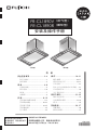
Installation/Operation Manual
FR-CL1890V (Ventilating Type)
FR-CL1890R (Recycling Type)
1F02 2281
*1F022281*
(Ventilating type) (Recycling type)
Safety Precautions ..................2~4
Caution for Maintenance ...................4
Precautions on Use ...........................4
Preparation ..............................4~8
Convenient Function ......................4, 5
Name of Parts ...............................5, 6
Specification ......................................7
Circuit Diagram .................................. 8
Installation .............................8~15
Preparation and Check
before Installation ..........................8, 9
Cooker Hood Installation ...........10~13
Fixing Duct Cover ............................14
Attaching Rectifier Panel .................15
Operation Check ..............................15
Operation .............................16~21
Switch ........................................ 16, 17
Cleaning Lamp ..........................18, 19
Timer Operation ..............................19
Idle Operation Prevention Timer ...... 19
Automatic Shutdown ........................20
About the Cleaning Time .................21
Caution for Maintenance .....22~25
Caution Matters for Maintenance ....22
Detaching Cleaned Parts ..........22~24
Cleaning ..........................................25
Other Information .................26, 27
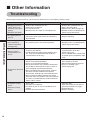
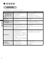
Troubleshooting ...............................26
Service and Warranty ......................27
Thank you very much for your purchase of our cooker hood.
Before installing/operating the cooker hood, please read this Manual thoroughly.
Keep this manual in a convenient place for future reference.
To the sales shop/installer:
After installation, please
give this manual to the
user without fail.

2
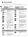
Safety Precautions
WARNING
Never attempt to disassemble,
repair or modify.
Entrust them to the qualified
technician, otherwise fire, electric
shock, or abnormal performance
may occur.
Don’t connect to the power
voltage other than 220V/230V/
240V AC.
Fire or electric shock may result in.
Electric wiring must be made
properly by the professional
installer or personnel.
Incorrect wiring may be cause of
electric leakage or fire.
Safety Precautions
Be sure to disconnect the power
plug from the wall outlet, or
switch off the breaker when
care and maintenance. Also,
don’t handle the power plug or
breaker with wet hand.
Electric shock or injury may result
in.
When dust accumulated on the
blades of the power plug or on
their roots, wipe off well.
Fire or electric shock may result in.
Mounting work should be
done by 2 persons minimum.
The weight of the cooker hood is
about 28kg (FR-CL1890V), 31kg
(FR-CL1890R).
There is a breaker incorporated
in the fixed wiring to be provided
to ensure all-pole disconnection
from the supply mains.
Make sure to follow the wiring
instructions and disconnect
all poles using equipment that
meets the Overvoltage Category
III requirements for fixed wiring.
The cooker hood is intended to
be installed over a hob with up
to four hob elements or burners,
no more than total 7.0kW.
Less than
4 burners
(7.0kW)
WARNING
CAUTION
Alerts possible risk of death or serious injury, if not observed.
Alerts possible risk of injury or physical damage, if not observed.
Read the following safety instructions before operating, and use the cooker hood properly and securely.
These instructions are for correct operation of the product to prevent any risk of hazards or damages inflicting on
you or others. The instructions are classified into 2 categories as "WARNING" and "CAUTION" depending on their
emergency and severity. Pay attention and strictly observe the instructions as they are critical for safety.
Disassembly,
repair, or
modification
prohibited
Using
prohibited
Assembly
cautioned
Mounting
cautioned
Mounting
cautioned
Mounting
cautioned
Disconnect
the plug
Wipe off
dust
Don’t spray water on the
electric parts.
Fire or electric shock may result in.
Spraying
water
prohibited
Choose a mounting location
where sufficient air flow is
maintained.
CO poisoning may result if not
ventilated adequately while using a
natural vent type stove, etc.
Do not discharge the smoke from
cooker hood into the hot chimney
duct for smoke from burning gas
or other fuels. (It is not applied
to pump gas back into the indoor
cooker hood.)
Exhaust adjustment must be
ensured.
There shall be adequate
ventilation of the room when the
cooker hood is used at Air supply
the same time as appliances
burning gas or other fuels.
There is a fire risk if cleaning is
not carried out in accordance
with the instructions.
Do not flambé under the cooker
hood.
This appliance is not intended for
use by person (including children)
with reduced physical, sensory
or mental capabilities, or lack
of experience and knowledge,
unless they have been given
supervision or instruction
concerning use of the appliance
by a person responsible for their
safety.
Children should be supervised to
ensure that they do not play with the
appliance.
When there may be a gas leak in
your gas hob, don’t switch on or
off the cooker hood.
Gas explosion may result in.
Operation
prohibited
Air supply
cautioned
Strictly
implemented
Ensure
adjustment
Supervision
requested
Air supply
cautioned
Clean
frequently
Flambé
prohibited

3
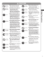
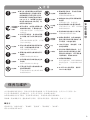
Safety Precautions
CAUTION
Be sure to disconnect the power
plug from the wall outlet, or
switch off the breaker when not
using for a long time.
Insulation may be deteriorated, and
fire or electric shock may result in.
When disconnecting the power
plug, hold the plug itself. Don’t
pull the cord anyway.
The cord may be damaged, and
fire or electric shock may result in.
Never use the product in a wet
place such as bath room, etc.
(Use a ventilation fan for bath
room.)
It may be cause of fire or failure if
used.
Disconnect
by holding
the plug
Disconnect
by holding
the plug
Using
prohibited
Ensure that electric wiring is
made safely according to the
standard or regulations related.
Incorrect wiring may result in fire or
electrical shock.
Assemble the fan or component
parts securely.
Injury by dropping may result in.
Assembly
cautioned
Assembly
cautioned
Don’t touch the disk or parts
around it while cooking.
The disk or parts may drop, and
burn or injury may result in.
Contact
prohibited
If the power cord is damaged,
it must be replaced by the
manufacturer, its service agent
or similarly qualified persons in
order to avoid a hazard.
Be sure to wear gloves when
care and maintenance.
Injury by the sharp edges or
corners may result in.
Be sure to ensure that duct is
connected to the outdoor. In
order to avoid fire and keep
fresh air, please discharge the
exhaust gas to the outdoor.
Please do not discharge the
exhaust gas into the wall, loft or
garage.
Do not put anything on the
cooker hood.
It may be cause of fire, failure, or
injury by dropping.
To avoid eye damage, do not
look directly at the LED light
while it is on.
During operation, never insert
fingers or other objects.
Failure or injury may result in.
Switch off the cooker hood at
once when oil caught fire while
cooking.
It’s dangerous if not stop as fire is
built up.
Contact
prohibited
Operation
prohibited
Prohibited
Prohibited
Replace the
cord if it’s
damaged
Wear
gloves
Strictly
implemented
The minimum distance between
the supporting surface for
the cooking vessels on the
hob and the lowest part of the
cooker hood. When the cooker
hood is located above a hob,
this distance shall be at least
750mm. If the instructions for
installation for the hob specify a
greater distance, this has to be
taken into account.
Mounting
cautioned
Mount the product securely
after selecting a solid place.
Dropping may result in injury.
The air must not be discharged
into a flue that is used for
exhausting fumes from
appliances burning gas or
other fuels (not applicable to
appliances that only discharge
the air back into the room).
When the oil level reaches 1/2
of oil tray, please timely clean
it to prevent overflow and oil
dripping during removal.from
appliances burning gas or
other fuels (not applicable to
appliances that only discharge
the air back into the room).
Mounting
cautioned
Improper
discharge
prohibited
Caution
Use attachment screws only.
If you fail to follow the instructions
provided in this manual when
installing other screws or fixed
equipment, it may cause an
electrical hazard.
Contact FUJIOH or an agent
when changing LED lamps in
this product.
Caution
Caution

4
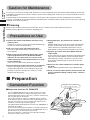
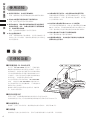
Preparation
Adopt new function OIL SMASHER
The "OIL SMASHER device unit" of this product can collect
the oils adhered inside the cooker hood and on the fan well.
Compared with the previous type, this is a kind of cooker hood
with very little greasy dirt therein.
Greasy dirt caused by cooking is collected via porous filters
in the previous type of cooker hood. The unfiltered greasy dirt
will stick to the inner part of the cooker hood and on the fan.
Therefore, it needs to be cleaned regularly.
The independently-developed new function-"OIL SMASHER" is
applied in this product.
To recycle the cooking fume and water caused by cooking into
the oil tray via the powerful function of OIL SMASHER so as to
greatly reduce the oil stain adhering to the fan.
One-touch operation is applied in oil tray/disk disassembly/
installation, and it is easy to clean.
Cooking fume, odor and water vapor
are discharged to the outdoor.
Oil and water are collected
via a disk
Collected to
the oil tray
Fan
Oil
Water
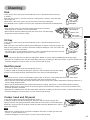
Preparation
Operate the cooker hood without fail when using
cooking wares.
Otherwise, it may be cause of the cooker hood damage
or failure by increased temperature.
Don’t use a gas range with nothing put on it.
The body of the cooker hood is heated, and it may
cause trouble.
When using with the Induction Heater (IH), smoke
capturing performance may be deteriorated by
influence of cross wind. Also, the surface of the
cooker hood may be dew condensation if it is used
in low temperature.
In this case, use the cooker hood after wiping off.
Prevent influence of direct wind from air conditioner.
Smoke capturing performance may be deteriorated
if influenced. Especially, as the Induction Heater (IH)
provides nearly no ascending air current, it is easily
influenced in open place.
During operation, pay attention to sufficient air
supply.
Provide adequate air intake slots on the wall opposite
from the cooker hood, or open the door of the room
a little. Otherwise, ventilation performance may be
deteriorated, or abnormal noise/vibration may result in.
Separate gas heater more than 500mm from the
cooker hood.
As the around of gas heater becomes high temperature,
separate more than 500mm. Never install the cooker
hood above gas heater. Otherwise, it may be cause
of the cooker hood damage or failure by increased
temperature.
Do not use the cooker hood with its rectifier panel
removed.
Smoke capturing performance may be deteriorated.
Firstly, the waste cooker hood is processed into the
status incapable of being used by others, and then,
discard it.
Safety
Precautions
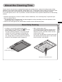
It is very easy to stain the cooker hood, therefore, be sure to frequently clean the cooker hood (especially for the disk,
it should be cleaned for one at least 2 months. For the family cooking two meals, be sure to clean the disk for once at
least one month).
If cooker hood is not cleaned for a long time, a lot of greasy dirt accumulates to form stubborn greasy hard lump.
If oil tray, surroundings of the cooker hood and rectifier panel are polluted, please timely clean it every time. (Cleaning
standard: once about 2 months)
Cleaning
The parts that require maintenance are the disk, oil tray, rectifier panel, cooker hood and oil panel.
Please refer to page 22 for instructions regarding care.
Convenient Function
Precautions on Use
Caution for Maintenance

5
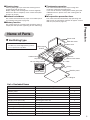
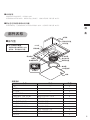
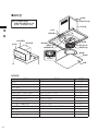
Preparation
About the disk
The disk may shake slightly during rotation,
it is not performance problem.
LED lamp
Switch
Cooker Hood
Oil panel
Oil tray fixing plate
Detach button
Power cord
Slide duct cover
Duct cover
Sensor
Direct-current motor
Disk
Oil tray
Rectifier panel
Magnet
Cleaning lamp
Cleaning lamp lights up to remind the cleaning time of
cooker hood (refer to page 18).
Display setting of the cleaning time can be changed by
reference to the use frequency of the cooker hood (refer
to pages 18 and 19).
Automatic shutdown
The cooker hood automatically stops once rectifier panel
is in opening state (refer to page 20).
Memory function
The cooker hood can save the former operation status to
simplify the next operation (operating air flow and timing).
Timekeeping operation
The cooker hood automatically stops running after
continuous running to the setting time.
If you want to clean the cooking odor and the greasy dirt
adhered to the fan, please use it after cooking (refer to
page 19).
Idle operation prevention timer
The cooker hood will automatically stop operating and
light will turn off if operation continues for approx. 5 hours
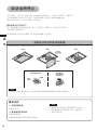
with no input. (refer to page 19).
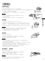
List of Included Items
Name Usage Quantity
Main unit
—
1
Rectifier panel
—
1
Duct cover
—
1
Slide duct cover
—
1
Washer-head wood screw (Ø5.1×45) Mounting hook and the duct cover 8
Hanging screw (Ø5.1×35) Mounting the main unit 2
Duct cover fixing bracket Fixing duct cover 2
Flat-head screw (M4×8) Fixing duct cover 2
Mounting screw (M4×10) Fixing duct cover 2
Exhaust port Connecting the main unit and the duct 1
Fixing screw (M4×8) Connecting the main unit and the exhaust port 4
Soft tape
—
1
Name of Parts
Ventilating type

6
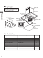
Preparation
LED lamp
Switch
Cooker Hood
Oil panel
Oil tray fixing plate
Power cord
Duct cover
Slide duct cover
Sensor
Direct-current motor
Disk
Oil tray
Rectifier panel
Magnet
Exhaust box
Exhaust adapter
Recycling device
Detach button
About the disk
The disk may shake slightly during rotation,
it is not performance problem.
List of Included Items
Name Usage Quantity
Main unit
—
1
Rectifier panel
—
1
Duct cover
—
1
Slide duct cover
—
1
Washer-head wood screw (Ø5.1×45) Mounting hook and the duct cover 8
Hanging screw (Ø5.1×35) Mounting the main unit 2
Duct cover fixing bracket Fixing duct cover 2
Flat-head screw (M4×8) Fixing duct cover 2
Mounting screw (M4×10) Fixing duct cover 2
Fixing screw (M4×8) Fixing recycling device and exhaust adapter 14
Recycling device
—
1
Exhaust adapter
—
1
Exhaust box — 1
Recycling type

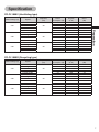
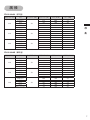
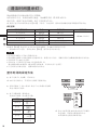
7
Preparation
Rated voltage (V) Speed
Frequency
(Hz)
Power
consumption (W)
Air Flow
(m
3
/h)
Noise
(dB)
220
Boost Mode
50
135 600 53
High 62 420 46
Medium 48 380 44
Low 30 300 38
24 hour mode 20 250 32
230
Boost Mode
50
135 600 53
High 62 420 46
Medium 48 380 44
Low 30 300 38
24 hour mode 20 250 32
240
Boost Mode
50
135 600 53
High 62 420 46
Medium 48 380 44
Low 30 300 38
24 hour mode 20 250 32
Rated voltage (V) Speed
Frequency
(Hz)
Power
consumption (W)
Air Flow
(m
3
/h)
Noise
(dB)
220
Boost Mode
50
140 520 57
High 94 420 54
Medium 69 380 51
Low 39 300 44
24 hour mode 25 250 40
230
Boost Mode
50
150 535 57
High 94 420 54
Medium 69 380 51
Low 39 300 44
24 hour mode 25 250 40
240
Boost Mode
50
160 550 57
High 94 420 54
Medium 69 380 51
Low 39 300 44
24 hour mode 25 250 40
FR-CL1890V (Ventilating type)
FR-CL1890R (Recycling type)
Specification

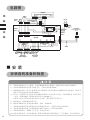
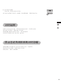
8
Installation
1. Mount the cooker hood carefully and avoid contact with any metal parts (the lath in the wall or the like) of the
building.
2. Never embed the body of the cooker hood in the wall. Otherwise, leakage current in the wall, if any, flows to the
body of the cooker hood.
3. The air must not be discharged into a flue that is used for exhausting fumes from appliances burning gas or
other fuels (not applicable to appliances that only discharge the air back into the room).
4. The minimum distance between the supporting surface for the cooking vessels on the hob and the lowest part
of the cooker hood. When the cooker hood is located above a hob, this distance shall be at least 750mm.
If the instructions for installation for the hob specify a greater distance, this has to be taken into account.
5. Use a gas range having a narrower width than that of the cooker hood.
6. Avoid using the cooker hood with changes in the specification, for instance, with modifying the switch.
7. Do not install the cooker hood in a wet area or in other wet rooms since it may result in electric shock or
damage.
8. Do not install the cooker hood at a place where its ambient temperature exceeds 40°C, otherwise it may result
in failure.
9. To protect your hands from injury, wear working gloves when installing the cooker hood.
10. If the power cord is damaged, it must be replaced by the manufacturer or its service agent or a similarly
qualified person in order to avoid a hazard.
CAUTION
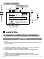
220V/230V/240V
50 Hz
(3P)
(3P)
(6P)
(6P)
(3P)
(2P)
(4P)
(4P)
(4P) (9P)
(4P)
Connector
Black
Blue
Yellow
Red
Pink
Grey
Connector
Connector
Switch board
Black
Black
Operation
On/off
Air
flow
Timer Light
Cleaning
lamp
24 hour
mode
Connector
Grey
Orange
Brown
Black
Blue
Yellow
Red
Connect to the
light board
(remote control
light area)
Connector
Control board
The 1st side
Direct-current motor
(use for fan)
Direct-current motor
(use for disk)
Connector
Connector
Connector
Red Red
Red
White
White
Green / Yellow
White
LED power
supply
Red
Wiring box
Rod terminal
Black
Black
Blue
Green
White
Green
Black
ConnectorConnector
Connector
Black
Green
White
Yellow
Yellow
Red
Red
Blue
Blue
Orange
Brown
Yellow
White
Black
Red
Orange
Brown
Yellow
White
Black
Pink
Red
The 2nd side
Transformer
Green / Yellow
LED light
Preparation
Circuit Diagram
Preparation and Check before Installation
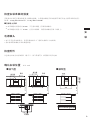
Installation

9
Installation
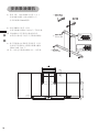
900
Ľ750
550『960
Ľ750
550『960
122
53
900
Duct
Duct
External view
Suspended ceiling
Suspended ceiling
900
Suspended ceiling
A
FR-CL18-DCT85 800~850
FR-CL18-DCT90 850~900
Ľ750
A
750『800
(Standard type)
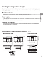
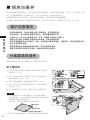
Checking mounting surface strength
The mounting surface should have sufficient strength enough to support the cooker hood. Mount the cooker
hood on a place durable to support the weight of the cooker hood. (Product weight: 28.0kg (FR-CL1890V),
31.0kg (FR-CL1890R).
Install it on the wall
• If the thickness is more than 20mm, mount the cooker hood directly to the wall.
• If the thickness is less than 20mm, embed a reinforcing board and mount the cooker hood to this board.
Power supply
• The product does not include the power plug. Please have a qualified technician attach a power plug to
the power cord.
• Be sure to use the wall outlet only for the cooker hood.
Checking the accessory
Take out the main unit and accessory parts (exhaust port, duct cover and so on) from the packing box,
and check whether there is any shortage.
(Unit: mm)
Confirmation of the installation location
Recycling type
Ventilating type

10
Installation
5mm
Washer-head
wood screw
(Ø5.1×45)
Hanging screw
(Ø5.1×35)
Washer-head
wood screw
(Ø5.1×45)
Duct cover
fixing bracket
8.5~9.5mm
465
24
30
1520
840
300
360
383
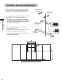
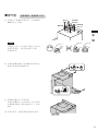
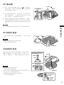
1) Refer to the figure below, insert two washer-
head wood screws (Ø5.1×45) in the bolt hole
position (
) 5mm distance into the wall.
2) Insert two hanging screw (Ø5.1×35) in the bolt
hole position (
) and screw it firmly.
* Hanging screw is screwed into the degree
incapable of being embedded into the wall. If
the screw is embedded into the wall, cooker
hood can be not installed.
3) Duct cover fixing bracket and the fittings
mounting position (
).
Insert two duct cover fixing brackets and two
washer-head wood screws (Ø5.1×45).
* Please note to align at the center of cooker
hood during installation.
Cooker Hood Installation

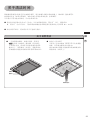
11
Installation
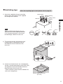
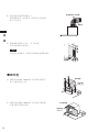
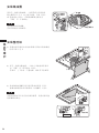
2) The mounted washer-head wood screw/
hanging screw is respectively hung in
the fixed bolt hole on the back of the
main unit.
Washer-head wood screw
(Ø5.1×45)
3) washer-head wood screws are screwed down,
and the 2 washer-head wood screws (Ø5.1×45)
are tightened in the two Ø9 holes below the
fixed bolt hole to fix the main unit.
* After installation, please confirm whether the
main unit is hung firmly.
Shutter opening
direction
Soft tape
Exhaust port
Fixing scre
ws
(M4×8)
Ventilating type
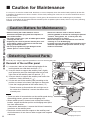
1) Attach the supplied soft tape around the
exhaust port, then secure it with supplied
four fixing screws (M4×8).
When the recycling type is used, please refer to page 12.
Note
When attaching the exhaust port, pay
attention to its shutter opening direction.
If it's installed incorrectly, it may cause
bad discharge, abnormal noise, etc.
Correct
Wrong

12
Installation
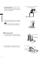
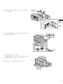
Recycling type
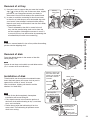
1) The recycling device is mounted above the
top of the main unit via 4 fixing screws (M4×8).
Recycling device
Fixing screw
(M4×8)
Fixing screw
(M4×8)
Exhaust adapter
2) Exhaust adapter is mounted in front of the
recycling device via 4 fixing screws (M4×8).
Flexible tube
duct
Taping with non-flammable materials
(Aluminum tape etc.)
4) Connect Ø150 flexible tube duct or the like
with the exhaust port.
Make the exhaust port secure and air-tight
using non-flammable tape such as aluminum
tape, etc. (not supplied)
15
80
90
70
5) Please ensure that breaker is in "off" position,
and then, plug power supply into the socket.
Note
When you connect power plugs, please be
sure to turn off the breaker of switchboard.

13
Installation
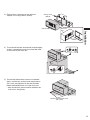
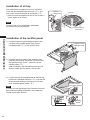
3) Exhaust box is mounted on the exhaust
adapter via 6 fixing screws (M4×8).
Fixing screw
(M4×8)
Exhaust box
Exhaust
box
4) The mounted washer-head wood screw/hanging
screw is respectively hung in the fixed bolt hole
on the back of the main unit.
5) Two washer-head wood screws are screwed
down, and the two washer-head wood screws
(Ø5.1×45) are tightened in the two Ø9 holes
below the fixed bolt hole to fix the main unit.
* After installation, please confirm whether the
main unit is hung firmly.
Washer-head wood screw
(Ø5.1×45)

14
Installation
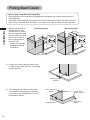
Mounting screw
(M4×10)
Flat-head screw
(M4×8)
Flat-head screw
(M4×8)
Duct cover
fixing bracket
Slide duct cover
1) Slide the duct cover to
shelter the main unit,
and the duct (2 sites at
left and right) downside
the rear end of the duct
cover that is hung on
the hanging screw of
the main unit.
* Note to not damage
the product during
installation.
2) Lower part in front side of the duct cover
is fixed on the cooker hood via 2 mounting
screws (M4×10).
3) The sliding potion inside the duct cover
is stretched to the ceiling part and fixed
on the duct cover fixing bracket via 2 flat-
head screws (M4×8).
Duct cover
Loophole
Hanging
screw
Duct cover
Loophole
Hanging
screw
(Ventilating type) (Recycling type)
Fixing Duct Cover
* When using a slide duct sold separately
Please dispose of the slide duct packaged with the product and use the slide duct that is
sold separately.
Please be sure to keep the mounting screws and attachment bracket for the duct cover that
were used for the slide duct removed as you need to use them to attach the new slide duct.

15
Installation
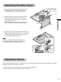
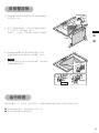
Switch the switchboard to the "on" position for test run. How to operate the switches and confirm the running
condition, please refer to pages 16 and 17.
• Check that the fan rotates normally at all speeds during operation.
• Check that there are no abnormal sound or vibration.
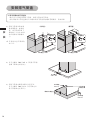
1) Hang the Left and right hooking bracket in the
rear end of the rectifier panel firmly on the
hanging bracket (
) of the cooker hood.
2) Use both hands to support the rectifier panel,
hold the front-end up and insert it until you
hear the locking sound, “crack” , and then, fix
the rectifier panel (
).
After installation, pull the rectifier panel up and
down to check that the panel is firmly fixed.
Hanging bracket
Hooking bracket
Close
3) Loosen the bolt of braking buckle till the braking
buckle can slide back and forth (
) to make the
braking buckle sliding to the bottom of the rear
end, and then tighten screw (
).
Confirm whether
it has been locked
Braking
buckle
Tight Make it sliding
Note
In order to avoid the falling of the fixed parts
caused by insufficient locking, please be sure
to keep the rectifier panel solid and firm.
Attaching Rectifier Panel
Operation Check

16
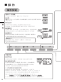
Operation
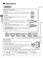
Air flow switch
• Regulate air flow
Under running condition, after press the switch, switch the air flow (corresponding
green light turns on).
• Operation in boost mode
Under running condition, continue to press the air flow switch (about 2 seconds)
to switch into boost mode. After changing into boost mode, carry out the timing
operation for 5 minutes via the high air flow which is more than "High" air flow, and
5 minutes later, get back to the preset air flow for operation.
* Timer settings on the status of boost mode
Under the status of boost mode, if press the timer switch, time is set "3 minutes", the boost mode is end after 3
minutes and the cooker hood stops running. If it is set as "15 minutes" or "30 minutes", after running 5 minutes
at boost mode, return to the air flow before switching the boost mode for operation in remaining time.
E.g.) when it switches into boost mode from the "low" air flow and timer is set as "15 minutes",
Boost mode
➝
(after 5 minutes) running at the "Low" air flow
➝
(after 10min) shutdown
*
If you want to finish the boost mode, press the air flow switch to switch into other volume or stop running via
pressing operation on/off switch.
Operation
Operation on/off switch
* When fan is in shutdown status, LED indicator turns on (standby).
• Operation
When LED indicator turns on, after pressing the switch, the cooker hood goes
into operation according to the air flow at the former shutdown time (orange light
turns off).
• Shut down
During running condition, after pressing the switch, the cooker hood will
immediately stops running.
When it is set as 24 hour mode, switch to 24 hour mode for running
(orange light turns off).
• Switch lock
Continue to press the switch (about 3 seconds), close all operating
functions to lock the operation switch. When it is in lock state, the
on/off light and the 15 minutes-timer display lamp flicker alternatively.
• Release lock
When it is in lock state, continue to press the switch (about 3
seconds) to release lock and return to normal.
*
After unlocking, please operate the various functions again
according to requirements.
Under lock-out state
Press the switch to make the "bleeping" warn, and the air flow light flashes.
Reject the indication of the operation switch.
Continue
to press
(about 3 sec.)
Beeps
Beeps
Continue
to press
(about 3 sec.)
Ɵ
Ɵ
[
High
]
[
Medium
]
[
Low
]
Switch

17
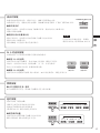
Operation
Lamp switch
• LED lamp turns on/off
Press the switch and the LED lamp lights on. It turns on/off repeatedly every time press the switch.
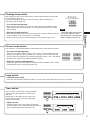
Timer switch
Press the timer switch under running condition,
switch into the timing operation at the former
stop time.
Setting time is changed every time press the
switch (refer to page 19) (the corresponding
orange lamp flashes)
• Adjust volume
Continue to press the switch (about 3 seconds)
under shutdown state, switch the operation volume
(the corresponding orange lamp turns on).
[
3 minutes
] [15
minutes
][
30 minutes
][
None
]
[
Loud
] [
Standard
][
None
]
24 hour mode switch
This function is a continued operation mode with lower air flow than low speed’s.
• Set 24 hour mode operation
After press the switch under shutdown state, set it as 24 hour mode operation
(orange lamp lights on). During setting, it is running in lower air flow than low
speed's under the shutdown state (after the operation switch is "off", after timing
operation and after prevent forgetting off-delay timing).
• Relief the 24 hour mode operation
Continue to press the switch (about 3 seconds) under shutdown state, 24 hour
mode operation stops (orange lamp goes out).
24 hour mode
settings ”ON”
24 hour mode
settings ”OFF”
Cleaning lamp switch
After being up to the preset cleaning time, cleaning lamp displays and reminds
the time (refer to page 18).
If cleaning lamp lights up, please clean the oil tray, disk and other parts
("cleaning" (refer to page 25)).
• Turn off the cleaning lamp
When cleaning lamp lights up, after press the switch under shutdown state,
the lamp goes out, and cleaning time is re-clocked. Please press the switch
after cleaning.
• Re-clock the cleaning time
When cleaning lamp goes out, continue to press the switch (about 3 seconds)
under shutdown state, cleaning time is re-clocked.
Please carry out it after cleaning and before warning (before lamp is on).
When it is up to
the cleaning time,
the display lamp lights up
Note
If the lamp lights on too early
or too late, please modify
the settings of cleaning time
(refer to pages 18 and 19).

18
Operation
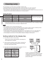
The cleaning time of cooker hood is reminded via display lamp.
If cleaning lamp lights up, please clean the disk, oil tray and other parts (refer to page 25).
After cleaning, press the cleaning lamp switch and the lamp goes out (refer to page 17).
* Initial setting of the cleaning lamp display time is [standard], change the settings in conformity with the use
frequency of the cooker hood by reference to the "setting standard".
Setting Standard
Daily using time Settings Setting time Time for light on
Around 1-hour Shortest 60-hour
Light up in around 60 days
Around 1.5-hour Short 90-hour
Around 2-hour Standard 120-hour
Around 3-hour Long 180-hour
— Removing Cleaning lamp function relieved Don't light it up
E.g.) according to the [standard], about 1 hour is set for running the cooker hood, and about 120 days later,
the cleaning lamp lights on. If you want to light on the lamp about 60 days later, the setting is changed
into the [shortest] to make it turning on at appropriate time.
Setting method for the display time
1) Press the on/off switch to stop running.
* Under 24 hour mode running condition, the settings can
be changed without shutdown.
2) At the same time, continue to press (about 3 seconds) the
on/off switch and the cleaning lamp switch, the cleaning
lamp under setting mode flashes.
3) Press the air flow switch and change the settings. Press the
switch every time, the setting will be switched.
Settings
The display light
Shortest
Short
Standard
Long
None
At the same time,
continue to press it
(about 3s)
The shortest
Short
Standard
Long
Removing
Note
After resetting, restart to count the cleaning time.
For the power plug of the cooker hood, keep timing since socket is pulled up. When re-clocking is done,
please operate the cleaning lamp switch or change the settings of cleaning time.
Running time does not contain 24 hour mode operation.
Under running condition (only illuminating lamp turns on and excepting for 24 hour mode operation),
cut off the power via wall button/power plug/breaker, etc., there exists error in the recorded time.
If the lamp lights on too early or too late, please modify the settings of cleaning time.
* If there is no operation for 10sec under
setting mode continuously, cancel the setting
and get back to the status before changing
the settings. If setting needs to be changed,
please reset again.
Cleaning Lamp

19
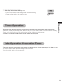
Operation
Setting the timer operation during the running state, the cooker hood automatically stops running after
continuous running to the setting time. When it is set as 24 hour mode, switch to 24 hour mode for running.
Please use it after cooking, as the cooking odor shall be collected and discharged.
3 minutes, 15 minutes and 30 minutes may be chosen for timing time.
The cooker hood will automatically stop running and lighting will turn off after operating for 5h. When it is set
as 24 hour mode, switch operation setting to 24 hour mode.
Press the switch again to restart operation.
4) Press the cleaning lamp switch.
After setup, start to count cleaning time.
* If press on/off switch under setting mode, cancel the setting
change and get back to the original status.
Idle Operation Prevention Timer
Timer Operation

20
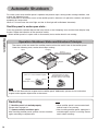
Operation
For safety sake, when rectifier panel is opened, the product stops running under running condition, and
makes the "bleeping" warn.
And furthermore, if installation status of the rectifier panel is abnormal, all operation switches are locked
excepting for lamp switch.
When it is in lock state, the on/off light and the air flow light will be flickered alternately.
Rectifier panel is under open state...
Press the operation switches beyond the lamp switch, make "bleeping" warn and the timer display lamp
flashes. Reject the indication of the operation switch.
* When rectifier panel is in open state or disassembly state, cooker hood is not running.
Operation Shutdown State and Structure Principle
The sensor at the rear end of the rectifier panel monitors the on/off state of the rectifier panel.
Under the following state, cooker hood stops running.
Restarting
Rectifier panel is installed properly
Please refer to page 24.
Operate various functions again
After installing rectifier panel, operate various functions
again according to requirements.
Hanging Remove
Magnet
Sensor
(refer to the figure below)
Open
Operation shutdown
(Rectifier panel is open)
(Rectifier panel is hanging)
(Rectifier panel is removed)
Under normal use
(sensor is connected with magnet)
Magnet
(inside the cover)
Sensor
Note
Please do not dismantle the magnet on the rectifier panel. Additionally, please do not make other
magnet and magnetic object close to the sensor.
Note
When rectifier panel is not mounted well,
cooker hood is not running.
After installing rectifier panel, operation is
available again and fan is running. Please
note it when installing.
Automatic Shutdown
ページが読み込まれています...
ページが読み込まれています...
ページが読み込まれています...
ページが読み込まれています...
ページが読み込まれています...
ページが読み込まれています...
ページが読み込まれています...
ページが読み込まれています...
ページが読み込まれています...
ページが読み込まれています...
ページが読み込まれています...
ページが読み込まれています...
ページが読み込まれています...
ページが読み込まれています...
ページが読み込まれています...
ページが読み込まれています...
ページが読み込まれています...
ページが読み込まれています...
ページが読み込まれています...
ページが読み込まれています...
ページが読み込まれています...
ページが読み込まれています...
ページが読み込まれています...
ページが読み込まれています...
ページが読み込まれています...
ページが読み込まれています...
ページが読み込まれています...
ページが読み込まれています...
ページが読み込まれています...
ページが読み込まれています...
ページが読み込まれています...
ページが読み込まれています...
ページが読み込まれています...
ページが読み込まれています...
ページが読み込まれています...
ページが読み込まれています...
-
 1
1
-
 2
2
-
 3
3
-
 4
4
-
 5
5
-
 6
6
-
 7
7
-
 8
8
-
 9
9
-
 10
10
-
 11
11
-
 12
12
-
 13
13
-
 14
14
-
 15
15
-
 16
16
-
 17
17
-
 18
18
-
 19
19
-
 20
20
-
 21
21
-
 22
22
-
 23
23
-
 24
24
-
 25
25
-
 26
26
-
 27
27
-
 28
28
-
 29
29
-
 30
30
-
 31
31
-
 32
32
-
 33
33
-
 34
34
-
 35
35
-
 36
36
-
 37
37
-
 38
38
-
 39
39
-
 40
40
-
 41
41
-
 42
42
-
 43
43
-
 44
44
-
 45
45
-
 46
46
-
 47
47
-
 48
48
-
 49
49
-
 50
50
-
 51
51
-
 52
52
-
 53
53
-
 54
54
-
 55
55
-
 56
56


