
DWE8410
DWE8420
DWE8411
DWE8421
Final Page size: A5 (148mm x 210mm)

B
Copyright DeWALT
English (original instructions) 4
简体中文 14

1
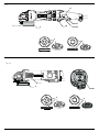
Fig. A-1
6
7
8
10
2
5
4
Fig. A-2
10
5
4
7
6
11

2
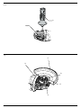
Fig. B
Fig. C
3
1
6
13
9
12
6
14

3
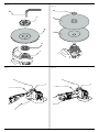
Fig. D-2
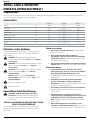
Fig. G-1
Fig. D-1
20
5
16
4
2
19
18
17
3
Fig. G-2
3

4
ENGLISH
Work area safety
a ) Keep work area clean and well lit. Cluttered or dark
areas inviteaccidents.
b ) Do not operate power tools in explosive
atmospheres, such as in the presence of flammable
liquids, gases or dust. Power tools create sparks which
may ignite the dust orfumes.
c ) Keep children and bystanders away while operating
a power tool. Distractions can cause you to losecontrol.
Electrical safety
d ) Power tool plugs must match the outlet. Never
modify the plug in any way. Do not use any adapter
plugs with earthed (grounded) power tools.
Unmodified plugs and matching outlets will reduce risk of
electricshock.
e ) Avoid body contact with earthed or grounded
surfaces such as pipes, radiators, ranges and
refrigerators. There is an increased risk of electric shock if
your body is earthed orgrounded.
f ) Do not expose power tools to rain or wet conditions.
Water entering a power tool will increase the risk of
electricshock.
g ) Do not abuse the cord. Never use the cord for
carrying, pulling or unplugging the power tool. Keep
cord away from heat, oil, sharp edges or moving
parts. Damaged or entangled cords increase the risk of
electricshock.
h ) When operating a power tool outdoors, use an
extension cord suitable for outdoor use. Use of a cord
suitable for outdoor use reduces the risk of electricshock.
Definitions: Safety Guidelines
The definitions below describe the level of severity for each
signal word. Please read the manual and pay attention to
thesesymbols.
DANGER: Indicates an imminently hazardous
situation which, if not avoided, will result in death or
seriousinjury.
WARNING: Indicates a potentially hazardous situation
which, if not avoided, could result in death or
seriousinjury.
CAUTION: Indicates a potentially hazardous situation
which, if not avoided, may result in minor or
moderateinjury.
NOTICE: Indicates a practice not related to
personal injury which, if not avoided, may result in
propertydamage.
Denotes risk of electricshock.
Denotes risk offire.
General Power Tool Safety Warnings
WARNING: Read all safety warnings and all
instructions. Failure to follow the warnings and
instructions may result in electric shock, fire and/or
seriousinjury.
SAVE ALL WARNINGS AND INSTRUCTIONS
FOR FUTURE REFERENCE
The term “power tool” in the warnings refers to your mains-
operated (corded) power tool or battery-operated (cordless)
powertool.
English (original instructions)
SMALL ANGLE GRINDERS
DWE8410,DWE8420,DWE8411
Congratulations!
You have chosen a DeWALT tool. Years of experience, thorough product development and innovation make DeWALT one of the
most reliable partners for professional power toolusers.
Technical Data
DWE8410 DWE8420 DWE8411
Voltage V
AC
220-240 220-240 220-240
Power input W 1400
1400
1400
rated speed r/min 10500 9500 10500
Wheel diameter mm 125 150 125
Wheel thickness (max) mm 6.0
6.0
6.0
Spindle diameter M14
M14
M14
Spindle length mm 18.5 18.5 18.5
Weight kg 2.5* 2.5* 2.5*
* weight includes side handle and guard

5
ENGLISH
i ) If operating a power tool in a damp location is
unavoidable, use a residual current device (RCD)
protected supply. Use of an RCD reduces the risk of
electricshock.
Personal safety
j ) Stay alert, watch what you are doing and use
common sense when operating a power tool. Do not
use a power tool while you are tired or under the
influence of drugs, alcohol or medication. A moment
of inattention while operating power tools may result in
serious personalinjury.
k ) Use personal protective equipment. Always wear
eye protection. Protective equipment such as dust mask,
non-skid safety shoes, hard hat, or hearing protection used
for appropriate conditions will reduce personalinjuries.
l ) Prevent unintentional starting. Ensure the switch
is in the off position before connecting to power
source and/or battery pack, picking up or carrying
the tool. Carrying power tools with your finger on the
switch or energising power tools that have the switch on
invitesaccidents.
m ) Remove any adjusting key or wrench before turning
the power tool on. A wrench or a key left attached
to a rotating part of the power tool may result in
personalinjury.
n ) Do not overreach. Keep proper footing and balance
at all times. This enables better control of the power tool
in unexpectedsituations.
o ) Dress properly. Do not wear loose clothing or
jewellery. Keep your hair, clothing and gloves away
from moving parts. Loose clothes, jewellery or long hair
can be caught in movingparts.
p ) If devices are provided for the connection of dust
extraction and collection facilities, ensure these are
connected and properly used. Use of dust collection
can reduce dust-relatedhazards.
Power tool use and care
q ) Do not force the power tool. Use the correct power
tool for your application. The correct power tool
will do the job better and safer at the rate for which it
wasdesigned.
r ) Do not use the power tool if the switch does not turn
it on and off. Any power tool that cannot be controlled
with the switch is dangerous and must berepaired.
s ) Disconnect the plug from the power source and/or
the battery pack from the power tool before making
any adjustments, changing accessories, or storing
power tools. Such preventive safety measures reduce the
risk of starting the power toolaccidentally.
t ) Store idle power tools out of the reach of children
and do not allow persons unfamiliar with the power
tool or these instructions to operate the power tool.
Power tools are dangerous in the hands of untrainedusers.
u ) Maintain power tools. Check for misalignment or
binding of moving parts, breakage of parts and any
other condition that may affect the power tool’s
operation. If damaged, have the power tool repaired
before use. Many accidents are caused by poorly
maintained powertools.
v ) Keep cutting tools sharp and clean. Properly
maintained cutting tools with sharp cutting edges are less
likely to bind and are easier tocontrol.
w ) Use the power tool, accessories and tool bits etc.,
in accordance with these instructions taking into
account the working conditions and the work to be
performed. Use of the power tool for operations different
from those intended could result in a hazardoussituation.
Service
x ) Have your power tool serviced by a qualified repair
person using only identical replacement parts. This
will ensure that the safety of the power tool ismaintained.
ADDITIONAL SPECIFIC SAFETY RULES
Safety Instructions for All Operations
a ) This power tool is intended to function as a
grinder, sander, wire brush or cut-off tool. Read
all safety warnings, instructions, illustrations and
specifications provided with this power tool. Failure
to follow all instructions listed below may result in electric
shock, fire and/or seriousinjury.
b ) Operations such as polishing are not recommended
to be performed with this power tool. Operations for
which the power tool was not designed may create a
hazard and cause personalinjury.
c ) Do not use accessories which are not specifically
designed and recommended by the tool
manufacturer. Just because the accessory can
be attached to your power tool, it does not assure
safeoperation.
d ) The rated speed of the accessory must be at least
equal to the maximum speed marked on the power
tool. Accessories running faster than their rated speed can
break and flyapart.
e ) The outside diameter and the thickness of your
accessory must be within the capacity rating of
your power tool. Incorrectly sized accessories can not be
adequately guarded orcontrolled.
f ) Threaded mounting of accessories must match the
grinder spindle thread. For accessories mounted by
flanges, the arbour hole of the accessory must fit the
locating diameter of the flange. Accessories that do
not match the mounting hardware of the power tool will
run out of balance, vibrate excessively and may cause loss
ofcontrol.
g ) Do not use a damaged accessory. Before each use
inspect the accessory such as abrasive wheel for
chips and cracks, backing pad for cracks, tear or
excess wear, wire brush for loose or cracked wires.

6
ENGLISH
If power tool or accessory is dropped, inspect for
damage or install an undamaged accessory. After
inspecting and installing an accessory, position
yourself and bystanders away from the plane of
the rotating accessory and run the power tool at
maximum no-load speed for one minute. Damaged
accessories will normally break apart during this testtime.
h ) Wear personal protective equipment. Depending on
application, use face shield, safety goggles or safety
glasses. As appropriate, wear dust mask, hearing
protectors, gloves and workshop apron capable of
stopping small abrasive or workpiece fragments.
The eye protection must be capable of stopping flying
debris generated by various operations. The dust mask or
respirator must be capable of filtrating particles generated
by your operation. Prolonged exposure to high intensity
noise may cause hearingloss.
i ) Keep bystanders a safe distance away from work
area. Anyone entering the work area must wear
personal protective equipment. Fragments of
workpiece or of a broken accessory may fly away and
cause injury beyond immediate area ofoperation.
j ) Hold the power tool by insulated gripping surfaces
only, when performing an operation where the
cutting accessory may contact hidden wiring or its
own cord. Cutting accessory contacting a "live" wire may
make exposed metal parts of the power tool "live" and
could give the operator an electricalshock.
k ) Position the cord clear of the spinning accessory. If
you lose control, the cord may be cut or snagged and your
hand or arm may be pulled into the spinningaccessory.
l ) Never lay the power tool down until the accessory
has come to a complete stop. The spinning accessory
may grab the surface and pull the power tool out of
yourcontrol.
m ) Do not run the power tool while carrying it at your
side. Accidental contact with the spinning accessory
could snag your clothing, pulling the accessory into
yourbody.
n ) Regularly clean the power tool’s air vents. The
motor’s fan will draw the dust inside the housing and
excessive accumulation of powdered metal may cause
electricalhazards.
o ) Do not operate the power tool near flammable
materials. Sparks could ignite thesematerials.
p ) Do not use accessories that require liquid coolants.
Using water or other liquid coolants may result in
electrocution orshock.
q ) Do not use Type 11 (flaring cup) wheels on this tool.
Using inappropriate accessories can result ininjury.
r ) Always use side handle. Tighten the handle securely.
The side handle should always be used to maintain control
of the tool at alltimes.
FURTHER SAFETY INSTRUCTIONS FOR ALL
OPERATIONS
Causes and Operator Prevention
of Kickback
Kickback is a sudden reaction to a pinched or snagged rotating
wheel, backing pad, brush or any other accessory. Pinching or
snagging causes rapid stalling of the rotating accessory which
in turn causes the uncontrolled power tool to be forced in the
direction opposite of the accessory’s rotation at the point of
thebinding.
For example, if an abrasive wheel is snagged or pinched by the
workpiece, the edge of the wheel that is entering into the pinch
point can dig into the surface of the material causing the wheel
to climb out or kick out. The wheel may either jump toward or
away from the operator, depending on direction of the wheel’s
movement at the point of pinching. Abrasive wheels may also
break under theseconditions.
Kickback is the result of tool misuse and/or incorrect operating
procedures or conditions and can be avoided by taking proper
precautions as given below:
a ) Maintain a firm grip on the power tool and position
your body and arm to allow you to resist kickback
forces. Always use auxiliary handle, if provided, for
maximum control over kickback or torque reaction
during start up. The operator can control torque reaction
or kickback forces, if proper precautions aretaken.
b ) Never place your hand near the rotating accessory.
Accessory may kickback over yourhand.
c ) Do not position your body in the area where power
tool will move if kickback occurs. Kickback will propel
the tool in direction opposite to the wheel’s movement at
the point ofsnagging.
d ) Use special care when working corners, sharp edges
etc. Avoid bouncing and snagging the accessory.
Corners, sharp edges or bouncing have a tendency to
snag the rotating accessory and cause loss of control
orkickback.
e ) Do not attach a saw chain woodcarving blade or
toothed saw blade. Such blades create frequent kickback
and loss ofcontrol.
Safety Warnings Specific for Grinding and
Abrasive Cutting-Off Operations
a ) Use only wheel types that are recommended for your
power tool and the specific guard designed for the
selected wheel. Wheels for which the power tool was not
designed cannot be adequately guarded and areunsafe.
b ) The grinding surface of centre depressed wheels
must be mounted below the plane of the guard lip.
An improperly mounted wheel that projects through the
plane of the guard lip cannot be adequatelyprotected.

7
ENGLISH
c ) The guard must be securely attached to the power
tool and positioned for maximum safety, so the least
amount of wheel is exposed towards the operator.
The guard helps to protect the operator from broken wheel
fragments, accidental contact with wheel and sparks that
could igniteclothing.
d ) Wheels must be used only for recommended
applications. For example: do not grind with the side
of cut-off wheel. Abrasive cut-off wheels are intended
for peripheral grinding, side forces applied to these wheels
may cause them toshatter.
e ) Always use undamaged wheel flanges that are
of correct size and shape for your selected wheel.
Proper wheel flanges support the wheel thus reducing the
possibility of wheel breakage. Flanges for cut-off wheels
may be different from grinding wheelflanges.
f ) Do not use worn down wheels from larger power
tools. Wheel intended for larger power tool is not suitable
for the higher speed of a smaller tool and mayburst.
Additional Safety Warnings Specific for
Abrasive Cutting-Off Operations
a ) Do not "jam" the cut-off wheel or apply excessive
pressure. Do not attempt to make an excessive depth
of cut. Overstressing the wheel increases the loading and
susceptibility to twisting or binding of the wheel in the cut
and the possibility of kickback or wheelbreakage.
b ) Do not position your body in line with and behind
the rotating wheel. When the wheel, at the point of
operations, is moving away from your body, the possible
kickback may propel the spinning wheel and the power
tool directly atyou.
c ) When wheel is binding or when interrupting a cut
for any reason, switch off the power tool and hold
the power tool motionless until the wheel comes to
a complete stop. Never attempt to remove the cut-
off wheel from the cut while the wheel is in motion
otherwise kickback may occur. Investigate and take
corrective action to eliminate the cause of wheelbinding.
d ) Do not restart the cutting operation in the
workpiece. Let the wheel reach full speed and
carefully re-enter the cut. The wheel may bind, walk up
or kickback if the power tool is restarted in theworkpiece.
e ) Support panels or any oversized workpiece to
minimize the risk of wheel pinching and kickback.
Large workpieces tend to sag under their own weight.
Supports must be placed under the workpiece near the line
of cut and near the edge of the workpiece on both sides
of thewheel.
f ) Use extra caution when making a “pocket cut” into
existing walls or other blind areas. The protruding
wheel may cut gas or water pipes, electrical wiring or
objects that can causekickback.
Safety Warnings Specific for Sanding
Operations
a ) Do not use excessively oversized sanding disc
paper. Follow manufacturer’s recommendations,
when selecting sanding paper. Larger sanding paper
extending beyond the sanding pad presents a laceration
hazard and may cause snagging, tearing of the disc
orkickback.
Safety Warnings Specific for Wire Brushing
Operations
a ) Be aware that wire bristles are thrown by the brush
even during ordinary operation. Do not overstress
the wires by applying excessive load to the brush.
The wire bristles can easily penetrate llight clothing and/
orskin.
b ) If the use of a guard is recommended for wire
brushing, do not allow any interference of the
wire wheel or brush with the guard. Wire wheel
or brush may expand in diameter due to work and
centrifugalforces.
Additional Safety Rules for Grinders
• Threaded mounting of accessories must match the grinder
spindle thread. For accessories mounted by flanges, the arbor
hole of the accessory must fit the locating diameter of the
flange. Accessories that do not match the mounting hardware
of the power tool will run out of balance, vibrate excessively
and may cause loss ofcontrol.
• The grinding surface of the centre depressed wheels must
be mounted below the plane of the guard lip. An improperly
mounted wheel that projects through the plane of the guard
lip cannot be adequatelyprotected.
WARNING: We recommend the use of a residual current
device with a residual current rating of 30mA or less.
Residual Risks
In spite of the application of the relevant safety regulations
and the implementation of safety devices, certain residual risks
cannot be avoided. These are:
• Impairment ofhearing.
• Risk of personal injury due to flyingparticles.
• Risk of burns due to accessories becoming hot
duringoperation.
• Risk of personal injury due to prolongeduse.
• Risk of dust from hazardoussubstances.
Electrical Safety
The electric motor has been designed for one voltage only.
Always check that the power supply corresponds to the voltage
on the rating plate.
Your DeWALT tool is double insulated in accordance
with IEC60745; therefore no earth wire is required.

8
ENGLISH
If the supply cord is damaged, it must be replaced by a
specially prepared cord available through the DeWALT
serviceorganisation.
Using an Extension Cable
An extension cord should not be used unless absolutely
necessary. Use an approved extension cable suitable for
the power input of your charger (see Technical Data). The
minimum conductor size is 1.5 mm
2
; the maximum length
is30m.
When using a cable reel, always unwind the cablecompletely.
Package Contents
The package contains:
1 Angle grinder
1 Guard
1 Side handle
1 Flange set
1 Hex key
1 Instruction manual
• Check for damage to the tool, parts or accessories which may
have occurred duringtransport.
• Take the time to thoroughly read and understand this manual
prior tooperation.
Markings on Tool
The following pictograms are shown on the tool:
Read instruction manual before use.
Wear ear protection.
Wear eye protection.
Date Code Position (Fig. C)
The date code
14
, which also includes the year of manufacture,
is printed into thehousing.
Example:
2016 XX XX
Year of Manufacture
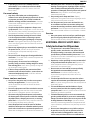
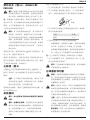
Description (Fig.A,B)
WARNING: Never modify the power tool or any part of it.
Damage or personal injury couldresult.
1
Spindle lock button
2
Spindle
3
Side handle
4
Backing flange
5
Clamp nut
6
Guard
7
Trigger switch(Fig.A-1)(DWE8411)
Slide switch(Fig.A-2)(DWE8410 and DWE8420)
8
Lock-off lever
10
Dust ejection system
11
Lock on buton
Intended Use
Your heavy-duty small angle grinder has been designed
for professional grinding, sanding, wire brushing and
cuttingapplications.
DO NOT use grinding wheels other than centre depressed
wheels and flapdiscs.
DO NOT use under wet conditions or in the presence of
flammable liquids orgases.
Your heavy-duty angle grinders is a professional power tool.
DO NOT let children come into contact with the tool.
Supervision is required when inexperienced operators use
thistool.
• Young children and the infirm. This appliance is not
intended for use by young children or infirm persons
without supervision.
• This product is not intended for use by persons (including
children) suffering from diminished physical, sensory or
mental abilities; lack of experience, knowledge or skills
unless they are supervised by a person responsible for their
safety. Children should never be left alone with thisproduct.
Dust Ejection System (Fig.A)
The dust ejection system
10
prevents dust pile-up around
the guard and motor inlet, and minimises the amount of dust
entering the motorhousing.
ASSEMBLY AND ADJUSTMENTS
WARNING: To reduce the risk of serious personal
injury, turn tool off and disconnect tool from power
source before making any adjustments or removing/
installing attachments or accessories. Be sure the
trigger switch is in the OFF position. An accidental start-up
can cause injury.
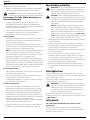
Attaching Side Handle (Fig.B)
WARNING: Before using the tool, check that the handle is
tightenedsecurely.
Screw the side handle
3
tightly into one of the holes on either
side of the gear case. The side handle should always be used to
maintain control of the tool at alltimes.
Mounting Guards
WARNING: To reduce the risk of
serious personal injury, turn tool
off and disconnect tool from power
source before making any adjustments
or removing/installing attachments or
accessories. Before reconnecting the tool,
depress and release the trigger switch to
ensure that the tool is off.
CAUTION: Guards must be used with all
grinding wheels, cutting wheels, sanding flap
discs, wire brushes, and wire wheels. The tool
may be used without a guard only when sanding

9
ENGLISH
with conventional sanding discs. Refer to Figure
A to see guards provided with the unit. Some
applications may require purchasing the correct
guard from your local dealer or authorized service
centre.
Mounting and Removing the Guard (fig.
C)
WARNING: To reduce the risk of
serious personal injury, turn tool
off and disconnect tool from power
source before making any adjustments
or removing/installing attachments or
accessories. Before reconnecting the tool,
depress and release the trigger switch to
ensure that the tool is off.
MOUNTING CLOSED (TYPE 1) OR STANDARD (TYPE 27)
GUARD
CAUTION: Turn off and unplug the tool
before making anyadjustments or removing
or installing attachments or acces-sories.
Before reconnecting the tool, turn the
switch on and off to ensure that the tool is
off.
Hubbed wheels install directly on the M14 spindle.
Thread of accessory must match thread of spindle.
1. Loosen screw, until the guard lug (13) can rotate
freely in the groove (12) on the gear case hub.
2. Rotate guard (6) into desired working position.
The guard body should be positioned between
the spindle and the operator toprovide maximum
operator protection.
3. Tighten the screw(9) to secure the guard on the
gear case cover. (Fasten torque no less than 2.5
N-M). You should be unable to rotate the guard
by hand. Do not operate grinder with a loose
guard.
4. To remove the guard, loosen screw and pull up on
the guard.
TO REMOVE THE GUARD
1. Loosen the screw holding the cinch collar around
the neck of the spindle.
2. Lift up on the guard.
1.
WARNING: Never use the tool without the
guard in place.
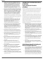
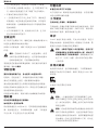
Flanges and Wheels
Mounting Non-Hubbed Wheels (Fig. D-1)
WARNING: Failure to properly seat the flange/ clamp nut/
wheel could result in serious injury (or damage to the tool
or wheel).
CAUTION: Included flanges must be used with depressed
centre Type 27 and Type 42 grinding wheels and Type41
cutting wheels. See the Accessories Chart for more
information.
WARNING: A closed, two-sided cutting wheel guard is
re quired when using cutting wheels.
WARNING: Use of a damaged flange or guard or fail ure
to use proper flange and guard can re sult in injury due to
wheel breakage and wheel contact. See the Accessories
Chart for more information.
1. Place the tool on a table, guard up.
2. Install the unthreaded backing flange
4
on spindle
2
with
the raised centre (pilot) facing the wheel.
3. Place wheel
16
against the backing flange, centreing the
wheel on the raised centre (pilot) of the backing flange.
4. While depressing the spindle lock button and with the
hex depressions facing away from the wheel, thread the
clampnut
5
on spindle so that the lugs engage the two
slots in the spindle.
5. While depressing the spindle lock button, tighten the
locking flange with a wrench
20
.
6. To remove the wheel, depress the spindle lock button and
loosen the threaded locking flange with a wrench.
Mounting Sanding Backing Pads (Fig.D-2)
NOTE: Use of a guard with sanding discs that use backing pads,
often called fiber resin discs, is not required. Since a guard is
not required for these accessories, the guard may or may not fit
correctly if used.
WARNING: Failure to properly seat the flange/ clamp nut/
wheel could result in serious injury (or damage to the tool
or wheel).
WARNING: Proper guard must be reinstalled for grinding
wheel, cutting wheel, sanding flap disc, wire brush or
wire wheel applications after sanding applications are
complete.
1. Place or appropriately thread backing pad
17
on
thespindle.
2. Place the sanding disc
18
on the backing pad
17
.
3. While depressing spindle lock
1
, thread clamp nut
19
on
spindle, piloting the raised hub on the clamp nut into the
centre of san ding disc and backingpad.
4. Tighten the clamp nut by hand. Then depress the spindle
lock button while turning the sanding disc until the sanding
disc and clamp nut are snug.
5. To remove the wheel, grasp and turn the backing pad and
sanding pad while depressing the spindle lock button.

10
ENGLISH
Mounting and Removing Hubbed Wheels
Hubbed wheels install directly on the M14 threaded spindle.
Thread of accessory must match thread of spindle.
1. Remove backing flange by pulling away from tool.
2. Thread the wheel on the spindle
2
by hand.
3. Depress the spindle lock button
1
and use a wrench to
tighten the hub of the wheel.
4. Reverse the above procedure to remove the wheel.
NOTICE: Failure to properly seat the wheel before turning
the tool on may result in damage to the tool or the wheel.
Mounting Wire Cup Brushes and
Wire Wheels
WARNING: Failure to properly seat the flange/ clamp nut/
wheel could result in serious injury (or damage to the tool
or wheel).
CAUTION: To reduce the risk of personal injury,
wear work gloves when handling wire brushes and
wheels. They can become sharp.
CAUTION: To reduce the risk of damage to the tool,
wheel or brush must not touch guard when mounted
or while in use. Undetectable damage could occur to
the accessory, causing wires to fragment from accessory
wheel or cup.
Wire cup brushes or wire wheels install directly on the threaded
spindle without the use of flanges. Use only wire brushes or
wheels provided with a M14 threaded hub. These accessories
are available at extra cost from your local dealer or authorised
service centre.
1. Place the tool on a table, guard up.
2. Thread the wheel on the spindle by hand.
3. Depress spindle lock button
1
and use a wrench on the
hub of the wire wheel or brush to tighten the wheel.
4. To remove the wheel, reverse the above procedure.
NOTICE: To reduce the risk of damage to the tool, properly
seat the wheel hub before turning the tool on.
Prior to Operation
• Install the guard and appropriate disc or wheel. Do not use
excessively worn discs orwheels.
• Be sure the inner and outer flange are mounted correctly.
Follow the instructions given in the Grinding and Cutting
AccessoryChart.
• Make sure the disc or wheel rotates in the direction of the
arrows on the accessory and thetool.
• Do not use a damaged accessory. Before each use inspect
the accessory such as abrasive wheels for chips and cracks,
backing pad for cracks, tear or excess wear, wire brush for
loose or cracked wires. If power tool or accessory is dropped,
inspect for damage or install an undamaged accessory. After
inspecting and installing an accessory, position yourself and
bystanders away from the plane of the rotating accessory
and run the power tool at maximum no-load speed for one
minute. Damaged accessories will normally break apart
during this testtime.
OPERATION
Instructions for Use
WARNING: Always observe the safety instructions and
applicableregulations.
WARNING: To reduce the risk of serious personal
injury, turn tool off and disconnect tool from power
source before making any adjustments or removing/
installing attachments or accessories. Be sure the
trigger switch is in the OFF position. An accidental start-up
can cause injury.
WARNING:
• Ensure all materials to be ground or cut are secured
inplace.
• Secure and support the workpiece. Use clamps or a
vice to hold and support the workpiece to a stable
platform. It is important to clamp and support the
workpiece securely to prevent movement of the
workpiece and loss of control. Movement of the
workpiece or loss of control may create a hazard and
cause personalinjury.
• Support panels or any oversized workpiece
to minimize the risk of wheel pinching and
kickback. Large workpieces tend to sag under their
own weight. Supports must be placed under the
workpiece near the line of cut and near the edge of the
workpiece on both sides of thewheel.
• Always wear regular working gloves while operating
thistool.
• The gear becomes very hot duringuse.
• Apply only a gentle pressure to the tool. Do not exert
side pressure on thedisc.
• Always install the guard and appropriate disc or
wheel. Do not use excessively worn disc or wheel.
• Be sure the inner and outer flange are
mountedcorrectly.
• Make sure the disc or wheel rotates in the direction of
the arrows on the accessory and thetool.
• Avoid overloading. Should the tool become hot, let it
run a few minutes under no load condition to cool the
accessory. Do not touch accessories before they have
cooled. The discs become very hot duringuse.
• Never work with the grinding cup without a suitable
protection guard inplace.
• Do not use the power tool with a cut-offstand.
• Never use blotters together with bonded
abrasiveproducts.
• Be aware, the wheel continues to rotate after the tools
is switchedoff.
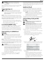
Proper Hand Position (Fig.G)
WARNING: To reduce the risk of serious personal injury,
ALWAYS use proper hand position asshown.

11
ENGLISH
WARNING: To reduce the risk of serious personal
injury, ALWAYS hold securely in anticipation of a
suddenreaction.
Proper hand position requires one hand on the side handle
3
,
with the other hand on the body of the tool, as shown in
FigureG.
Trigger Switch (Fig.A-1)
CAUTION: Hold the side handle and body of the tool
firmly to maintain control of the tool at start up and
during use and until the wheel or accessory stops rotating.
Make sure the wheel has come to a complete stop be fore
laying the tooldown.
NOTE: To reduce unexpected tool movement, do not switch
the tool on or off while under load conditions. Allow the grinder
to run up to full speed before touching the work surface. Lift the
tool from the surface before turning the tool off. Allow the tool
to stop rotating before putting itdown.
1. To turn the tool on, push the lock-off lever
(
8
)
toward the
back of the tool, then depress the trigger switch
(
7
)
. The tool
will run while the switch isdepressed.
2. Turn the tool off by releasing the triggerswitch.
Lock-On Button(DWE8411 Only)
The lock-on button
11
offers increased comfort in extended
use applications. To lock the tool on, depress the lock-on
button when the tool is running. The tool will continue to run
after the paddle switch is released. To unlock the tool, depress
and release the paddle switch. This will cause the tool to stop.
Slider Switch (Fig.A-2) (DWE8410 and
DWE8420)
CAUTION: Hold the side handle and body of the tool
firmly to maintain control of the tool at start up and
during use and until the wheel or accessory stops rotating.
Make sure the wheel has come to a complete stop be fore
laying the tooldown.
NOTE: To reduce unexpected tool movement, do not switch
the tool on or off while under load conditions. Allow the grinder
to run up to full speed before touching the work surface. Lift the
tool from the surface before turning the tool off. Allow the tool
to stop rotating before putting itdown.
WARNING: Before connecting the tool to a power supply,
be sure the slider switch is in the off position by pressing
the rear part of the switch and releasing. Ensure the slider
switch is in the off position as described above after any
interruption in power supply to the tool, such as the
activation of a ground fault interrupter, throwing of a
circuit breaker, accidental unplugging, or power failure. If
the slider switch is locked on when the power is connected,
the tool will startunexpectedly.
To start the tool, slide the ON/OFF slider switch
(
7
)
toward
the front of the tool. To stop the tool, release the ON/OFF
sliderswitch.
For continuous operation, slide the switch toward the front of
the tool and press the forward part of the switch inward. To stop
the tool while operating in continuous mode, press the rear part
of the slider switch andrelease.
Spindle Lock (Fig.B)
The spindle lock
1
is provided to prevent the spindle from
rotating when installing or removing wheels. Operate the
spindle lock only when the tool is turned off, unplugged from
the power supply, and has come to a completestop.
NOTICE: To reduce the risk of damage to the tool, do
not engage the spindle lock while the tool is operating.
Damage to the tool will result and attached accessory
may spin off possibly resulting ininjury.
To engage the lock, depress the spindle lock button and rotate
the spindle until you are unable to rotate the spindlefurther.
Surface Grinding, Sanding and Wire
Brushing
CAUTION: Always use the correct guard per the
instructions in this manual.
WARNING: Metal dust build-up. Extensive use of flap
discs in metal applications can result in the increased
potential for electric shock. To reduce this risk, insert an
RCD before use and clean the ventilation slots daily by
blowing dry compressed air into the ventilation slots
inaccordance with the below maintenanceinstructions.
To perform work on a the surface of a workpiece:
1. Allow the tool to reach full speed before touching the tool
to the work surface.
2. Apply minimum pressure to the work surface, allowing
the tool to operate at high speed. Material removal rate is
greatest when the tool operates at high speed.
Angle
3. Maintain an appropriate angle between the tool and work
surface. Refer to the chart according to particularfunction.
Function Angle
Grinding 20˚-30˚
Sanding with Flap Disc 5˚-10˚
Sanding with Backing Pad 5˚-15˚
Wire Brushing 5˚-10˚
4. Maintain contact between the edge of the wheel and the
work surface.
- If grinding, sanding with flap discs or wire brushing
move the tool continuously in a forward and back
motion to avoid creating gouges in the worksurface.
- If sanding with a backing pad, move the tool constantly
in a straight line to prevent burning and swirling of
worksurface.

12
ENGLISH
NOTE: Allowing the tool to rest on the work surface without
moving will damage the work piece.
5. Remove the tool from work surface before turning tool off.
Allow the tool to stop rotating before laying it down.
CAUTION: Use extra care when working over an edge, as
a sudden sharp movement of grinder may be experienced.
Precautions To Take When Working on a
Painted Workpiece
1. Sanding or wire brushing of lead based paint is NOT
RECOMMENDED due to the difficulty of controlling the
contaminated dust. The greatest danger of lead poisoning is
to children and pregnant women.
2. Since it is difficult to identify whether or not a paint contains
lead without a chemical analysis, we recommend the
following precautions when sanding any paint:
Personal Safety
1. No children or pregnant women should enter the work area
where the paint sanding or wire brushing is being done
until all clean up is completed.
2. A dust mask or respirator should be worn by all persons
entering the work area. The filter should be replaced daily or
whenever the wearer has difficulty breathing.
NOTE: Only those dust masks suitable for working with lead
paint dust and fumes should be used. Ordinary painting
masks do not offer this protection. See your local hardware
dealer for the proper N.I.O.S.H. approved mask.
3. NO EATING, DRINKING or SMOKING should be done in the
work area to prevent ingesting contaminated paint particles.
Workers should wash and clean up BEFORE eating, drinking
or smoking. Articles of food, drink, or smoking should not be
left in the work area where dust would settle on them.
Environmental Safety
1. Paint should be removed in such a manner as to minimize
the amount of dust generated.
2. Areas where paint removal is occurring should be sealed
with plastic sheeting of 4 mils thickness.
3. Sanding should be done in a manner to reduce tracking of
paint dust outside the work area.
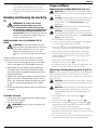
Cleaning and Disposal
1. All surfaces in the work area should be vacuumed and
thoroughly cleaned daily for the duration of the sanding
project. Vacuum filter bags should be changedfrequently.
2. Plastic drop cloths should be gathered up and disposed
of along with any dust chips or other removal debris. They
should be placed in sealed refuse receptacles and disposed
of through regular trash pick-up procedures.
During clean up, children and pregnant women should be
kept away from the immediate work area.
3. All toys, washable furniture and utensils used by children
should be washed thoroughly before being used again.
Edge Grinding and Cutting
WARNING: Do not use edge grinding/cutting wheels for
surface grinding applications because these wheels are
not designed for side pressures encountered with surface
grinding. Wheel breakage and injury may result.
CAUTION: Wheels used for edge grinding and cutting
may break or kick back if they bend or twist while the tool
is being used. In all edge grinding/cutting operations, the
open side of the guard must be positioned away from
theoperator.
NOTICE: Edge grinding/cutting with a Type27 wheel
must be limited to shallow cutting and notching—less
than 13mm in depth when the wheel is new. Reduce the
depth of cutting/notching equal to the reduction of the
wheel radius as it wears down. Refer to the Accessories
Chart for more information. Edge grinding/cutting with a
Type 41 wheel requires usage of a Type 1 guard.
1. Allow the tool to reach full speed before touching the tool
to the work surface.
2. Apply minimum pressure to the work surface, allowing
the tool to operate at high speed. Grinding/cutting rate is
greatest when the tool operates at high speed.
3. Position yourself so that the open-underside of the wheel is
facing away from you.
4. Once a cut is begun and a notch is established in the
workpiece, do not change the angle of the cut. Changing
the angle will cause the wheel to bend and may cause
wheel breakage. Edge grinding wheels are not designed to
withstand side pressures caused bybending.
5. Remove the tool from the work surface before turning
the tool off. Allow the tool to stop rotating before laying
itdown.
Metal Applications
When using the tool in metal applications, make sure that a
residual current device (RCD) has been inserted to avoid residual
risks caused by metal swarf.
If the power supply is shut off by the RCD, take the tool to an
authorised D
eWALT repair agent.
WARNING: In extreme working conditions, conductive
dust can accumulate inside the machine housing when
working with metal. This can result in the protective
insulation in the machine becoming degraded with a
potential risk of an electrical shock.
To avoid build-up of metal swarf inside the machine, we
recommend to clear the ventilation slots on a daily basis. Refer
to Maintenance.
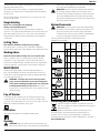
Cutting Metal
For cutting with bonded abrasives, always use the
guardtype 1.
When cutting, work with moderate feed, adapted to the
material being cut. Do not exert pressure onto the cutting disc,
tilt or oscillate the machine.

13
ENGLISH
Do not reduce the speed of running down cutting discs by
applying sideward pressure.
The machine must always work in an upgrinding motion.
Otherwise, the danger exists of it being pushed uncontrolled
out of the cut.
When cutting profiles and square bar, it is best to start at the
smallest cross section.
Rough Grinding
Never use a cutting disc for roughing.
Always use the guard type 27.
The best roughing results are achieved when setting the
machine at an angle of 30° to 40°. Move the machine back and
forth with moderate pressure. In this manner, the workpiece
will not become too hot, does not discolour and no grooves
areformed.
Cutting Stone
The machine shall be used only for dry cutting.
For cutting stone, it is best to use a diamond cutting disc.
Operate the machine only with additional dust protection mask.
Working Advice
Exercise caution when cutting slots in structural walls.
Slots in structural walls are subject to the country-specific
regulations. These regulations are to be observed under all
circumstances.Before beginning work, consult the responsible
structural engineer, architect or the construction supervisor.
MAINTENANCE
Your DeWALT power tool has been designed to operate
over a long period of time with a minimum of maintenance.
Continuous satisfactory operation depends upon proper tool
care and regularcleaning.
WARNING: To reduce the risk of serious personal
injury, turn tool off and disconnect tool from power
source before making any adjustments or removing/
installing attachments or accessories. Be sure the
trigger switch is in the OFF position. An accidental start-up
can cause injury.
Pop-off Brushes
The motor will be automatically shut off indicating that the
carbon brushes are nearly worn out and that the tool needs
servicing. The carbon brushes are not user-serviceable. Take the
tool to an authorised DeWALT repairagent.
Lubrication
Your power tool requires no additionallubrication.
Cleaning
WARNING: Blow dirt and dust out of the main housing
with dry air as often as dirt is seen collecting in and around
the air vents. Wear approved eye protection and approved
dust mask when performing thisprocedure.
WARNING: Never use solvents or other harsh chemicals
for cleaning the non-metallic parts of the tool. These
chemicals may weaken the materials used in these parts.
Use a cloth dampened only with water and mild soap.
Never let any liquid get inside the tool; never immerse any
part of the tool into aliquid.
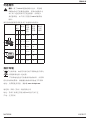
Optional Accessories
WARNING: Since accessories, other than those offered
by
DeWALT, have not been tested with this product, use
of such accessories with this tool could be hazardous.
To reduce the risk of injury, only DeWALT recommended
accessories should be used with thisproduct.
Consult your dealer for further information on the
appropriateaccessories.
Max.
[mm]
[mm]
Min.
Rotation
[min.
–1
]
Periphical
speed
[m/s]
Threaded
hole length
[mm]
D b d
d
D
b
115 6 22,23 11,500 80 –
125 6 22,23 11,500 80 –
150 6 22,23 9,500 80
D
115 – – 11,500 80 –
125 – – 11,500 80 –
D
d
b
75 30 M14 11,500 45 20.0
D
115 12 M14 11,500 80 20.0
125 12 M14 11,500 80 20.0
Protecting the Environment
Separate collection. Products and batteries marked
with this symbol must not be disposed of with normal
household waste.
Products and batteries contain materials that can
be recovered or recycled reducing the demand for raw
materials. Please recycle electrical products and batteries
according to local provisions. Further information is available at
www.2helpU.com.

14
简体中文
下列所有警告中的“电动工具”一词是指电源驱动
(有线)电动工具,或者电池驱动(无线)电动工
具。
a) 工作场地的安全
1) 保持工作场地清洁和明亮。混乱和黑暗的场地会
引发事故。
2) 不要在易爆环境,如有易燃液体、气体或粉尘的
环境下操作电动工具。电动工具产生的火花会点
燃粉尘或气体。
3) 让儿童和旁观者离开后操作电动工具。注意力不
集中会使你失去对工具的控制。
)b 电气安全
1) 电动工具插头必须与插座相配。绝不能以任何方
式改装插头。需接地的电动工具不能使用任何转
换插头。未经改装的插头和相配的插座将减少电
击危险。
2) 避免人体接触接地表面,如管道、散热片和冰
箱。如果你身体接地会增加电击危险。
定义:安全指南
下列定义描述了各标志术语的严重程度。请仔细阅读
本手册,并注意这些标志。
危险:表示存在紧急危险情况,如果不加以避
免,将导致死亡或严重伤害。
警告:表示存在潜在的危险情况,如果不加以
避免,可能导致死亡或严重伤害。
警示:表示存在潜在危险情况,如果不加以避
免,可能导致轻度或中度伤害。
注意:表示存在不涉及人身伤害的情况,如果
不加以避免,可能导致财产损失。
表示存在触电风险。
表示存在火灾风险。
电动工具通用安全警告
警告!请仔细阅读所有安全警告和说明。
如不遵守以下任何警告和说明,
可能会导致触电、火灾和/或严重伤害。
请妥善保存所有警告和说明,以备将来查阅。
角磨机
DWE8410、DWE8420、 、DWE8411 DWE8421
恭喜!
感谢您选购 DEWALT 工具。凭借多年的产品开发和创新经验,DEWALT 已经成为专业电动工具用户最可靠的合作
伙伴之一。
技术参数
DWE8410 DWE8420 DWE8411
电压 V
AC
220V 220V 220V
输入功率 瓦 1400
1400
1400
额定速度 转/分钟 10500 9500 10500
砂轮直径 毫米 125 150 125
砂轮厚度(最大) 毫米 6.0
6.0
6.0
主轴直径 M14
M14
M14
主轴长度 毫米 18.5 18.5 18.5
重量 千克 2.5* 2.5* 2.5*
DWE8421
220V
1400
9500
150
6.0
M14
18.5
2.5*
* 重量包括侧手柄和防护罩

15
3)
4)
5)
6)
RCDRCD
c)
1)
2)
3) /
4)
5)
6)
7)
d)
1)
2)
3)
4)
5)
6)
7)
e)
a )
/

16
b )
c )
d )
e )
f )
g )
1
h )
i )
j )
k )
l )
m )
n )
o )
p )
/
a )

17
b )
c )
d )
e )
a )
b )
c )
d )
e )
a )
b )
c )
d )
e )
f )
•
•
30
•
•
•

18
简体中文
•
长时间使用引起的人身伤害风险。
•
危害物质粉尘引起的风险。
电气安全
电机只适用一种工作电压。请务必检查电源电压是否
与铭牌上的电压一致。
您的 D
E
WALT 工具依据 IEC60745 标准设置双重
绝缘,因此无须接地线。
若电源线损坏,必须交由 D
E
WALT 维修部门采用专门
制备的电线进行更换。
使用延长线
除非绝对必要,否则请勿使用延长线。使用适合您的
充电器输入功率的合格延长线(见
技术参数
)。最小
的导线尺寸为 1.5 平方毫米;最大长度为 30 米。
使用电缆卷筒时,请务必拉出所有的电缆。
包装内的物品
包装内的物品包括:
1 个角磨机
1 个防护罩
1 个侧手柄
1 个法兰套件
1 个六角扳手
1 本说明手册
•
检查工具、部件或附件是否在运输过程中损坏。
•
操作前,请抽空仔细阅读并掌握本手册。
工具上的标记
工具上印有下列图形:
使用前请阅读使用手册。
请佩戴护目装备。
日期码位置(图 C)
日期码 印在工具外壳上,其中还包含 制造年份。
示例:
2016 XX XX
制造年份
说明(图 A、B)
警告:切勿改装电动工具或其任何部件,否则
可能会导致损坏或人身伤害。
1
主轴锁按钮
2
主轴
3
侧手柄
4
靠背法兰
5
螺纹锁定法兰
6
防护罩
7
扳机开关(图 A-1)(DWE8411和DWE8421)
滑动开关(图 A-2)(DWE8420 和 DWE8410)
8
锁止杆
排尘系统
开关锁钮
设计用途
您的重型角磨机设计用于专业磨削和切割。
请勿使用中心凹陷砂轮以外的砂轮和砂轮片。
请勿在潮湿环境中或在有易燃液体或气体的环境中
使用。
您的重型角磨机是专业型电动工具。
请勿让儿童接触本工具。缺乏经验的操作员需要在监
督下使用本工具。
• 儿童和体弱者。在没有他人监督的情况下,儿童
或体弱者不适宜使用本产品。
• 本产品不适合体力、感官或智力不足以及缺乏经
验、知识或技能的人员(包括儿童)使用,除非
一旁有能为他们的安全负责的监督人员。不得在
无人监管的情况下让儿童接触本产品。
排尘系统(图 A)
排尘系统 防止灰尘在防护罩和电机入口积聚,最
大程度减少进入电机壳的积尘量。
组装与调整
警告:为降低严重的人身伤害风险,在进行任
何调整或取出/安装附件或配件之前,请关闭工
具电源和断开工具电源连接。请确保触发开关
处于 OFF(关闭)位置。意外启动可能会导致
人身伤害。
ページが読み込まれています...
ページが読み込まれています...
ページが読み込まれています...
ページが読み込まれています...
ページが読み込まれています...
-
 1
1
-
 2
2
-
 3
3
-
 4
4
-
 5
5
-
 6
6
-
 7
7
-
 8
8
-
 9
9
-
 10
10
-
 11
11
-
 12
12
-
 13
13
-
 14
14
-
 15
15
-
 16
16
-
 17
17
-
 18
18
-
 19
19
-
 20
20
-
 21
21
-
 22
22
-
 23
23
-
 24
24
-
 25
25


他の言語で
- English: DeWalt DWE8410 User manual
関連論文
その他のドキュメント
-
Hilti AG 230-27DB Original Operating Instructions
-
Stanley STCT1840 ユーザーマニュアル
-
Hitachi G 23SW Handling Instructions Manual
-
Metabo W 8-125 取扱説明書
-
Milwaukee M18 CAG100XPDB ユーザーマニュアル
-
-
-
Bosch GWS 2200 ユーザーマニュアル
-
-