
友旺科技
AboCom MH1000
多路寬頻負載平衡器
Multi-Homing Gateway
Quick Install Guide
快 速 使 用 手 冊

目錄
ENGLISH QIG .........................................................................................2
HARDWARE CONFIGURATION....................................................................3
SOFTWARE CONFIGURATION.....................................................................4
繁體安裝.....................................................................................................9
MH1000 硬體安裝................................................................................10
MH1000 軟體設定................................................................................11
简体安装...................................................................................................16
MH1000 硬件安装................................................................................17
MH1000 软件设定................................................................................18

English QIG
2

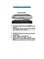
Hardware Configuration
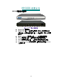
Hardware Description:
Power LED: Illuminates solid green when MH1000 is first
powered up. Start up takes up to one minute to complete.
Status LED: When LED light start glittering, it means the
system is under the status of booting. Around two minutes
when the LED light stop glittering, it means the system
is booting successful.
WAN 1/2 Port: To connect to the external router, DSL modem,
or Cable modem.
LAN Port: Connect to the intranet PCs.
DMZ Port: Connect to the company's server(s).
Console Port: 9-pin serial port connector for checking
MH1000 system setting and restore to the factory setting.
3

Software Configuration
STEP 1﹒Connect both the Administrator's PC and the LAN port of MH1000
to a hub or switch. And use a web browser to display the
configurations of the MH1000 (such as Internet Explorer or
Netscape). The default IP address of MH1000 is
http://192.168.1.1 with a subnet mask of 255.255.255.0.
Therefore, the IP address of the Administrator PC must be in the
range between 192.168.1.2 192.168.1.254
STEP 2﹒
After the new IP of Administrator's PC take effect, enable IE or Netscape
and connect to http://192.168.1.1 and it can use browser to set up the
parameter of MH1000.
The following table is a list of virtual IP
addresses. These addresses may not use WAN Real IP
address.
10.0.0.0 ~ 10.255.255.255
172.16.0.0 ~ 172.31.255.255
192.168.0.0 ~ 192.168.255.255
STEP 3﹒
4

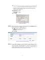
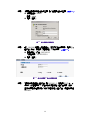
A pop-up screen will appear and prompt for a username and
password. A username and password is required to connect to
MH1000. Enter the default login username and password of
Administrator (FigureS-1).
Username: admin
Password: admin
Click OK.
FigureS-1 Login WebUI
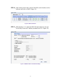
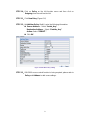
STEP 4﹒After entering the username and password, select Interface on the
left menu and click on LAN. (FigureS-2)
LAN: enter IP address 192.168.1.1
Netmask: 255.255.255.0
Click OK.
FigureS-2 IP Address and Netmask Setting
STEP 5﹒If new LAN IP Address is not 192.168.1.1, after clicking on OK, it
must change the System Manager’s IP Address to be at the same
subnet range as the new LAN IP. And enter the new LAN IP in
browser website field and reconnect MH1000 again.
5

STEP 6﹒After entering to the main system of MH1000, select Interface on the
left menu and click on WAN. (Figure S-3)
FigureS-3 WAN 1/2 Interface
STEP 7﹒WAN Interface 1 / 2: select the WAN 1/2 that needs to be set and
click Modify. Enter the IP address provided from ISP. (Figure S-4)
Figure S-4 WAN IP Address and Netmask Setting
6

STEP 8﹒Click on System function and click on Date/Time function in
Configure.
STEP 9﹒Enter the following setting in Date/Time setting:
Select Enable synchronize with an Internet time Server.
Set offset +8 hours from GMT
Enter the Server IP/Name: 133.100.9.2
Enter Update system clock every 360 minutes.
Click OK. (FigureS-5)
FigureS-5 Date/Time Setting
7

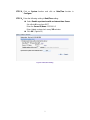
STEP 10﹒Click on Policy on the left function menu and then click on
Outgoing from the sub-function list.
STEP 11﹒Click New Entry (Figure S-6)
STEP 12﹒At Add New Policy WebUI, enter the following information:
Source Address – Select “Inside_Any”
Destination Address – Select “Outside_Any”
Action: Select “PERMIT ”
Click OK
Figure S-6 Add New Policy Setting
STEP 13﹒If MH1000 access control function is being required, please refer to
Policy and Address to add some settings.
8

繁體安裝
9

MH1000 硬體安裝
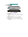
MH1000 硬體外部介面說明:
圖 H-1 MH1000 接孔、指示燈說明
Power LED:電源顯示
Status LED:當 LED 燈為開始閃爍時,表示系統正在開機狀態,
約兩分鐘後系統開機程序結束,當 LED 停止閃爍,表示系統己開
機成功。
WAN 1 / 2 Port:外部網路介面 1 / 2,與外部路由器連結。
LAN:內部網路介面,將企業內部的網路連結在此網路。
DMZ:非軍事區網路介面,將企業內的伺服器連結在此網路。
Console Port:9-pin 的串列埠接頭,主要的用途是查看 MH1000
系統環境參數。
10

MH1000 軟體設定
步驟1. 首先將系統管理員的電腦和MH1000 內部網路介面接到同一個HUB
或Switch,再使用瀏覽器 ( IE或 Netscape ) 連結至MH1000。
MH1000 內部網路介面的IP位址內定值為http://192.168.1.1,所以系
統管理員的電腦之IP位址必須是192.168.1.2至 192.168.1.254 其中
之一,子網路遮罩為 255.255.255.0。
步驟2. 當管理員的電腦和MH1000 的內部網路介面位址 屬於 192.168.1.0
網段的網路,開啟瀏覽器(IE 或 Netscape )連結至
http://192.168.1.1 。連上MH1000 的WebUI,即可開始使用瀏覽器
設定MH1000 的參數。
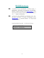
下列表格為標準虛擬 IP 位址範圍,不可使用外部真實 IP 位址。
10.0.0.0 ~ 10.255.255.255
172.16.0.0 ~ 172.31.255.255
192.168.0.0 ~ 192.168.255.255
11

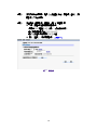
步驟3. 瀏覽器會詢問使用者名稱及密碼,輸入管理員名稱與密碼。
(如圖
S-1
)
使用者名稱:admin
密碼:admin
點選【確定】
圖 S-1 鍵入使用者名稱與密碼
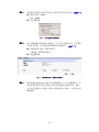
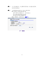
步驟4. 進入MH1000 軟體系統主畫面後,在左方的功能選項中,點選【介
面位址】功能,再點選【內部網路】次功能選項。
(如圖
S-2
)
內部網路 IP 位址:192.168.1.1
子網路遮罩:255.255.255.0
點選【確定】
圖 S-2 鍵入內部網路 IP 位址與子網路遮罩
步驟5. 如果新的內部網路介面位址不是 192.168.1.1。在點選【OK】後,必
須更改系統管理員的 IP 位址與新的內部網路介面位址為同一網段。
並在瀏覽器網址欄位輸入新的內部網路介面位址,再重新連結
MH1000。
12

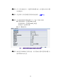
步驟 . 6 進入MH1000 軟體系統主畫面後,在左方的功能選項中,點選【介
面位址】功能,再點選【外部網路】次功能選項。
(如圖
S-3
)
圖 S-3 外部網路介面 1 / 2 介面
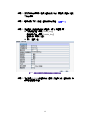
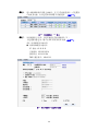
步驟7. 外部網路介面 1 / 2:點選需要設定的外部網路 1 / 2 ,
點選【修改】選項。鍵入由 ISP 所配發的 IP 位址
(如圖
S-4
)
(例:外部網路介面位址 1)
外部網路路介面位址 1:
IP 位址
:61.11.11.11
子網路遮罩:255.255.255.0
預設閘道:61.11.11.254
DNS 伺服器 1:168.95.1.1
圖 S-4 鍵入外部網路 IP 位址與子網路遮罩
13

步驟8. 在左方的功能選項中,點選【系統管理】功能,再點選【組態】【時
間設定】次功能選項。
步驟9. 在出現的【時間設定】視窗中,鍵入下列相關參數:
勾選【開啟與外部時間伺服器同步】
選擇與 GMT 相差【+8】小時。(依所在地決定)
輸入時間伺服器位址【133.100.9.2】
輸入系統自動更新時間【360】分鐘
按下【確定】,完成時間設定。
(如圖
S-5
)
圖 S-5 時間設定
14

步驟10. 在左方的功能選項中,點選【管制條例】功能,再點選【內部至外部】
次功能選項。
步驟11. 點選螢幕下方的【新增】管制條例功能按鈕。
(如圖
S-6
)
步驟12. 在出現的【新增管制條例】視窗中,鍵入下列相關參數:
來源網路位址:選擇【Inside_Any】
目的網路位址:選擇【Outside_Any】
管制動作:選擇【允許】
按下【確定】鈕。
圖 S-6 至管制條例功能設定來源網路位址與目的網路位址
步驟 . 13 如欲使用 MH1000 的管制功能,請在【位址表】和【管制條例】功
能項增加相關設定值。
15

简体安装
16

MH1000 硬件安装
MH1000 硬件外部接口说明:
图 H-1 MH1000 接孔、指示灯说明
Power LED:电源显示
Status LED:当 LED 灯为开始闪烁时,表示系统正在开机状态,
约两分钟后系统开机程序结束,当 LED 停止闪烁,表示系统己开
机成功。
WAN 1 / 2 Port:外部网络接口 1 / 2,与外部路由器连结。
LAN:内部网络接口,将企业内部的网络连结在此网络。
DMZ:非军事区网络接口,将企业内的服务器连结在此网络。
Console Port:9-pin 的串行埠接头,主要的用途是查看 MH1000
系统环境参数。
17

MH1000 软件设定
步骤1. 首先将系统管理员的计算机和MH1000 内部网络接口接到同一个
HUB或Switch,再使用浏览器 ( IE或 Netscape ) 连结至MH1000。
MH1000 内部网络接口的IP地址内定值为
http://192.168.1.1,所以系
统管理员的计算机之IP地址必须是 192.168.1.2至 192.168.1.254 其
中之一,子网掩码为 255.255.255.0。
步骤2. 当管理员的计算机和MH1000 的内部网络接口地址 属于
192.168.1.0 网段的网络,开启浏览器(IE或Netscape)连结至
http://192.168.1.1 。连上MH1000 的WebUI,即可开始使用浏览器
设定MH1000 的参数。
下列表格为标准虚拟 IP 地址范围,不可使用外部真实 IP 地址。
10.0.0.0 ~ 10.255.255.255
172.16.0.0 ~ 172.31.255.255
192.168.0.0 ~ 192.168.255.255
18

步骤3. 浏览器会询问使用者名称及密码,输入管理员名称与密码。
(如图
S-1
)
使用者名称:admin
密码:admin
点选【确定】
图 S-1 键入使用者名称与密码
步骤4. 进入 MH1000 软件系统主画面后,在左方的功能选项中,点选【接
口地址】功能,再点选【内部网络】次功能选项。
(如图
S-2
)
内部网络 IP 地址:192.168.1.1
子网掩码:255.255.255.0
点选【确定】
图 S-2 键入内部网络 IP 地址与子网掩码
步骤5. 如果新的内部网络接口地址不是 192.168.1.1。在点选【OK】后,必
须更改系统管理员的 IP 地址与新的内部网络接口地址为同一网段。
并在浏览器网址字段输入新的内部网络接口地址,再重新连结
MH1000。
19
ページが読み込まれています...
ページが読み込まれています...
ページが読み込まれています...
-
 1
1
-
 2
2
-
 3
3
-
 4
4
-
 5
5
-
 6
6
-
 7
7
-
 8
8
-
 9
9
-
 10
10
-
 11
11
-
 12
12
-
 13
13
-
 14
14
-
 15
15
-
 16
16
-
 17
17
-
 18
18
-
 19
19
-
 20
20
-
 21
21
-
 22
22
-
 23
23


