
CXD Amplifiers
User Manual
CXD4.2 — 4 Channel, 1600 W Amplifier
CXD4.3 — 4 Channel, 2500 W Amplifier
CXD4.5 — 4 Channel, 5000 W Amplifier
TD-000367-00-A
*TD-000367-00*

2
EN EN
TD-000367-00-A
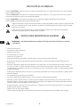
EXPLANATION OF SYMBOLS
The term “WARNING!” indicates instructions regarding personal safety. If the instructions are not followed the result may be bodily injury or death.
The term “CAUTION!” indicates instructions regarding possible damage to physical equipment. If these instructions are not followed, it may result in
damage to the equipment that may not be covered under the warranty.
The term “IMPORTANT!” indicates instructions or information that are vital to the successful completion of the procedure.
The term "NOTE" is used to indicate additional useful information.
The intent of the lightning flash with arrowhead symbol in a triangle is to alert the user to the presence of un-insulated "dangerous"
voltage within the product's enclosure that may be of sufficient magnitude to constitute a risk of electric shock to humans.
The intent of the exclamation point within an equilateral triangle is to alert the user to the presence of important safety, and operating
and maintenance instructions in this manual.
IMPORTANT SAFETY INSTRUCTIONS
WARNING!:
TO PREVENT FIRE OR ELECTRIC SHOCK, DO NOT EXPOSE THIS EQUIPMENT TO RAIN OR MOISTURE.
• Keep these instructions.
• Heed all warnings.
• Follow all instructions.
• Do not use this apparatus near water.
• Clean only with a dry cloth.
• Do not block any ventilation opening. Install in accordance with the manufacturer's instructions.
• Do not install near any heat sources such as radiators, heat registers, stoves, or other apparatus (including amplifiers) that produce heat.
• Do not defeat the safety purpose of the polarized or grounding-type plug. A polarized plug has two blades with one wider than the other. A
grounding type plug has two blades and a third grounding prong. The wide blade or the third prong are provided for your safety. If the provided
plug does not fit into your outlet, consult an electrician for replacement of the obsolete outlet.
• Protect the power cord from being walked on or pinched particularly at plugs, convenience receptacles, and the point where they exit from
the apparatus.
• Only use attachments/accessories specified by the manufacturer.
• Unplug this apparatus during lightning storms or when unused for long periods of time.
• Refer all servicing to qualified service personnel. Servicing is required when the apparatus has been damaged in any way, such as power-supply
cord or plug is damaged, liquid has been spilled or objects have fallen into the apparatus, the apparatus has been exposed to rain or moisture,
does not operate normally, or has been dropped.
• The appliance coupler, or the AC Mains plug, is the AC mains disconnect device and shall remain readily operable after installation.
• Adhere to all applicable, local codes.
• Consult a licensed, professional engineer when any doubt or questions arise regarding a physical equipment installation.

3
EN EN
TD-000367-00-A
FCC Statement
NOTE:
This equipment has been tested and found to comply with the limits for a Class A digital device, pursuant to Part 15 of the FCC
Rules. These limits are designed to provide reasonable protection against harmful interference when the equipment is operated in a
commercial environment. This equipment generates, uses, and can radiate radio frequency energy and, if not installed and used in
accordance with the instruction manual, may cause harmful interference to radio communications. Operation of this equipment in a
residential area is likely to cause harmful interference in which case the user will be required to correct the interference at his
own expense.
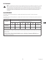
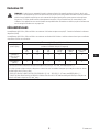
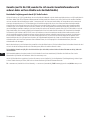
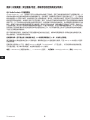
RoHS STATEMENT
The QSC CXD4.2, CXD4.3 and CXD4.5 amplifiers are in compliance with European Directive 2002/95/EC – Restriction of Hazardous
Substances (RoHS).
The QSC CXD4.2, CXD4.3 and CXD4.5 amplifiers are in compliance with “China RoHS” directives. The following chart is provided for product use in
China and its territories:
QSC CXD4.2, CXD4.3, and CXD4.5 Amplifiers
部件名称
(Part Name)
有毒有害物质或元素
(Toxic or hazardous Substances and Elements)
铅
(Pb)
汞
(Hg)
镉
(Cd)
六价铬
(Cr(vi))
多溴联苯
(PBB)
多溴二苯醚
(PBDE)
电路板组件
(PCB Assemblies)
X O O O O O
机壳装配件
(Chassis Assemblies)
X O O O O O
O: 表明这些有毒或有害物质在部件使用的同类材料中的含量是在 SJ/T11363_2006 极限的要求之下。
(O: Indicates that this toxic or hazardous substance contained in all of the homogeneous materials for this part is below the limit requirement
in SJ/T11363_2006.)
X: 表明这些有毒或有害物质在部件使用的同类材料中至少有一种含量是在 SJ/T11363_2006 极限的要求之上。
(X: Indicates that this toxic or hazardous substance contained in at least one of the homogeneous materials used for this part is above the
limit requirement in SJ/T11363_2006.)

4
EN EN
TD-000367-00-A
Warranty (USA only; other countries, see your dealer or distributor)
QSC Audio Products 3 Year Limited Warranty
QSC Audio Products, LLC (”QSC”) guarantees its products to be free from defective material and/or workmanship and will replace defective parts
and repair malfunctioning products under this warranty when the defect occurs under normal installation and use, provided the unit is returned to
our factory, one of our authorized service stations or an authorized QSC International Distributor via pre-paid transportation with a copy of proof
of purchase (i.e., sales receipt). This warranty provides that the examination of the return product must indicate, in our judgment, a manufacturing
defect. This warranty does not extend to any product which has been subjected to misuse, neglect, accident, improper installation, or where the
date code has been removed or defaced. QSC shall not be liable for incidental and/or consequential damages. This warranty gives you specific legal
rights. This limited warranty is freely transferable during the term of the warranty period. The warranty on QSC products is NOT VALID if the products
have been purchased from an unauthorized dealer/online e-tailer, or if the original factory serial number has been removed, defaced, or replaced in
any way. Damage to, or loss of any software or data residing on the product is not covered. When providing repair or replacement service, QSC will
use reasonable efforts to reinstall the product’s original software configuration and subsequent update releases, but will not provide any recovery or
transfer of software or data contained on the serviced unit not originally included in the product.
Customers may have additional rights, which vary from state to state or from country to country. In the event that a provision of this limited warranty is
void, prohibited or superseded by local laws, the remaining provisions shall remain in effect.
The QSC limited warranty is valid for a period of three (3) years from date of purchase in the United States and many (but not all)
other countries.
For QSC warranty information in countries other than the United States, contact your authorized QSC international distributor. A list of QSC
International distributors is available at www.qsc.com.
To register your QSC product online, go to www.qsc.com and select ”Product Registration”. Other questions regarding this warranty can be answered
by calling, e-mailing or contacting your authorized QSC distributor.
Phone: 1-800-854-4079 within US and Canada, +1-714-754-6175 international, Email: [email protected], Website: www.qsc.com.

5
EN EN
TD-000367-00-A
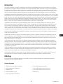
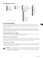
Introduction
Built for system integrators, the CXD series amplifiers provide multi-channel amplification with built-in DSP and enough power to drive wide varieties
of speaker systems with optimal energy efficiency. The CXD Series consists of three light-weight, 2RU, four-channel amplifiers with on-board DSP and
flexible channel combining as well as 70V and 100V direct drive. These amplifiers not only provide the power and processing to make your system
perform better, they offer outstanding efficiency ensuring that energy costs are kept to a minimum over the life of the installation.
CXD amplifiers feature Flexible Amplifier Summing Technology (FAST). Depending on the model, 1600, 2500, or 5000 Watts of total power can be
distributed across one to four outputs. In addition, the CXD4.3 and CXD4.5, can drive 70V or 100V speaker lines directly from any one or all of the four
outputs. This flexibility allows CXD Series amplifiers to drive (for example) two full-range, surface-mounted loudspeakers along with a subwoofer and
one 100 V distributed loudspeaker line; or a high-power subwoofer and a bi-amplified full-range loudspeaker; three 70V distributed loudspeaker lines
and a subwoofer; or a single very high-power channel to drive monster subwoofers.
The CXD Series amplifiers use QSC’s third-generation class-D power amp design in combination with a custom power stage utilizing a new output
device. In addition, CXD amplifiers employ the proven PowerLight power supply in conjunction with Power Factor Correction (PFC) which aligns the
current waveform with the AC mains voltage waveform. PFC enables the CXD Series amplifiers to draw current from the wall in a more efficient and
controlled manner resulting in very high power from a single standard AC breaker. Additionally, the CXD Series amplifiers offer multi-stage sleep
modes saving energy when possible without sacrificing performance. The result is an exceptionally powerful and flexible platform that offers low
weight and efficiency.
With four channels of amplification plus signal processing in just 2RUs, the CXD series replaces equipment taking up as much as three times
the rack-space.
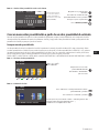
A single CXD Series amplifier is a capable and sophisticated loudspeaker processor. Integration of processing and amplification means that the DSP
knows exactly what the amplifier is doing so dynamics processing can be far more accurate and effective. This approach employs both RMS and Peak
Limiters that allow the amplifier and loudspeaker to produce more output without being pushed to distortion or destruction.
The on-board DSP offers four channels of cross-over filters, parametric EQ/Low-shelf/High-shelf, alignment delay and dynamics processing —
everything needed to optimize a loudspeaker system. Additionally when using QSC loudspeakers, CXD amplifiers provide Intrinsic Correction™, a
combination of filtering, limiting and loudspeaker knowhow that was first developed for QSC's WideLine line-array loudspeakers. Intrinsic Correction
compensates for the non-linearity in array and horn design resulting in exceptional performance.
The CXD also includes manufacturers' recommended tunings for the most popular passive loudspeakers. A system setup wizard helps you select the
right preset, or select one of the 20 configuration templates and create tunings that you can save in the user preset library.
With a dedicated front panel user interface, complete with LED meters and indicators, a 400 x 240 TFT color display, a rotary encoder and navigation
buttons, the CXD amplifiers provide an intuitive means to control the system.
Unpacking
There are no special unpacking instructions. You may want to keep the shipping material for the unlikely event that the amplifier should need
returning for service.
Package Contents
1. Quick-Start Guide TD-000350-00
2. Warning Information Sheet TD-000420-00
3. CXD Amplifier
4. IEC AC Power Cord
5. Euro-style Connector Plug, 3-pin (4)
6. Euro-style Connector Plug, 8-pin (1)
7. Euro-style Connector Plug, 3.5 mm, 2-pin (1)
8. Euro-style Connector Plug, 3.5 mm, 3-pin (1)
9. USB Cable (1)

6
EN EN
TD-000367-00-A
Features
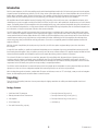
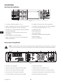
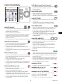
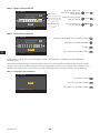
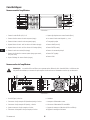
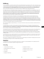
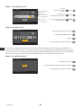
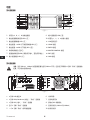
Amplifier Front Panel
— Figure 1 —
1
2
3
4
5
6
7
8
12
13
14
15
16
9
10
11
1. Output channels are labeled A, B, C, and D
2. Output Channel Mute Buttons and LEDs (Red)
3. Output Channel Limiter LEDs (Red)
4. Output Channel -10 dB Below Limiter Activation LEDs (Blue)
5. Output Channel -20 dB Below Clip LEDs (Blue)
6. Soft Power Button (Blue/Red)
7. Channel Select Buttons and LEDs (Amber for Input, Blue for Output)
8. Input Channel Clip LEDs (Red)
9. Input Channel Signal-Present LEDs (Blue)
10. Input channels are labeled 1, 2, 3, and 4
11. LCD Graphic Display
12. HOME Button
13. ENTER Button
14. MASTER CONTROL Knob
15. EXIT Button
16. GAIN Button
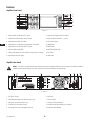
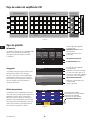
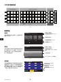
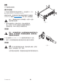
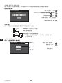
Amplifier Rear Panel
NOTE:
The CXD4.3, and CXD4.5 models have a different rear panel configuration than the CXD4.2 rear panel. The difference is that the
position of the fan and the eight-pin Euro-style connector and associated information are interchanged.
— Figure 2 —
CH AB
T1+
T3+
T2-
T4-
CH CD
T5+
T7+
T6-
T8-
CH ABC
T1
+
T3+
T5+
T2-
T4-
T6-
CH ABCD
T1
+
T3+
T5+
T7+
T2-
T4-
T6-
T8-
CH AB+CD
T1
+
T3+
T5-
T7-
CH C
+
D
T5+
T7-
CH A
+
B
T1+ T3-
BRIDGED
OUTPUTS TO SPEAKERS
CH A
CH D
CH C
CH B
+
+
+
+
-
-
-
-
T1
T4
T3
T2
T5
T8
T7
T6
SETTINGS CAN BE
CONFIGURED FOR
70V, 100V AND
200V DIRECT
OUTPUT.
PARALLEL CHANNEL
COMBINING APPLICATIONS
THIS PRODUCT SHOULD BE SUPPORTED ON ALL
FOUR CORNERS WHEN INSTALLED IN A RACK
USB
HEARTBEAT
GPO
GPI
1 4 5 6 7 8 102 93
1. USB Type B, four-pin
2. GPO/Heartbeat (output) Euro-style Connector, 3-pin
3. GPI (input) Euro-style Connector, 2-pin
4. Four three-pin Euro-style Connectors
5. One eight-pin Euro-style Loudspeaker Connector
6. Cooling fan
7. AC Power Switch
8. Locking IEC Power Connection
9. Rear Rack-mount Bracket (CXD4.3 and CXD4.5)
10. Front Rack-mount Brackets

7
EN EN
TD-000367-00-A
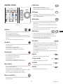
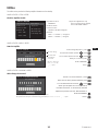
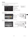
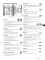
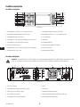
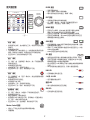
Amplifier Control
— Figure 3 —
OUTPUT
HOME
MASTER
CONTROL
-10
-20
LIM
SEL
MUTE
A
1
SEL
MUTE
B
2
SEL
MUTE
C
3
SEL
MUTE
D
4
CLIP
SIG
INPUT
ENTER
EXIT
GAIN
Off Mode
• Rear power switch is off, the amplifier is not operable. The power
switch is the AC Mains disconnect.
• The power button is not illuminated.
• Turn the power switch to on. The amplifier enters the mode it was in
when power was removed. The power button is illuminated based on
the mode.
• If GPI is enabled, the Off Mode button is disabled.
Run Mode
• From Standby or Mute All modes, press and release the power button
on the front panel.
• The power button is illuminated blue.
• The amplifier is fully operable; audio can pass.
• If GPI is enabled, the Run Mode button is disabled.
Standby Mode
• From Mute All or Run modes, press and hold the power button on
the front panel for two to three seconds.
• The power button illuminates solid red.
• The front panel LCD is off.
• The amplifier is not operable; audio will not pass.
• If GPI is enabled, the Standby Mode button is disabled.
Mute All Mode
• From the Run Mode, quickly press and release the power button.
• The power button flashes red.
• The outputs are muted and amplifiers are off.
• The front panel and DSP functionality are fully operable. Any changes
you make are saved and take effect in the Run Mode.
• If GPI is enabled, the Mute All Mode button is disabled.
Master Control Knob
• Scrolls up/down and right/left to select menu items and parameters
• Adjusts parameters
ENTER Button
• Navigates into the menu structure
• Enters the edit mode for adjusting parameters
• Confirms the changes you make, and exits the edit mode.
EXIT Button
• Navigates out of the menu structure and parameter selection.
• In the edit mode, pressing EXIT reverts the value back to its prior
state, and exits the edit mode.
HOME Button
• If you are on the Home screen, pressing HOME displays the alternate
Home screen. Pressing HOME again returns you to the primary
Home screen.
• If you are on a navigation screen, pressing HOME takes you to the
home screen.
• If you are on an edit screen, pressing HOME will confirm any value
being edited and take you to the Home screen.
GAIN Button
• Pressing the GAIN button from any screen takes you to the output
gain screen for the most recently accessed output channel.
• Pressing GAIN again confirms the gain change and returns to the
screen you were on when you pressed GAIN.
• The Gain button illuminates green when selected.
SEL Buttons
• Use these buttons to navigate between input channels or output
channels. For example, if you are adjusting output gain on channel A,
pressing the channel B SEL button takes you to the gain adjustment
for channel B.
• The SEL buttons are active only when the LCD screen is on an input
or output parameter adjustment screen.
• The SEL buttons illuminate blue for output channels, and amber for
input channels.
LIM LEDs
• Illuminates red when the Limiter is engaged.
-10 and -20 LEDs
• Indicates the output level of the channel.
CLIP LEDs
• Illuminates red when the input signal is being clipped.
SIG LEDs
• Illuminates blue when a signal is present.
ENTER
EXIT
HOME
GAIN GAIN
SEL SEL
LIM
-10 & -20
CLIP
SIG

8
EN EN
TD-000367-00-A
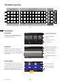
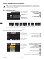
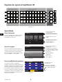
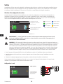
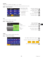
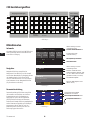
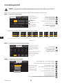
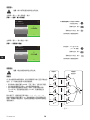
CXD Amplifier Signal Flow
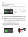
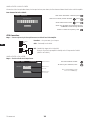
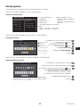
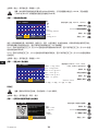
Screen Types
— Figure 5 —
Informational
Informational screens, like the HOME screen, are
designed to provide you with a good amount of
useful information at a glance.
F1: A B C D
Full
+1.5 dB
A - FR
+1.5 dB
C - FR
Full
+1.5 dB
D - FR
Full
121 V 7.2 AAC Voltage: AC Current:
Home (Press HOME for more information)
+3.5 dB
B - FR
Full
Amp Status:
OK
Preset # and Configuration
Location and breadcrumbs
Channel Configuration
and Gain
AC Voltage and Current
Amplifier Status
— Figure 6 —
Preset Recall and Save
Menu
PRESETS
INPUT S
F1: A B C D
Preset # and Configuration
Location and breadcrumbs
Current Menu Selection
Empty area indicates no
selections above (CCW).
Next Menu selection below
(CW)
Navigational
Navigational screens provide the means to move
around and select menu items. Use the Master
Control knob, ENTER and EXIT buttons for navigation.
This is an example of one type of navigational screen,
there are others.
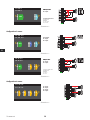
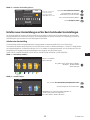
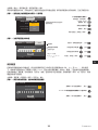
— Figure 7 —
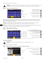
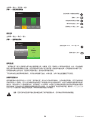
Parameter Editing
Parameter editing screens allow you to select, edit,
and confirm changes for various system parameters.
Use the ENTER button to edit and confirm changes
to parameters. Use the Master Control knob to select
parameter, and make adjustments. Use the EXIT
button to exit the edit mode without saving changes.
Gain
-7.0 dB
Gn/Pol
F1: A B C D
Polarity
POL+
Output
A
20 dB
-60 dB
Gain
-7.0 dB
Parameter being edited
Parameter not selected
Parameter selected
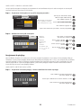
— Figure 4 —
Input Settings Output Processing
Gain
Gain
Gain
Gain
1
4
3
2
Mute
Mute
Mute
Mute
Gain /
Polarity
Gain /
Polarity
Gain /
Polarity
Gain /
Polarity
Low-
pass
Filter
Mixer
Mixer
Mixer
Mixer
Sensitivity
Switch
Sensitivity
Switch
Sensitivity
Switch
Sensitivity
Switch
Sensitivity
Switch
Sensitivity
Switch
A/D
A/D
A/D
A/D
Meter
Meter
Meter
Meter
5-Band
PEQ
5-Band
PEQ
5-Band
PEQ
5-Band
PEQ
Delay
Delay
Delay
Delay
Meter
Meter
Meter
Meter
D/A
D/A
D/A
D/A
Crossover
Button
Actuated
Amp Config.
A
D
B
C
Set by
Preset or Wizzard
RMS
Peak
Limiter
RMS
Peak
Limiter
RMS
Peak
Limiter
RMS
Peak
Limiter
Low-
pass
Filter
Low-
pass
Filter
Low-
pass
Filter
High-
pass
Filter
High-
pass
Filter
High-
pass
Filter
High-
pass
Filter

9
EN EN
TD-000367-00-A
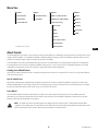
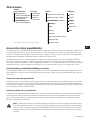
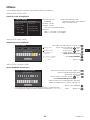
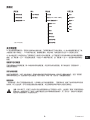
Menu Tree
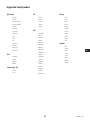
*For QSC Line Arrays only
Presets
Preset Wizard
Preset Recall
Preset Save
Inputs
Input Sensitivity
Input Gain
Outputs
Mixer w/Noise & Tone
Mode (Lo-Z, 70V, 100V)
Save Speaker
Load Speaker
Array Correction*
Limiter
Delay
PEQ
Crossover
Spkr Processing
Utilities
Display
Status
Amp ID
Password
Lockout
GPIO
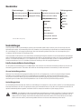
About Presets
The CXD amplifiers are preset driven. In order to get the most out of the amplifiers, an understanding of how presets work is essential. A Preset, in the
context of the CXD amplifiers, is a combination of amplifier configuration (inputs and outputs), DSP and loudspeaker assignments. When a preset is
recalled it can change the output routing and wiring and/or any of the DSP settings.
The CXD amplifiers come with 20 unchangeable factory presets, and 50 user-defined presets. The factory presets are designed to be starting points
for creating the presets you need for your particular installation. Factory presets F1: thru F9: have no DSP or loudspeaker assignments, only output
configurations. Factory presets F10: thru F20: include basic settings along with the output configurations.
Creating User-defined Presets
A preset can be created in two ways, the first is to modify an existing preset, then save this as a new preset. The second is to use the Preset Wizard to
create a Preset from scratch.
Save As a New Preset
After selecting a starting preset, navigate through the Input and Output menus to select and modify the parameters needed for your system. After
modifying the parameters for each channel, return to the Preset menu and save your work. If you started with a user-defined preset, you can update
the preset you started with using the SAVE function or, you can use the SAVE AS function.
Preset Wizard
The Preset Wizard simplifies the preset creation process, and allows you to create a preset from the ground up. The Preset Wizard provides a
mechanism for you to select the desired power and load. Based on these selections, the best amplifier configuration is selected and you are then
allowed to select and assign loudspeakers to each output.
NOTE:
By default, all 50 of the user-defined presets are configured the same as factory preset F1. Either method described above
"overwrites" some existing preset. The main difference is the SAVE function overwrites only the preset number you started with, and the
SAVE AS function allows you to save to a different user preset number and change the name.

10
EN EN
TD-000367-00-A
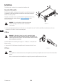
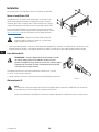
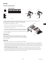
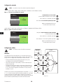
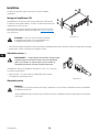
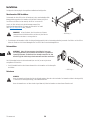
Installation
The following steps are written in the recommended installation order.
Mount the CXD Amplifier
The CXD Series amplifiers are designed to be mounted in a standard rack-mount unit.
The amplifiers are 2RU high, the CXD4.3 and CXD4.5 are 381 mm (15 in) deep, the
CXD4.2 is 229 mm (9 in) deep.
Depending on the depth of your rack, the Rear Rack Ear Support kit (FG-000031-00)
may be required for rack mounting. Refer to http://qsc.com/products/ under
Accessories for details.
CAUTION!:
Be sure that nothing is blocking the front or rear
ventilation openings, and that each side has a minimum of
2 cm clearance.
1. Use the proper fastening hardware (not included) to secure the amplifier in the rack. The CXD4.3 and CXD4.5 have four front and four rear
mounting tabs. The CXD4.2 has four front mounting tabs.
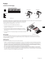
AC Mains
WARNING!:
When the AC Power is on, there is a potential of having
dangerous voltage at the output terminals on the rear of the amplifier. Use
caution not to touch these contacts. Turn off the AC Mains disconnect switch
prior to making any connections.
The CXD amplifiers have a Universal power supply 100 – 240 VAC, 50 – 60 Hz, with an IEC
locking connector.
1. Connect the IEC AC cable between the amplifier rear AC connector and the AC source.
AC Power
NOTE:
If the amplifier has no audio for fifteen minutes, the amplifier stops switching. The amplifier returns to the Run mode the instant audio is
present.”
When you remove power from the amplifier, then re-apply the power, the amplifier returns to its last state.
— Figure 8 —
— Figure 9 —

11
EN EN
TD-000367-00-A
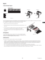
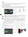
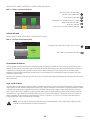
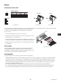
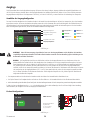
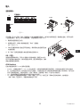
Inputs
Connect the Audio Inputs
— Figure 10 —
HEARTBEAT
GPO
GPI
USB
ROUTABLE INPUTS
21 43
— Figure 11 —
Unbalanced
— Figure 12 —
Balanced
There are four three-pin Euro-style connectors labeled 1 through 4 providing the audio inputs on the CXD Amplifiers. A single input can be mixed to
one or a combination of outputs. You can use from one to four of the inputs. The inputs
are 10 kΩ balanced or unbalanced, with a sensitivity of either +4 or +14 dBu.
1. Make sure your audio source devices are powered off.
2. Connect the input source wires to the Euro-style connectors as shown. (Figure 11 and
Figure 12)
3. The CXD Series has the capability of routing the inputs to different outputs. Be sure that
the connections you make here match the configuration of the amplifier.
4. Plug the Euro-style audio connectors into the appropriate inputs on the rear of
the amplifier.
USB (Optional)
The USB cable (supplied) connects to a Mac or PC for use with the Amplifier Navigator
software. You can update the amplifier firmware, save and deploy configuration files, and
more. Refer to the Amplifier Navigator online help for details.
GPIO/Heartbeat
There are two 3.5 mm Euro-style connectors on the rear of the amplifier.
• Heartbeat — The heartbeat output supplies a square wave signal of 1 Hz @ 3.3 V. This signal can connect to a life-safety system to monitor the
go/no-go condition of the amplifier. The amplifier must be completely incapable of producing output for the heartbeat signal to stop. A missing
heartbeat alerts the life-safety system of the disabled condition. A user-initiated condition such as muting the outputs, placing the amplifier in
Standby mode, or placing the amplifier in Mute All mode, does not stop the heartbeat.
• GPO — The functionality of this general purpose output pin has not been determined as of the release of this document.
• GPI — This input is used to put the amplifier into Standby from a remote location. When the GPI is enabled in the Utilities menu, then is shorted to
ground, the amplifier goes into the Standby mode. The front-panel power button is disabled when GPI is enabled.
— Figure 13 —
+
-
+
-
+
-
+
-

12
EN EN
TD-000367-00-A
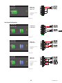
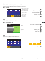
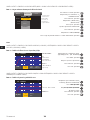
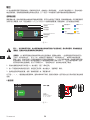
Outputs
The CXD amplifiers have four configurable outputs. You can set the power, combine outputs (bridged and parallel), and adjust the DSP for each
output. When the output configuration of the amplifier changes, the output terminals, controlled by relays, change accordingly. Use the diagrams
shown in Figure 15 thru Figure 23 as a reference for wiring the loudspeakers.
Select the Output Configuration
The first step in configuring your amplifier is to select a Preset based on the loudspeakers being connected to the amplifier. You can use a factory
preset, and then adjust the parameters as needed, then save the configuration as a user-defined preset. In addition, you can use the "Preset Wizard"
on page 16 to create presets from the ground up. When the configuration is changed, all four channels are automatically muted.
— Figure 14 —
F1: A B C D
F7: ABC D
M
ABC
M
D
Input number
Sub-woofer
Mid-Frequency
Full Range
High-Frequency
Low-Frequency
Current Configuration
Selected Configuration
Input Mixer
Output Configuration
Frequency Range color
Frequency Range Color Codes
WARNING!:
When the AC Power is on, there is a potential of having dangerous voltage at the output terminals on the rear of
the amplifier. Use caution not to touch these contacts. Turn off the AC Mains disconnect switch prior to making any connections.
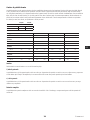
IMPORTANT:
QSC recommends that you connect jumpers between the output terminals where the terminals are the same points
electrically. When configuring your amplifier, there are going to be some loudspeaker connections that are noted as being "electrically
the same point". In Figure 15, all four channels are in parallel with the "electrically the same" terminals jumpered as recommended. In
addition, you can connect one loudspeaker to each of the four output channel terminals, and the four loudspeakers are in parallel; in this
case you would not need to jumper the terminals. You can connect four loudspeakers to one channel's output terminals (i.e. T1 and T2),
and the four loudspeakers are in parallel; in this case you would want to jumper the terminals. In all of the examples below, the
"electrically the same" terminals are shown with jumpers installed.
1. Turn the AC Mains power switch on the back of the amplifier to on. The amplifier starts in the Run mode.
2. Press and release the front-panel power button. The button flashes red, the amplifier is in Mute All mode.
3. Select the configuration appropriate for your loudspeakers, using either Preset Recall, or the Preset Wizard.
The following is a list of configurations for 1, 2, 3, and 4-channel outputs. This is not an exhaustive list, but is intended to give you an idea of what is
available and how the outputs would be wired.
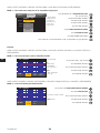
One-Channel Configurations
— Figure 15 —
F9: ABCD
F9: ABCD
ABCD Parallel
M
ABCD
The following are electrically
the same point
T1+, T3+, T5+, and T7+
T2-, T4-, T6-, and T8-

13
EN EN
TD-000367-00-A
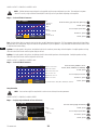
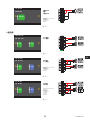
— Figure 16 —
F8: AB+CD
F8: AB+CD
AB Parallel
Bridged with
CD Parallel
The following are electrically
the same point
T1+and T3+
T5- and T7-
M
AB+CD
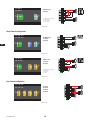
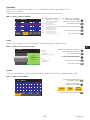
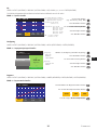
Two-Channel Configurations
— Figure 17 —
F6: A+B C+D
F6: A+B C+D
A+B Bridged
C+D Bridged
A+B
C+D
M M
— Figure 18 —
F5: AB C+D
F5: AB C+D
AB Parallel
C+D Bridged
AB
C+D
M M
The following are electrically
the same point
T1+ and T3+
T2- and T4-
— Figure 19 —
F4: AB CD
F4: AB CD
The following are electrically
the same point
T1+ and T3+
T5+ and T7+
T2- and T4-
T6- and t8-
AB Parallel
CD Parallel
AB
CD
M M

14
EN EN
TD-000367-00-A
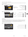
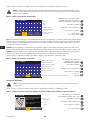
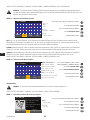
— Figure 20 —
F7: ABC D
F7: ABC D
ABC
D
M M
The following are electrically
the same point
T1+, T3+, and T5+
T2-, T4-, and T6-
ABC Parallel
D Single
Three-Channel Configurations
— Figure 21 —
F3: A+B C D
F3: A+B C D
A+B Bridged
C Single
D Single
A+B C D
M M M
— Figure 22 —
F2: AB C D
F2: AB C D
AB Parallel
C Single
D Single
M
AB
M
C
M
D
The following are electrically
the same point
T1+ and T3+
T2- and T4-
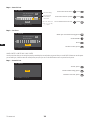
Four-Channel Configuration
— Figure 23 —
F1: A B C D
F1: A B C D
A Single
B Single
C Single
D Single
M M
A B
M
C
M
D

15
EN EN
TD-000367-00-A
Connect the Loudspeakers
WARNING!:
When the AC Power is on, there is a potential of having
dangerous voltage at the output terminals on the rear of the amplifier. Use
caution to not touch these contacts. Turn off the AC Mains disconnect switch
prior to making any connections.
1. Turn the AC Mains power switch, on the back of the amplifier, to OFF.
2. Connect the loudspeaker wiring to the 8-pin Euro-style connector. Refer to Figure 15
thru Figure 23. When combining channels, QSC recommends that you connect jumpers
between the electrically same output terminals. Refer to Figure 15 and the WARNING
above the figure.
3. Install the Euro-style connector onto the rear of the amplifier as shown in Figure 24.
4. Use a Phillips screwdriver to secure the connector.
AC Power On
After connecting the outputs to the loudspeakers, you may turn the amplifier on.
1. Make sure the output gain settings for all audio-source devices (CD Players, Mixers, Instruments, etc.) at the lowest output (max attenuation).
2. Turn on all audio sources.
3. Turn the AC Mains power switch on the back of the amplifier to ON. The amplifier starts in the state it was in when power was removed.
4. You can now bring up the outputs of your audio sources.
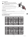
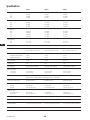
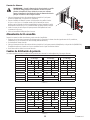
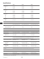
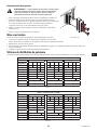
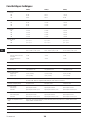
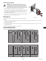
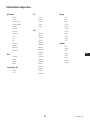
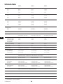
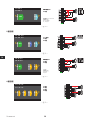
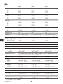
Power Distribution Charts
The following charts show the maximum power output for each channel in each configuration, and under different loads.
CXD 4.3 — Total Power: 2500W
8Ω Load 4Ω Load 2Ω Load
Configuration
A B C D A B C D A B C D
4 CH (A B C D) 625 625 625 625 650 650 650 650 600 600 600 600
3 CH (AB C D) 1000 625 625 1200 650 650 1200 600 600
3 CH (A+B C D) 1250 625 625 1150 650 650 625 600 600
2 CH (AB CD) 1000 1000 1200 1200 1200 1200
2 CH (AB C+D) 1000 1250 1200 1150 1200 625
2 CH (A+B C+D) 1250 1250 1150 1150 625 625
2 CH Alt (ABC D) 1100 625 2000 650 2500 600
1 CH (ABCD) 1100 2100 2500
1 CH (AB+CD) 2500 2370 2230
— Table 1 —
CXD 4.5 — Total Power: 5000W
8Ω Load 4Ω Load 2Ω Load
Configuration A B C D A B C D A B C D
4 CH (A B C D) 1150 1150 1150 1150 1250 1250 1250 1250 625 625 625 625
3 CH (AB C D) 1200 1150 1150 2250 1250 1250 2100 625 625
3 CH (A+B C D) 2250 1150 1150 1150 1250 1250 625 625 625
2 CH (AB CD) 1200 1200 2250 2250 2100 2100
2 CH (AB C+D) 1200 2250 2250 1150 2100 625
2 CH (A+B C+D) 2250 2250 1150 1150 625 625
2 CH Alt (ABC D) 1150 1150 2400 1250 4100 625
1 CH (ABCD) 1150 2300 4200
1 CH (AB+CD) 4200 4250 2250
— Table 2 —
— Figure 24 —

16
EN EN
TD-000367-00-A
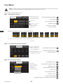
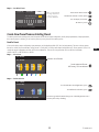
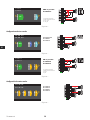
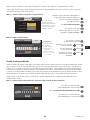
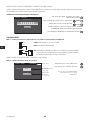
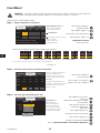
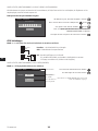
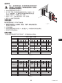
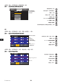
Preset Wizard
NOTE:
The power levels shown in this procedure are taken from the CXD4.3 unless indicated otherwise. CXD4.2 will show less power
and CXD4.5 will show greater power. For complete details refer to the "Specifications" on page 28.
HOME > PRESETS > PRESET WIZARD > ENTER
Step 1 —
Adjust Impedance and Power
OUTPUTS SPEAKERS SAVE
A B C D
Output:
8.0 - - - - - -
Imped:
625 - - - - - -
Power:
Remaining Power Available: 1875 W
Enter Load Profile (Impedance and Power)
Default = 8 Ω
Default = min. for amp
Adjust Impedance based on
the total loudspeaker load
connected to the channel.
Scroll to select (Imped or Power)
To edit, press
ENTER
Repeat for remaining
output channels
To confirm, press
ENTER
Turn to adjust parameter
Impedance and Power
are dynamically linked
for adjustments.
— Figure 25 —
Possible Output Mode Combinations using the Preset Wizard
Modes: A B = Separate Channels / A+B = Bridge Mode / AB = Parallel Mode
* Precentages are used to represent the power for different amplifier models.
- - -
B
25%
A
- - -
25%
D
- - -
25%
C
- - -
25%
AB
- - -
50%
D
- - -
25%
C
- - -
25%
CD
- - -
50%
AB
- - -
50%
A+B
- - -
50%
D
- - -
25%
C
- - -
25%
D
- - -
25%
ABC
- - -
75%
ABCD
- - -
100%
AB + CD
- - -
100%
A+B
- - -
50%
C+D
- - -
50%
*
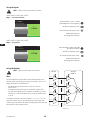
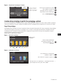
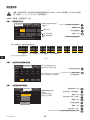
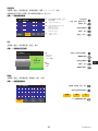
Step 2 —
Select Output Channel for Speaker Assignment
OUTPUTS SPEAKERS SAVE
Assign
AssignAssign
Output:
A DCB
Imped:
8.0 8.08.08.0
Spkr:
- - - - - - - -- - - -- - - -
Assign
Power:
625 625625625
Loudspeaker assignment is optional,
you can assign a loudspeaker to one
or more channels, or none at all.
When you are finished setting
the Impedance and Power for
each output, continue to scroll
to access the SPEAKERS tab.
To Assign a loudspeaker, press
Continue to Step 3.
Scroll to select Output channel
ENTER
Step 3 —
Select Speaker Type for Channel
OUTPUTS SPEAKERS SAVE
Output:
A
ASSIGN
2-Way LF
Speaker:
80 Hz
Band:
WL2102 BiLFNS
Filter:
Scroll to select a Speaker model
To edit Speaker, press
ENTER
Scroll to select (Band, Filter)
To confirm, press
ENTER
Turn to adjust parameter
ENTER
To edit, press
To confirm, press
ENTER
Band and Filter
selections are based on
the Speaker you select.
You must select a
loudspeaker before
selecting Band and Filter.
Scroll to select ASSIGN
ENTER
To assign the speaker to the output channel, press

17
EN EN
TD-000367-00-A
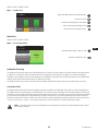
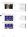
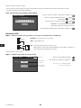
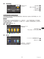
Step 4 —
Save Wizard Preset
Edit preset number or press EXIT
User Preset Number:
21
SAVE
New Preset Name
C o n f i g - A
OUTPUTS SPEAKERS SAVE
Scroll to the Save screen
To edit User Preset number, press
ENTER
When you have finished
selecting loudspeakers,
continue to scroll to
access the SAVE tab.
Turn to adjust parameter
To confirm, press
ENTER
Create New Preset from an Existing Preset
To create a preset from an existing preset, recall the preset with the desired output configuration, modify the Input parameters, Output parameters,
then save the preset. In addition, you can save the preset as you are going thru the creation process.
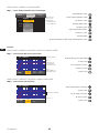
Recall a Preset
A Preset includes the output configuration, input parameters, and loudspeaker profiles (DSP, load, and assignments). There are 20 factory presets
that can be recalled, but not overwritten. Factory presets F1: Config thru F9: Config contain output configurations only. Factory presets F10: thru F20:
contain the output configurations and basic DSP for the configurations. There are 50 user presets that can be recalled and overwritten.
HOME > PRESETS > PRESET RECALL > ENTER
Step 1 —
Select Preset
A B C D
M M M M
F1: A B C D
F1: A B C D
Indicates more Presets
Input Sub MF FullHFLF
Scroll to desired Preset
20 Factory, 50 User-defined
Step 2 —
Confirm Selection
F1: A B C D
F18: 3-Way
Press ENTER to confirm selection
A+B
C D
M M M
The message at the bottom changes to: “Recalling Preset now...”
You may hear relays clicking
To conrm the selection, press
ENTER
To select the Preset conguration, press
ENTER

18
EN EN
TD-000367-00-A
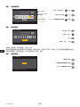
Set up the Inputs
NOTE:
Changes made to input levels are in real time.
HOME > INPUTS > INPUT SENS > ENTER
Step 1 —
Select Input Sensitivity
F1: A B C D
Inputs > Input Sens
INPUT SENS +14 dBu
Press ENTER to confirm
Input
1
Scroll to select (+14 or +4 dBu)
(The background turns to green.)
To confirm selection, press
ENTER
SEL
To move to the next input, press
Repeat procedure for
remaining input channels.
HOME > INPUTS > INPUT GAIN > ENTER
Step 2 —
Set Input Gain
F1: A B C D
Inputs > Input Gain
INPUT GAIN -11.8 dB
Press ENTER to confirm
Input
1
Scroll to select (-100 thru 20 dB)
(0.1 dB increments)
ENTER
To confirm selection, press
SEL
To move to the next input, press
Repeat procedure for
remaining input channels.
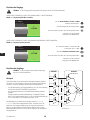
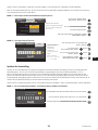
Set up the Outputs
NOTE:
Changes made to outputs are in real time.
Mixer
The CXD amplifiers are equipped with an internal mixer that allows you to
adjust the signals from each input to each of the four outputs. Figure 26 is a
diagram of the Mixer for Output Channel A.
• The default setting for the Input Gain is 0.0 dB, and is set in the
INPUTS section.
• Each output channel has four inputs, each controlled by a Mixer Gain.
• The Input Gain and Mixer Gain are cumulative. For example, if you set the
Input Gain to +2.0 dB, and the Mixer Gain to -5.0 dB, the resulting output
is -3.0 dB
As a default one channel is mixed to each output: 1 - A, 2 - B, 3 - C, 4 - D, all
other input channels are set to -100. Adjusting an Input Gain changes that
channel's input to the mixers of all channels. Changing a Mixer Gain affects only
that input for the selected output channel.
— Figure 26 —
Input 1
Input 2
Input 3
Input 4
Output
A
Output Mixers
B
D
C
Output Mixers
B
D
C
Output Mixers
B
D
C
Output Mixers
B
D
C
INPUTS OUTPUT
MIXER A
0.0 dB
-100 dB
-100 dB
-100 dB
0.0 dB
0.0 dB
0.0 dB
0.0 dB

19
EN EN
TD-000367-00-A
HOME > OUTPUTS > MIXER > ENTER
Step 1 —
Set Mixer Gains
F1: A B C D
Output
A
MIXER
Adjust the Mixer Gain for the selected Input
After confirming all settings, press
EXIT
To confirm, press
ENTER
Scroll to remaining Inputs and repeat
Input 1
4.2
Input 2
-100.0
Input 3
2.7
Input 4
-100.0
SEL
To move to the next output, press
Mode Select
HOME > OUTPUTS > MODE > ENTER
Step 2 —
Select the Output Mode
F1: A B C D
Outputs > Mode
MODE SELECT Mode:
Press ENTER to confirm
Output
A
Low-Z, 70V, 100V
Low-Z
Scroll to select Low-Z, 100V, or 70V
ENTER
To confirm selection, press
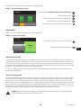
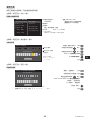
Loudspeaker Processing
The Speaker Processing section allows you to make adjustments to the Crossover, EQ, Delay, Limiter, and QSC Array details for each output channel.
In addition, you can load a pre-defined loudspeaker then make any adjustments needed, and save the changes as a user-defined loudspeaker.
Depending on the loudspeaker selection, various parameters are not available for adjustment. When you make adjustments, you are making them in
real time. If audio is passed while making changes, it is affected by the change.
The following instructions are not all in menu order, and all are optional. Repeat the following procedure for each output channel as necessary.
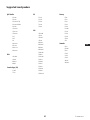
Load Speaker Profile
A loudspeaker profile includes all the DSP and loudspeaker characteristics available in the SPKR PROC section. When you LOAD a loudspeaker, you
are loading all of the DSP and characteristics of that loudspeaker. You can start by loading a loudspeaker and then make modifications and save your
new profile, or you can build the profile without loading a loudspeaker, and then save it as a new profile. If you load a QSC loudspeaker, the amplifier
is set for that specific loudspeaker and some parameters may be locked out because they are set to their optimal value by the Intrinsic Correction
Calculator, and should not be adjusted. The CXD comes with a number of supported loudspeakers from other manufacturers. Refer to the list under
"Supported Loudspeakers" on page 27. There may be additions to this list in the futrue that can be loaded with firmware updates.
NOTE:
If you make changes to any of the loudspeaker processing parameters, and then LOAD a loudspeaker profile, all the changes
you made are overwritten.

20
EN EN
TD-000367-00-A
HOME > OUTPUTS > SPKR PROC > LOAD SPKR > ENTER
Step 1 —
Load an Existing Loudspeaker for the Selected Output
ABOUT SPEAKERS LOAD
Output:
A
CONFIRM
2-Way LF
Speaker:
80 Hz
Band:
WL2102 BiLFNS
Filter:
Band and Filter
selections are
displayed and
constrained based
on the loudspeaker.
Scroll to select Speaker model
To edit Speaker, press
ENTER
Scroll to (Band, Filter)
To confirm, press
ENTER
Adjust selected parameter
ENTER
To adjust, press
To confirm, press
ENTER
Scroll to LOAD
ENTER
To Load the speaker profile to the selected output, press
Crossover
HOME > OUTPUTS > SPKR PROC > CROSSOVER > HIGH-PASS (OR LOW-PASS) > ENTER
Step 1 —
Set the Crossover High- and/or Low-pass filters
Freq
70.0
HPF
F1: A B C D
Type
BWrth
Output
A
20 dB
-60 dB
Slope
24dB/oct
Type:
• Butterworth
• Linkwitz-Riley,
• Bessel-Thomson
Slope:
6dB to 48dB/oct
depending on Type
Freq: 20 - 20 kHz
Scroll to select (Freq, Type, Slope)
Turn to adjust parameter
ENTER
To edit, press
To confirm, press
ENTER
EXIT
To exit, press
HOME > OUTPUTS > SPKR PROC > CROSSOVER > GAIN/POL > GAIN > ENTER
Step 2 —
Set the Crossover Gain and Polarity
Gain
-5.5 dB
Gn/Pol
F1: A B C D
Polarity
POL +
Output
A
20 dB
-60 dB
+
Gain -100 to +20 dB
–
Scroll to select (Gain or Polarity)
Turn to adjust parameter
ENTER
To edit, press
To confirm, press
ENTER
EXIT
To exit, press
Polarity + or -
ページが読み込まれています...
ページが読み込まれています...
ページが読み込まれています...
ページが読み込まれています...
ページが読み込まれています...
ページが読み込まれています...
ページが読み込まれています...
ページが読み込まれています...
ページが読み込まれています...
ページが読み込まれています...
ページが読み込まれています...
ページが読み込まれています...
ページが読み込まれています...
ページが読み込まれています...
ページが読み込まれています...
ページが読み込まれています...
ページが読み込まれています...
ページが読み込まれています...
ページが読み込まれています...
ページが読み込まれています...
ページが読み込まれています...
ページが読み込まれています...
ページが読み込まれています...
ページが読み込まれています...
ページが読み込まれています...
ページが読み込まれています...
ページが読み込まれています...
ページが読み込まれています...
ページが読み込まれています...
ページが読み込まれています...
ページが読み込まれています...
ページが読み込まれています...
ページが読み込まれています...
ページが読み込まれています...
ページが読み込まれています...
ページが読み込まれています...
ページが読み込まれています...
ページが読み込まれています...
ページが読み込まれています...
ページが読み込まれています...
ページが読み込まれています...
ページが読み込まれています...
ページが読み込まれています...
ページが読み込まれています...
ページが読み込まれています...
ページが読み込まれています...
ページが読み込まれています...
ページが読み込まれています...
ページが読み込まれています...
ページが読み込まれています...
ページが読み込まれています...
ページが読み込まれています...
ページが読み込まれています...
ページが読み込まれています...
ページが読み込まれています...
ページが読み込まれています...
ページが読み込まれています...
ページが読み込まれています...
ページが読み込まれています...
ページが読み込まれています...
ページが読み込まれています...
ページが読み込まれています...
ページが読み込まれています...
ページが読み込まれています...
ページが読み込まれています...
ページが読み込まれています...
ページが読み込まれています...
ページが読み込まれています...
ページが読み込まれています...
ページが読み込まれています...
ページが読み込まれています...
ページが読み込まれています...
ページが読み込まれています...
ページが読み込まれています...
ページが読み込まれています...
ページが読み込まれています...
ページが読み込まれています...
ページが読み込まれています...
ページが読み込まれています...
ページが読み込まれています...
ページが読み込まれています...
ページが読み込まれています...
ページが読み込まれています...
ページが読み込まれています...
ページが読み込まれています...
ページが読み込まれています...
ページが読み込まれています...
ページが読み込まれています...
ページが読み込まれています...
ページが読み込まれています...
ページが読み込まれています...
ページが読み込まれています...
ページが読み込まれています...
ページが読み込まれています...
ページが読み込まれています...
ページが読み込まれています...
ページが読み込まれています...
ページが読み込まれています...
ページが読み込まれています...
ページが読み込まれています...
ページが読み込まれています...
ページが読み込まれています...
ページが読み込まれています...
ページが読み込まれています...
ページが読み込まれています...
ページが読み込まれています...
ページが読み込まれています...
ページが読み込まれています...
ページが読み込まれています...
ページが読み込まれています...
ページが読み込まれています...
ページが読み込まれています...
ページが読み込まれています...
ページが読み込まれています...
ページが読み込まれています...
ページが読み込まれています...
ページが読み込まれています...
ページが読み込まれています...
ページが読み込まれています...
ページが読み込まれています...
ページが読み込まれています...
ページが読み込まれています...
ページが読み込まれています...
ページが読み込まれています...
ページが読み込まれています...
ページが読み込まれています...
ページが読み込まれています...
ページが読み込まれています...
ページが読み込まれています...
ページが読み込まれています...
-
 1
1
-
 2
2
-
 3
3
-
 4
4
-
 5
5
-
 6
6
-
 7
7
-
 8
8
-
 9
9
-
 10
10
-
 11
11
-
 12
12
-
 13
13
-
 14
14
-
 15
15
-
 16
16
-
 17
17
-
 18
18
-
 19
19
-
 20
20
-
 21
21
-
 22
22
-
 23
23
-
 24
24
-
 25
25
-
 26
26
-
 27
27
-
 28
28
-
 29
29
-
 30
30
-
 31
31
-
 32
32
-
 33
33
-
 34
34
-
 35
35
-
 36
36
-
 37
37
-
 38
38
-
 39
39
-
 40
40
-
 41
41
-
 42
42
-
 43
43
-
 44
44
-
 45
45
-
 46
46
-
 47
47
-
 48
48
-
 49
49
-
 50
50
-
 51
51
-
 52
52
-
 53
53
-
 54
54
-
 55
55
-
 56
56
-
 57
57
-
 58
58
-
 59
59
-
 60
60
-
 61
61
-
 62
62
-
 63
63
-
 64
64
-
 65
65
-
 66
66
-
 67
67
-
 68
68
-
 69
69
-
 70
70
-
 71
71
-
 72
72
-
 73
73
-
 74
74
-
 75
75
-
 76
76
-
 77
77
-
 78
78
-
 79
79
-
 80
80
-
 81
81
-
 82
82
-
 83
83
-
 84
84
-
 85
85
-
 86
86
-
 87
87
-
 88
88
-
 89
89
-
 90
90
-
 91
91
-
 92
92
-
 93
93
-
 94
94
-
 95
95
-
 96
96
-
 97
97
-
 98
98
-
 99
99
-
 100
100
-
 101
101
-
 102
102
-
 103
103
-
 104
104
-
 105
105
-
 106
106
-
 107
107
-
 108
108
-
 109
109
-
 110
110
-
 111
111
-
 112
112
-
 113
113
-
 114
114
-
 115
115
-
 116
116
-
 117
117
-
 118
118
-
 119
119
-
 120
120
-
 121
121
-
 122
122
-
 123
123
-
 124
124
-
 125
125
-
 126
126
-
 127
127
-
 128
128
-
 129
129
-
 130
130
-
 131
131
-
 132
132
-
 133
133
-
 134
134
-
 135
135
-
 136
136
-
 137
137
-
 138
138
-
 139
139
-
 140
140
-
 141
141
-
 142
142
-
 143
143
-
 144
144
-
 145
145
-
 146
146
-
 147
147
-
 148
148
-
 149
149
-
 150
150


他の言語で
- español: QSC Audio CXD4.2 Manual de usuario
- Deutsch: QSC Audio CXD4.2 Benutzerhandbuch
- français: QSC Audio CXD4.2 Manuel utilisateur