
– 1 –
Quick Start Guide
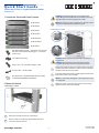
1. Unpack the Switch and Check Contents
ECS4120-28T
ECS4120-28P
ECS4120-28F
ECS4120-28F-I
ECS4120-28Fv2
ECS4120-28Fv2-I
ECS4120-52T
28T/28P/52T Mounting Kit — 4 brackets and 10 screws
28F/28F-I /28Fv2/28Fv2-I Mounting Kit — 2 brackets
and 4 screws
Four adhesive foot pads
Power cord — US, Continental Europe, or UK
Console cable — RJ-45 to DB-9
Documentation—Quick Start Guide (this document)
and Safety and Regulatory Information
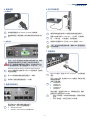
2. Mount the Switch
a. Mounting in a Rack
Attach the brackets to the front of the switch.
Use the screws and cage nuts supplied with the rack to
secure the switch in the rack.
2
1
1
2
Caution:
Installing the switch in a rack requires two
people. One person should position the switch in the rack,
while the other secures it using the rack screws.
Note:
The switch can also be installed on a desktop or shelf
using the included adhesive rubber foot pads.
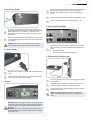
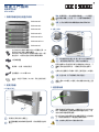
b. Mounting on a Wall
Caution:
Wall mount the switch with the network ports
facing down.
Caution:
Wall mount the switch using four brackets
(included) attached to the front and rear of the switch.
Rotate the brackets 90 degrees and attach them to the front
and rear of the switch. Use three screws for the front brackets
and two screws for the rear brackets.
In the required location, mark and drill eight holes in the wall
for the wall anchors (not included).
Note:
For a wood wall, drilling holes and using wall anchors
is not required.
Mount the switch on the wall and secure it in place using
eight #12 wood screws (not included).
3
3
1
1
2
2
1
2
3
28-Port and 52-Port L2 Gigabit Ethernet Switches
ECS4120 Series
www.edge-core.com
E122017-CS-R03
150200001742H

– 2 –
3. Ground the Switch
Ensure the rack on which the switch is to be mounted is
properly grounded and in compliance with ETSI ETS 300 253.
Verify that there is a good electrical connection to the
grounding point on the rack (no paint or isolating surface
treatment).
Attach an 18 AWG minimum grounding wire (not included)
to the grounding point on the switch rear panel, and then to
rack ground.
Caution:
The earth connection must not be removed
unless all supply connections have been disconnected.
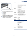
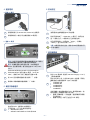
4. Connect Power
a. AC Power
Plug the power cord into a 100-240 VAC, 50-60 Hz AC power
source.
Insert the other end of the power cord directly into the AC
input socket on the back of the switch.
b. DC Power
Warning:
Before wiring the DC plug or connecting power
to the switch, ensure that power to the feed lines are turned
off at the supply circuit breaker or disconnected from the
power bus.
Warning:
This unit is intended to be supplied by a IEC/UL
listed DC power source suitable for whose input is rated DC
-48 to -60V, 3.0 A.
1
2
1
2
2
1
1
2
3 2
1
The ECS4120-28F/ECS4120-28F-I /ECS4120-28Fv2/ECS4120-
28Fv2-I switch supports the option of connecting an
external -48 to -60 VDC power source to its DC terminal
block.
Connect the -48 VDC power feed wire to the DC plug “-” pin.
Connect the ground/return wire to the DC plug “+” pin.
5. Verify Switch Operation
Verify basic switch operation by checking the system LEDs.
When operating normally, the following LEDs should be on
green:
◆
28T/28P/52T: DIAG
◆
28F/28F-I/28Fv2/28Fv2-I: PWR and DIAG
6. Perform Initial Configuration
Connect a PC to the switch console port using the included
console cable.
Configure the PC’s serial port: 115200 bps, 8 characters, no
parity, one stop bit, 8 data bits, and no flow control.
Log in to the CLI using default settings: Username “admin”
and password “admin.”
Note:
For further information on switch configuration,
refer to the Web Management Guide and CLI Reference
Guide.
1
2
3
1
1
3
1
2
1
2
3
Quick Start Guide

– 3 –
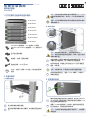
7. Connect Network Cables
For RJ-45 ports, connect 100-ohm Category 5, 5e or better
twisted-pair cable.
For the SFP/SFP+ slots, first install SFP/SFP+ transceivers and
then connect fiber optic cabling to the transceiver ports.
The following transceivers are supported:
◆
10GBASE-CR
◆
10GBASE-SR
◆
1000BASE-SX
◆
1000BASE-LX
◆
1000BASE-T
As connections are made, check the port status LEDs to be
sure the links are valid. Press the Mode button to change
from Ethernet to PoE status:
◆
On/Blinking Green — Port has a valid link. Blinking
indicates network activity.
◆
On Amber — Port is supplying PoE power.
2
1
3
1
2
3
Hardware Specifications
Switch Chassis
Size (W x D x H)
28T: 44.0 x 22.0 x 4.4 cm (17.32 x 8.66 x 1.73 in)
28P: 44.0 x 33.0 x 4.4 cm (17.32 x 12.99 x 1.73 in)
28F/28F-I /28Fv2/28Fv2-I : 44.0 x 22.0 x 4.4 cm
(17.32 x 8.66 x 1.73 in)
52T: 44.0 x 28.0 x 4.4 cm (17.32 x 11.02 x 1.73 in)
Weight
28T: 2.47 kg (5.45 lb)
28P: 4.53 kg (10.0 lb)
28F/28F-I /28Fv2/28Fv2-I : 2.82 kg (6.22 lb)
52T: 3.76 kg (8.29 lb)
Temperature
Operating: 0° C to 50° C (32° F to 122° F)
Operating: -10° C to 65° C (14° F to 149° F,
ECS4120-28F-I and ECS4120-28Fv2-I only)
Storage: -40° C to 70° C (-40° F to 158° F)
Humidity Operating: 5% to 95% (non-condensing)
AC Input Power
28T: 100-240 VAC, 50/60 Hz, 0.37-0.22 A
28P: 100-240 VAC, 50/60 Hz, 4.6-2.1 A
28F/28F-I /28Fv2 : 100-240 VAC, 50/60 Hz 1 A
28Fv2-I : 100-240 VAC, 50/60 Hz 1.2 A
52T: 100-240 VAC, 50/60 Hz, 0.75-0.42 A
DC Input Power 28F: -48 – -60 VDC, 3.0 A
Max. Power
Consumption
28T: 20 W
28P: 460 W
28F/28F-I /28Fv2/28Fv2-I : 60 W
52T: 60 W
PoE Power
Budget
28P: 370 W
Regulatory Compliances
Emissions
EN 55022:2010, Class A
EN 55032:2012+AC:2013, Class A
EN 61000-3-2:2014, Class A
EN 61000-3-3:2013
FCC Class A
VCCI Class A
CE Mark
CCC GB 9254-2008 Class A
Immunity
EN 55024:2010
IEC 61000-4-2/3/4/5/6/8/11
Safety
UL (CSA 22.2 No 60950-1 & UL60950-1)
CB (IEC 60950-1/EN 60950-1)
CCC GB 4943.1-2011
Taiwan RoHS CNS 15663
Quick Start Guide

– 4 –
超高速交换器
ECS4120 系列
1. 打开交换机的包装并检查内装物
ECS4120-28T
ECS4120-28P
ECS4120-28F
ECS4120-28F-I
ECS4120-28Fv2
ECS4120-28Fv2-I
ECS4120-52T
28T/28P/52T 安装套件 — 4 个支架和 10 个螺钉
28F/28F-I /28Fv2/28Fv2-I 安装套件 — 2 个支架和 4 个
螺钉
四个粘合型支脚垫
电源线 — 美规、欧规或英规
控制台线缆 — RJ-45 至 DB-9
文档 — 快速入门指南 (本文档)以及安全和管制
信息
将支架安装到交换机前面。
使用机架随附的螺丝和卡式螺母,将交换机固定到支架
上。
2
1
1
2
小心:
将交换机安装在墙上,并使网络端口朝下。
小心:
使用交换机前面和后面配备 (附带)的四个支架
将其安装在墙上。
将支架旋转 90 度后将其安装到交换机前面和后面。将三
个螺钉用于前面支架,将一个螺钉用于后面支架。
在所需的位置,在墙壁上标记和钻出 8 个孔用于墙壁固
定锚 (未附带)。
注意:
如果是木墙,不需要钻孔和使用墙壁固定锚。
将交换机安装到墙上,使用 8 个 #12 木螺钉 (未附带)
将其固定到位。
确保要安装交换机的机架已正确接地,并且符合 ETSI ETS
300 253 规范。确认到机架上接地点的电力连接良好 (未
经过油漆或绝缘表面处理)。
将最小 18 AWG 的接地线 (未附带)连接到交换机后面
板上的接地点,再连接到机架接地端。
小心:
必须在所有电源连接都断开的情况下,才能移除
接地连接。
3
3
1
1
2
2
1
2
3
1
2
1
2

– 5 –
将电源线插接到 100-240 VAC, 50-60 Hz 交流电源。
将电源线的另一端直接插入到交换机背后的交流输入插
口。
警告:
在插入直流线插头或连接交换机电源之前,确保
断路器的供电线电源已关闭或已从电源总线中断开。
警告:
根据制造商提供的产品规格,本机将由适用 IEC/
UL 直流电源供电,输入额定值为 DC -48 到 -60V, 3.0A。
ECS4120-28F/ECS4120-28F-I /ECS4120-28Fv2/ECS4120-
28Fv2-I 交换机可支持外部 -48 到 -60 V 直流电源,连接到
其直流接线盒。
将 -48 V 直流供电线连接到直流插头 “-” 针脚。
将接地 / 回线连接到直流插头 “+” 针脚。
通过系统 LED 检查交换机的基本运行。
正常工作时,以下 LED 应亮起绿色 :
◆
28T/28P/52T: DIAG
◆
28F/28F-I /28Fv2/28Fv2-I: PWR 和 DIAG
2
1
1
2
3 2
1
1
2
3
1
1
使用附带的控制台线将 PC 连接到交换机控制台端口。
配置 PC 的串行端口 : 115200 bps, 8 个字符,无奇偶校
验,一个停止位, 8 个数据位,无流程控制。
使用默认设置登录 CLI: 用户名 “admin” 和密码 “admin”。
注意:
有关交换机配置的详情,请参考 Web 管理指南和
CLI 参考指南。
对于 RJ-45 端口,连接 100-ohm Category 5、5e 或双绞线
更好。
对于 SFP/SFP+ 槽,先安装 SFP/SFP+ 收发器,再将光纤连
接到收发器端口。
支持下列收发器:
◆
10GBASE-CR
◆
10GBASE-SR
◆
1000BASE-SX
◆
1000BASE-LX
◆
1000BASE-T
建立连接后,检查端口状态 LED,确保连接正常。按模
式按钮从以太网更改为 PoE 状态 :
◆
开机 / 闪烁绿色 — 端口具有有效连接。闪烁表示网络
活动。
◆
开机 / 琥珀色 — 端口正在进行 PoE 供电。
3
1
2
1
2
3
2
1
3
1
2
3

– 6 –
交换机机箱
尺寸
(W x D x H)
28T: 44.0 x 22.0 x 4.4 cm (17.32 x 8.66 x 1.73 英寸 )
28P: 44.0 x 33.0 x 4.4 cm (17.32 x 12.99 x 1.73 英
寸 )
28F/28F-I /28Fv2/28Fv2-I: 44.0 x 22.0 x 4.4 cm
(17.32 x 8.66 x 1.73 英寸 )
52T: 44.0 x 28.0 x 4.4 cm (17.32 x 11.02 x 1.73 英
寸 )
重量
28T: 2.47 kg (5.45 磅 )
28P: 4.53 kg (10.0 磅 )
28F/28F-I /28Fv2/28Fv2-I: 2.82 kg (6.22 磅 )
52T: 3.76 kg (8.29 磅 )
温度
工作时: 0° C 到 50° C (32° F 到 122° F)
工作时:-10° C 到 65° C (14° F 到 149° F,仅限
ECS4120-28F-I 及 ECS4120-28Fv2-I)
存放时:-40° C 到 70° C (-40° F 到 158° F)
湿度
工作时: 5% 到 95% (无冷凝)
交流输入电源
28T: 100-240 V 交流, 50/60 Hz, 0.37-0.22 A
28P: 100-240 V 交流, 50/60 Hz, 4.6-2.1 A
28F/28F-I /28Fv2: 100-240 V 交流,50/60 Hz, 1 A
28Fv2-I: 100-240 V 交流, 50/60 Hz, 1.2 A
52T: 100-240 V 交流, 50/60 Hz, 0.75-0.42 A
直流输入电源
28F: -48 – -60 V 直流, 3.0 A
最大功耗
28T: 20 W
28P: 460 W
28F/28F-I /28Fv2/28Fv2-I: 60 W
52T: 60 W
PoE 功耗
28P: 370 W
管制符合性
辐射
EN 55022:2010, Class A
EN 55032:2012+AC:2013, Class A
EN 61000-3-2:2014, Class A
EN 61000-3-3:2013
FCC Class A
VCCI Class A
CE Mark
CCC GB 9254-2008 Class A
抗干扰性
EN 55024:2010
IEC 61000-4-2/3/4/5/6/8/11
安全
UL (CSA 22.2 No 60950-1 & UL60950-1)
CB (IEC 60950-1/EN 60950-1)
CCC GB 4943.1-2011
台湾 RoHS
CNS 15663

– 7 –
1.
ECS4120-28T
ECS4120-28P
ECS4120-28F
ECS4120-28F-I
ECS4120-28Fv2
ECS4120-28Fv2-I
ECS4120-52T
28T/28P/52T 4 10
28F/28F-I /28Fv2/28Fv2-I 2
4
4
—
— RJ-45 DB-9
—
2.
a.
2
1
1
2
:
b.
: RJ-45
:
90
( )
:
8 #12 ( )
3.
ETSI ETS 300
253
18 AWG
:
3
3
1
1
2
2
1
2
3
1
2
1
2

– 8 –
4.
a. AC
100-240 VAC, 50-60 Hz
AC
b. DC
IEC/UL DC -48 -60V
3.0 A
ECS4120-28F/ECS4120-28F-I /ECS4120-28Fv2/
ECS4120-28Fv2-I DC -48 -60
VDC DC DC
-48 V -
+
5.
LED
LED
◆
28T/28P/52T: DIAG
◆
28F/28F-I /28Fv2/28Fv2-I: PWR DIAG
2
1
1
2
3 2
1
1
2
3
1
1
6.
PC
115200 bps 8
1 8
admin
admin CLI
Web
CLI
7.
RJ-45 100-ohm Category 5 5e
SFP/SFP+ SFP/SFP+
:
◆
10GBASE-CR
◆
10GBASE-SR
◆
1000BASE-SX
◆
1000BASE-LX
◆
1000BASE-T
LED
PoE :
◆
/ —
◆
/ – PoE
3
1
2
1
2
3
2
1
3
1
2
3

– 9 –
(W x D x H)
28T: 44.0 x 22.0 x 4.4 cm
17.32 x 8.66 x 1.73
28P: 44.0 x 33.0 x 4.4 cm
17.32 x 12.99 x 1.73
28F/28F-I /28Fv2/28Fv2-I: 44.0 x 22.0 x 4.4 cm
17.32 x 8.66 x 1.73
52T: 44.0 x 28.0 x 4.4 cm
17.32 x 11.02 x 1.73
28T: 2.47 kg (5.45
28P: 4.53 kg (10.0
28F/28F-I /28Fv2/28Fv2-I: 2.82 kg (6.22
52T: 3.76 kg (8.29
0° C 50° C (32° F 122° F
-10° C 65° C (14° F 149° F
ECS4120-28F-I ECS4120-28Fv2-I
-40° C 70° C -40° F 158° F
28T: 100-240 V 50/60 Hz, 0.37-0.22 A
28P: 100-240 V 50/60 Hz, 4.6-2.1 A
28F/28F-I /28Fv2: 100-240 V 50/60 Hz, 1
A
28Fv2-I: 100-240 V 50/60 Hz, 1.2 A
52T: 100-240 V 50/60 Hz, 0.75-0.42 A
28F: -48 – -60 V 3.0 A
28T: 20 W
28P: 460 W
28F/28F-I /28Fv2/28Fv2-I: 60 W
52T: 60 W
PoE
28P: 370 W
EN 55022:2010, Class A
EN 55032:2012+AC:2013, Class A
EN 61000-3-2:2014, Class A
EN 61000-3-3:2013
FCC Class A
VCCI Class A
CE Mark
CCC GB 9254-2008 Class A
EN 55024:2010
IEC 61000-4-2/3/4/5/6/8/11
UL (CSA 22.2 No 60950-1 & UL60950-1)
CB (IEC 60950-1/EN 60950-1)
CCC GB 4943.1-2011
RoHS
CNS 15663
-
 1
1
-
 2
2
-
 3
3
-
 4
4
-
 5
5
-
 6
6
-
 7
7
-
 8
8
-
 9
9


他の言語で
- English: Edge-Core ECS4120-28F User manual