ASISTENCIA TÉCNICA
SUSTITUCIÓN DE LAS TECLAS Y DE LOS INTERRUPTORES
Para obtener asistencia técnica, envíe un correo electrónico
a support@epomaker.com con su número de pedido y una
descripción detallada de su problema.
Normalmente respondemos a las consultas en un plazo
de 24 horas. Si ha adquirido su teclado a través de un
distribuidor o no en ninguna tienda oficial de Epomaker,
póngase en contacto con ellos directamente para cualquier
ayuda adicional.
GARANTÍA
La garantía de EPOMAKER cubre cualquier defecto de fábrica
que pueda afectar al correcto funcionamiento de su compra.
No cubre ningún daño que pueda ocurrir por el desgaste
normal. Si su producto es defectuoso, le enviaremos una
unidad de reemplazo. Las unidades de reemplazo pueden
requerir que usted envíe la unidad defectuosa de vuelta a
Epomaker.
Ofrecemos una garantía de 1 año para nuestros productos
cuando se compran en nuestra página web (EPOMAKER.
com). Su artículo no estará cubierto por su garantía de 1 año
si la inspección muestra cualquier signo de modificación
o cambios no soportados por el producto original, estos
incluyen: Cambio de componentes internos, Montaje y
remontaje del producto, Sustitución de baterías, etc.
Sólo cubriremos el artículo si se ha comprado en nuestras
tiendas oficiales. Usted no tiene una garantía con nosotros si
usted compró el artículo de otro revendedor o de la misma
manera. Por favor, póngase en contacto con la tienda en la
que compró el producto para resolver los problemas.
FOROS DE LA COMUNIDAD
https://discord.gg/2q3Z7C2
Únase a nuestra comunidad y aprenda junto
a otros entusiastas de los teclados.
ES
https://www.reddit.com/user/epomaker/
Logo
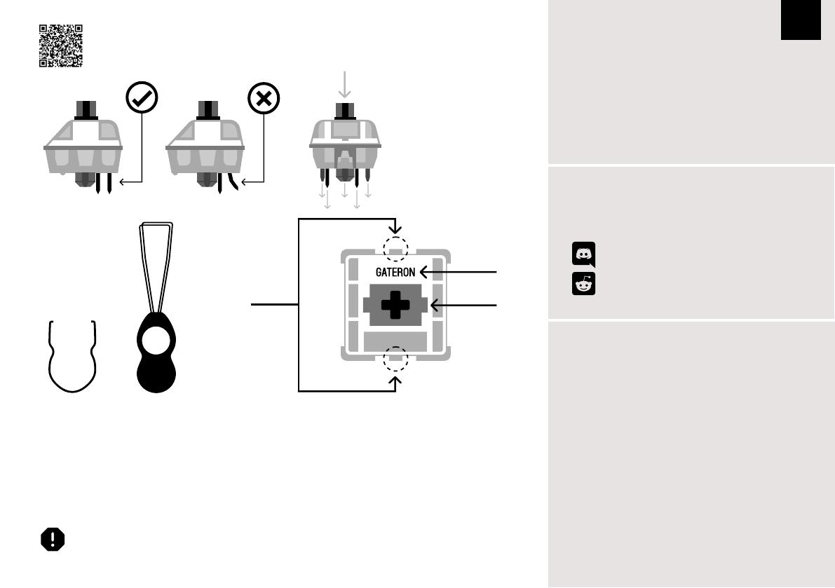
Eje del interruptor
La herramienta de extracción de interruptores se alinea
verticalmente con el interruptor para soltar el plástico que
asegura el interruptor a la placa.
Ejemplo de un
interruptor visto
desde arriba después
de quitar la tapa del
teclado para preparar
la extracción del
interruptor.
Interruptor
mecánico
Extractor de
interruptores
Extractor de
tapas de teclas
Para obtener una guía completa sobre cómo quitar las tapas de las teclas y los interruptores, escanee el código
QR o escriba en su navegador:
https://epomaker.com/blogs/guides/diy-guide-how-to-remove-and-replace-your-mechanical-keyboard-switches
Herramientas
incluidas
1. Agarre su herramienta de extracción de interruptores y alinee
los dientes de agarre verticalmente (en el eje Y) en el centro del
interruptor, como se muestra en el gráfico de ejemplo anterior.
2. Agarre el interruptor con el extractor de interruptores y aplique
presión hasta que el interruptor se libere de la placa
3. Con una fuerza firme pero suave, separe el interruptor del teclado
con un movimiento vertical.
Quitar los interruptores
1. Compruebe que todos los pasadores metálicos del interruptor están
perfectamente rectos y limpios.
2. Alinee el interruptor verticalmente para que el logotipo de Gateron
esté orientado hacia el norte. Los pines deben alinearse con el PBC
del teclado.
3. Presione el interruptor hacia abajo hasta que oiga un clic. Esto significa
que los clips del interruptor se han unido a la placa del teclado.
4. Inspeccione el interruptor para asegurarse de que está bien conectado
a su teclado, y pruébelo.
Instalar los interruptores
Nota: Si la tecla no funciona es posible que haya doblado uno de los interruptores al instalarlo. Saque el interruptor y repita el proceso
Las clavijas pueden dañarse de forma irreparable y necesitar ser reemplazadas si este proceso no se realiza correctamente. No aplique
nunca una fuerza excesiva al sustituir las tapas de las teclas o los interruptores. Si no puede retirar o instalar las tapas de las teclas o los
interruptores, póngase en contacto con el servicio de atención al cliente lo antes posible para evitar que el teclado sufra daños debido a errores
de funcionamiento.
Tenga cuidado. Asegúrese de
que las clavijas estén alinea-
das con las ranuras.
Antes de instalar los interruptores, asegúrese de que las clavijas
estén limpias y rectas.
Empuje hacia
abajo.
1. Descomprima el archivo para encontrar los archivos .exe y .json.
2. Instale el archivo .exe en su ordenador.
3. Ejecute el software VIA una vez instalado.
4. Importe el archivo JSON para poder editar la configuración del Mini Cat 64 dentro de VIA.
1. Descomprimir el archivo para encontrar los archivos .exe y .json.
2. Descomprimir el archivo .dmg
3. Arrastre el software VIA a su carpeta de aplicaciones para instalarlo.
4. Autorice el software VIA en: Preferencias del Sistema > Seguridad y Privacidad.
5. Importe el archivo JSON para poder editar la configuración del Mini Cat 64 dentro de VIA.


