
I
Quick Start
Quick Start
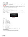
Thank you for purchasing the MSI
®
X299 XPOWER GAMING AC
motherboard. This Quick Start section provides demonstration
diagrams about how to install your computer. Some of the
installations also provide video demonstrations. Please link to the
URL to watch it with the web browser on your phone or tablet. You
may have even link to the URL by scanning the QR code.
MSI
®
X299 XPOWER GAMING AC
PC
URL
QR URL
MSI
®
X299 XPOWER GAMING AC .
.
URL . QR
URL .
MSI
®
X299 XPOWER GAMING AC
URL QR
code
MSI
®
X299 XPOWER GAMING AC
QRURL

II
Quick Start
Youtube
http://v.youku.com/v_show/
id_XMjgwNzMzNTM0NA==.html
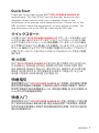
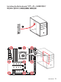
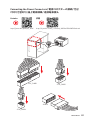
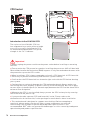
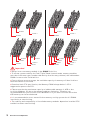
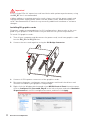
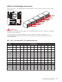
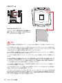
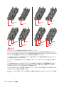
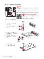
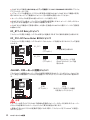
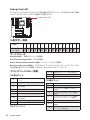
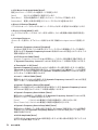
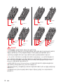
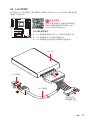
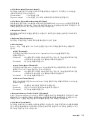
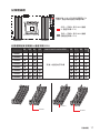
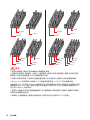
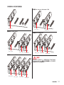
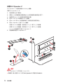
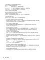
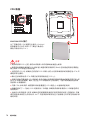
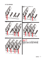
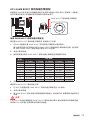
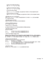
Installing a Processor/ CPU/
/ /
1
2
3
6
4
5
789
https://youtu.be/ecdkLMmkya4
10
11
12
13

III
Quick Start
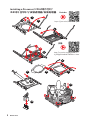
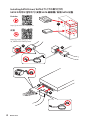
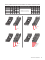
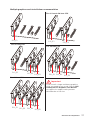
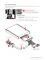
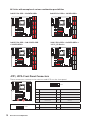
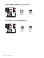
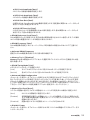
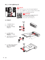
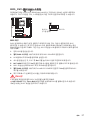
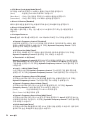
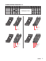
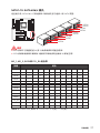
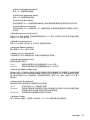
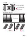
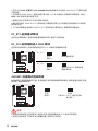
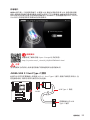
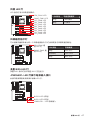
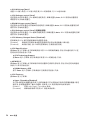
Installing DDR4 memory/ DDR4/
DDR4 / DDR4 / DDR4
http://youtu.be/T03aDrJPyQs
Youtube
http://v.youku.com/v_show/id_XNzUyMTI5ODI4.html
1
2
2
3
DIMMC1

IV
Quick Start
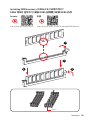
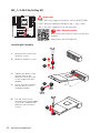
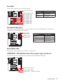
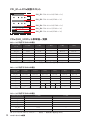
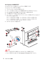
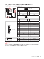
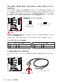
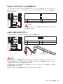
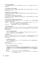
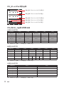
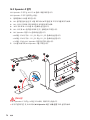
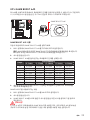
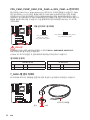
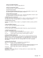
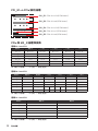
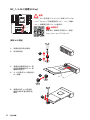
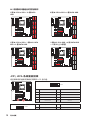
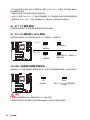
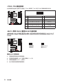
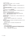
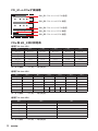
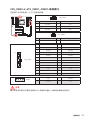
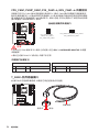
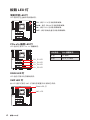
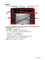
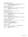
Connecting the Front Panel Header/
/ /
/
http://youtu.be/DPELIdVNZUI
1
2 10
9
JFP1
1 HDD LED + 2 Power LED +
3 HDD LED - 4 Power LED -
5 Reset Switch 6 Power Switch
7 Reset Switch 8 Power Switch
9 Reserved 10 No Pin
RESET SW
POWER SW
POWER LED+
POWER LED-
HDD LED
HDD LED
RESET SW
JFP1
HDD LED
HDD LED -
HDD LED +
POWER LED -
POWER LED +
POWER LED
Youtube
http://v.youku.com/v_show/id_XNjcyMTczMzM2.html

V
Quick Start
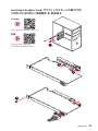
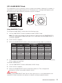
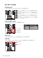
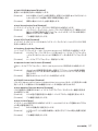
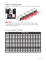
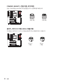
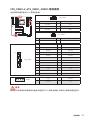
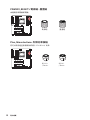
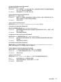
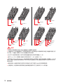
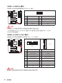
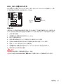
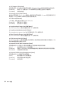
Installing the Motherboard/ /
/ /
1
2

VI
Quick Start
1
2
3
4
5
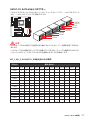
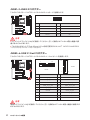
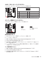
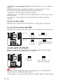
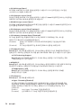
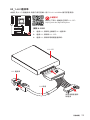
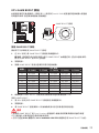
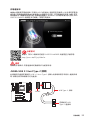
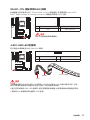
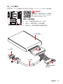
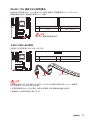
Installing SATA Drives/ SATA/
SATA / SATA / SATA
http://youtu.be/RZsMpqxythc
http://v.youku.com/v_show/
id_XNDkzODU5MTky.html
Youtube

VII
Quick Start
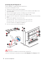
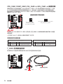
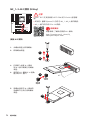
1
2
3
4
5
6
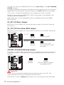
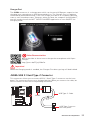
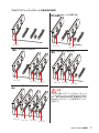
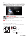
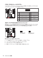
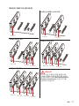
Installing a Graphics Card/ /
/ /
http://youtu.be/mG0GZpr9w_A
http://v.youku.com/v_show/
id_XNDkyOTc3MzQ4.html
Youtube

VIII
Quick Start
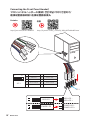
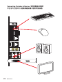
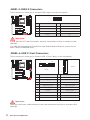
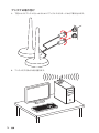
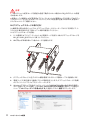
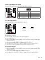
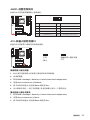
Connecting Peripheral Devices/ /
/ /

IX
Quick Start
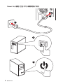
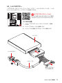
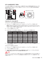
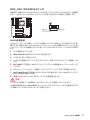
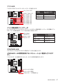
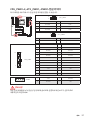
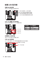
Connecting the Power Connectors/ /
/ /
http://youtu.be/gkDYyR_83I4 http://v.youku.com/v_show/id_XNDkzODU0MDQw.html
Youtube
ATX_PWR1
JPWR1
CPU_PWR1
CPU_PWR2

X
Quick Start
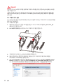
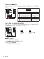
1
4
2
3
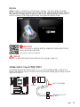
Power On/ / / /

1
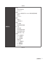
Contents
Contents
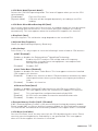
Safety Information ................................................................................................. 3
Specifications ......................................................................................................... 4
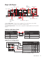
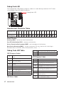
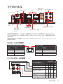
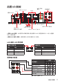
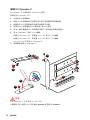
Rear I/O Panel ...................................................................................................... 11
LAN Port LED Status Table................................................................................... 11
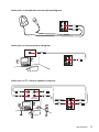
Audio Ports Configuration .................................................................................... 11
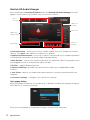
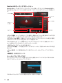
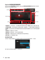
Realtek HD Audio Manager .................................................................................. 12
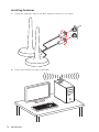
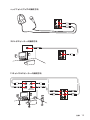
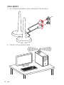
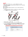
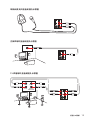
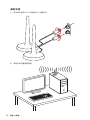
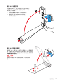
Installing Antennas ............................................................................................... 14
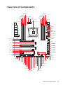
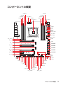
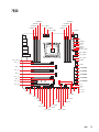
Overview of Components .................................................................................... 15
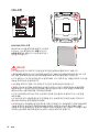
CPU Socket ........................................................................................................... 16
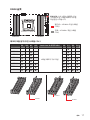
DIMM Slots ............................................................................................................ 17
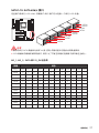
PCI_E1~6: PCIe Expansion Slots .......................................................................... 20
PCIe and M2_3 slots bandwidth table .................................................................. 20
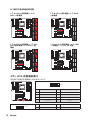
U2_1: U.2 Connector ............................................................................................. 23
M2_1~3: M.2 Slots (Key M) ................................................................................... 24
Installing the M.2 Xpander-Z ............................................................................... 26
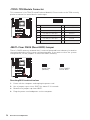
SATA1~10: SATA 6Gb/s Connectors ..................................................................... 27
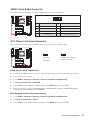
JFP1, JFP2: Front Panel Connectors ................................................................... 28
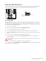
OC1: GAME BOOST Knob ..................................................................................... 29
OC_RT1: OC Retry Jumper ................................................................................... 30
OC_FS1: OC Force Enter BIOS Jumper ................................................................ 30
JSLOW1: Slow Mode Booting Jumper .................................................................. 30
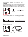
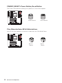
CPU_PWR1~2, ATX_PWR1, JPWR1: Power Connectors ...................................... 31
JUSB1~2: USB 2.0 Connectors ............................................................................. 32
JUSB3~4: USB 3.1 Gen1 Connectors ................................................................... 32
JUSB5: USB 3.1 Gen2 Type-C Connector ............................................................. 33
CPU_FAN1, PUMP_FAN1, SYS_FAN1~4, EXS_FAN1~4: Fan Connectors ............ 34
T_SEN1: Thermal Sensor Connector ................................................................... 34
JAUD1: Front Audio Connector ............................................................................ 35
JCI1: Chassis Intrusion Connector ....................................................................... 35
JTPM1: TPM Module Connector ........................................................................... 36
JBAT1: Clear CMOS (Reset BIOS) Jumper ........................................................... 36
BIOS_SW1: Multi-BIOS Switch ............................................................................. 37
POWER1, RESET1: Power Button, Reset Button ................................................. 38
Plus, Minus buttons: BCLK-Ratio buttons ........................................................... 38
VRAID1: Virtual RAID on CPU Connector ............................................................. 39
JLED1: RGB LED connector ................................................................................. 39
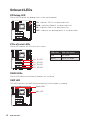
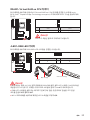
Onboard LEDs ...................................................................................................... 40
EZ Debug LED ....................................................................................................... 40

2
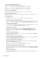
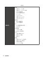
Contents
PCIe x16 slot LEDs................................................................................................ 40
DIMM LEDs ........................................................................................................... 40
XMP LED ............................................................................................................... 40
Fan LEDs ............................................................................................................... 41
Fan Speed Indicators ............................................................................................ 41
Multi-BIOS LEDs ................................................................................................... 41
JPWRLED1: LED light demonstration power input connector ............................ 41
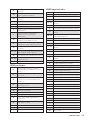
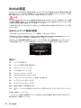
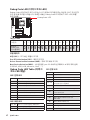
Debug Code LED ................................................................................................... 42
Hexadecimal Character Table .............................................................................. 42
Boot Phases .......................................................................................................... 42
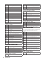
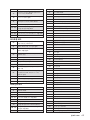
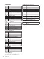
Debug Code LED Table ......................................................................................... 42
ACPI States Codes ................................................................................................ 44
CPU Temperature ................................................................................................. 44
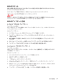
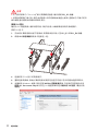
Updating LED Firmware ....................................................................................... 45
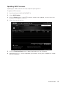
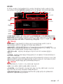
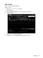
BIOS Setup ........................................................................................................... 46
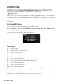
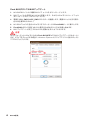
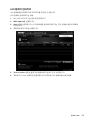
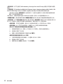
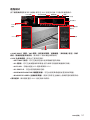
Entering BIOS Setup ............................................................................................. 46
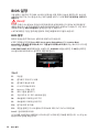
Resetting BIOS ...................................................................................................... 47
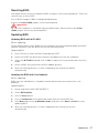
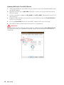
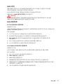
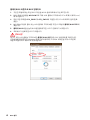
Updating BIOS ....................................................................................................... 47
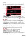
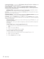
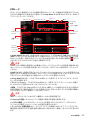
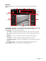
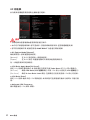
EZ Mode ................................................................................................................ 49
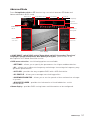
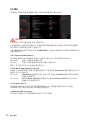
Advanced Mode .................................................................................................... 51
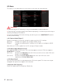
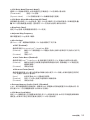
OC Menu................................................................................................................ 52
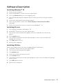
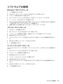
Software Description ........................................................................................... 59
Installing Windows
®
10 ......................................................................................... 59
Installing Drivers .................................................................................................. 59
Installing Utilities ................................................................................................. 59

3
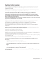
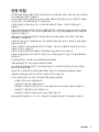
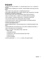
Safety Information
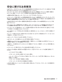
Safety Information
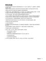
y The components included in this package are prone to damage from electrostatic
discharge (ESD). Please adhere to the following instructions to ensure successful
computer assembly.
y Ensure that all components are securely connected. Loose connections may cause
the computer to not recognize a component or fail to start.
y Hold the motherboard by the edges to avoid touching sensitive components.
y It is recommended to wear an electrostatic discharge (ESD) wrist strap when
handling the motherboard to prevent electrostatic damage. If an ESD wrist strap is
not available, discharge yourself of static electricity by touching another metal object
before handling the motherboard.
y Store the motherboard in an electrostatic shielding container or on an anti-static pad
whenever the motherboard is not installed.
y Before turning on the computer, ensure that there are no loose screws or metal
components on the motherboard or anywhere within the computer case.
y Do not boot the computer before installation is completed. This could cause
permanent damage to the components as well as injury to the user.
y If you need help during any installation step, please consult a certified computer
technician.
y Always turn off the power supply and unplug the power cord from the power outlet
before installing or removing any computer component.
y Keep this user guide for future reference.
y Keep this motherboard away from humidity.
y Make sure that your electrical outlet provides the same voltage as is indicated on the
PSU, before connecting the PSU to the electrical outlet.
y Place the power cord such a way that people can not step on it. Do not place anything
over the power cord.
y All cautions and warnings on the motherboard should be noted.
y If any of the following situations arises, get the motherboard checked by service
personnel:
Liquid has penetrated into the computer.
The motherboard has been exposed to moisture.
The motherboard does not work well or you can not get it work according to user
guide.
The motherboard has been dropped and damaged.
The motherboard has obvious sign of breakage.
y Do not leave this motherboard in an environment above 60C (140F), it may damage
the motherboard.

4
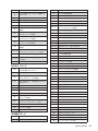
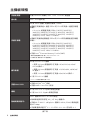
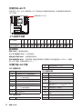
Specifications
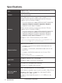
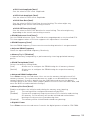
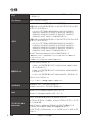
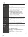
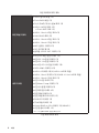
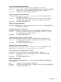
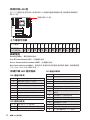
Specifications
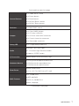
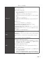
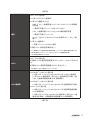
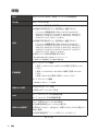
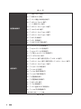
CPU
Supports Intel
®
Core™ X-Series Processor Family for
LGA2066 Socket
Chipset Intel
®
X299 Chipset
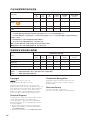
Memory
y 8x DDR4 memory slots, support up to 128GB*
y Quad channel memory architecture with the CPU that
supports up to 4-channels DDR4**
X-series processor support DDR4 4133(OC)/ 4000(OC)/
3866(OC)/ 3800(OC)/ 3733(OC)/ 3600(OC)/ 3466(OC)/
3400(OC)/ 3333(OC)/ 3200(OC)/ 3000(OC)/ 2933(OC)/
2800(OC)/ 2667/ 2400/ 2133 MHz*
y Dual channel memory architecture with the CPU that
supports up to 2-channels DDR4**
X-series processor support DDR4 4500(OC)/ 4400(OC)/
4333(OC)/ 4266(OC)/ 4200(OC)/ 4133(OC)/ 4000(OC)/
3866(OC)/ 3800(OC)/ 3733(OC)/ 3600(OC)/ 3466(OC)/
3400(OC)/ 3333(OC)/ 3200(OC)/ 3000(OC)/ 2933(OC)/
2800(OC)/ 2667/ 2400/ 2133 MHz*
y Supports Intel
®
Extreme Memory Profile (XMP)
* For the latest information about memory, please visit http://www.msi.com
** Please refer the DIMM Slots section for more details.
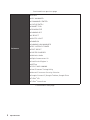
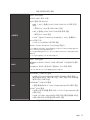
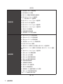
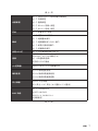
Expansion Slots
y 4x PCIe 3.0 x16 slots
Support x16/x0/x16/x8, x8/x8/x16/x8 mode with the
44-lane CPU.*
Support x16/x0/x8/x4, x8/x8/x8/x4 mode with the 28-
lane CPU.*
Support x8/x0/x4/x4 mode with the 16-lane CPU.*
y 1x PCIe 3.0 x1 slot
* Please refer to page 20 for PCIe 3.0 bandwidth table.
Multi-GPU
y Supports NVIDIA
®
SLI
™
Technology
y Supports AMD
®
CrossFire
™
Technology
LAN
y 1x Intel I219-V Gigabit LAN controller
y 1x Intel I211 Gigabit LAN controller
Wirsless LAN &
Bluetooth
®
Intel
®
Dual Band Wireless-AC 8265 module
y The Wireless module is pre-install in the M2_3 (Key-E) slot.
y Supports Wi-Fi 802.11 a/b/g/n/ac, dual band (2.4GHz,
5GHz) up to 867 Mbps speed.
y Supports Dual Mode Bluetooth
®
2.1, 2.1+EDR, 3.0, 4.0,
BLE, 4.2
Continued on next page

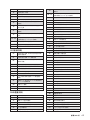
5
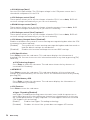
Specifications
Continued from previous page
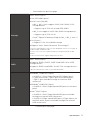
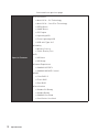
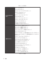
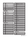
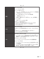
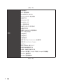
Storage
Intel
®
X299 Chipset
y 10x SATA 6Gb/s ports*
y 3x M.2 slots (Key M)*
M2_1, M2_2 slots support 2242/ 2260 /2280/ 22110
storage devices
Supports up to PCIe 3.0 x4 and SATA 6Gb/s
M2_3 slot supports 2242/ 2260 /2280 storage devices
Supports up to PCIe 3.0 x4
Intel
®
Optane™ Memory Ready for M2_1, M2_2 slots **
y 1x U.2 port *
Supports PCIe 3.0 x4 NVMe storage
y Supports Intel
®
Smart Response Technology***
* M.2 slots and SATA ports share the same bandwidth. Please refer to page 27
for M.2 & SATA combination table.
** Please refer to the Intel
®
Optane™ Memory Configuration Guide on MSI
website.
***The functions will be supported depend on the CPU.
RAID
Intel
®
X299 Chipset
y Supports RAID 0, RAID1, RAID 5 and RAID 10 for SATA
storage devices
y Supports RAID 0 and RAID1 for M.2 PCIe storage devices*
* M.2 PCIe RAID volume can be created with M.2 GENIE.
USB
y ASMedia
®
ASM3142 Chipset
3x USB 3.1 Gen2 (SuperSpeed USB 10Gbps) ports
(1 Type-A port and 1 Type-C port on the back panel,
1 Type-C port available through the internal USB
connector)
y ASMedia
®
ASM1074 Chipset
6x USB 3.1 Gen1 (SuperSpeed USB) ports on the back
panel
y Intel
®
X299 Chipset
4x USB 3.1 Gen1 (SuperSpeed USB) ports available
through the internal USB connectors
6x USB 2.0 (High-speed USB) ports (2 Type-A ports on
the back panel, 4 ports available through the internal
USB connectors)
Continued on next page

6
Specifications
Continued from previous page
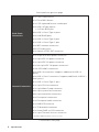
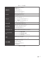
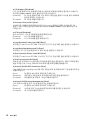
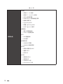
Back Panel
Connectors
y 1x Clear CMOS button
y 1x Flash BIOS Button
y 1x PS/2 keyboard/ mouse combo port
y 2x USB 2.0 Type-A ports
1x Flash BIOS port
y 6x USB 3.1 Gen1 Type-A ports
y 2x LAN (RJ45) ports
y 1x USB 3.1 Gen2 Type-A port
y 1x USB 3.1 Gen2 Type-C port
y 2x WiFi antenna connectors
y 5x OFC audio jacks
y 1x Optical S/PDIF OUT connector
Internal Connectors
y 1x 24-pin ATX main power connector
y 1x 8-pin ATX 12V power connector
y 1x 4-pin ATX 12V power connector
y 1x flat 4-pin ATX 12V power connector*
y 10x SATA 6Gb/s connectors
y 2x USB 2.0 connectors (supports additional 4 USB 2.0
ports)
y 2x USB 3.1 Gen1 connectors (supports additional 4 USB 3.1
Gen1 ports)
y 1x USB 3.1 Gen2 Type-C port
y 1x 4-pin CPU fan connector
y 1x 4-pin Water Pump connector
y 4x 4-pin system fan connectors
y 4x 4-pin extend fan connectors
y 2x Front panel connectors
y 1x Front panel audio connector
y 1x RGB LED connector
y 1x TPM module connector
y 1x Virtual RAID on CPU connector
y 1x 2-pin Thermal Sensors connector
* Provides additional power to PCIe x16 slots
Continued on next page

7
Specifications
Continued from previous page
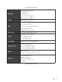
Internal Buttons
y 1x GAME BOOST knob
y 1x Power button
y 1x Reset button
y 1x BCLK+/ Ratio+ button
y 1x BCLK-/ Ratio- button
Switches y 1x Multi-BIOS switch
Jumper
y 1x Clear CMOS jumper
y 1x OC retry connector
y 1x OC force enter BIOS connector
y 1x Chassis Intrusion connector
y 1x Slow mode connector
Debug LED y 1x 2-Digit Debug Code LED
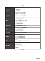
Audio
y Realtek
®
ALC1220 Codec
y 7.1-Channel High Definition Audio
y Supports S/PDIF output
I/O Controller NUVOTON NCT6795 Controller Chip
Hardware Monitor
y CPU/System temperature detection
y CPU/System fan speed detection
y CPU/System fan speed control
Form Factor
y EATX Form Factor
y 12 in. x 10.7 in. (30.5 cm x 27.2 cm)
BIOS Features
y 2x 128 Mb flash
y UEFI AMI BIOS
y ACPI 6.0, SM BIOS 3.0
y Multi-language
Continued on next page

8
Specifications
Continued from previous page
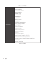
Software
y Drivers
y APP MANAGER
y COMMAND CENTER
y LIVE UPDATE 6
y SMART TOOL
y DRAGON EYE
y GAMING APP
y X-BOOST
y MYSTIC LIGHT
y RAMDISK
y GAMING LAN MANAGER
y DPC LATENCY TUNER
y FAST BOOST
y SUPER CHARGER
y Nahimic Audio
y XSplit Gamecaster V2
y SteelSeriesEngine 3
y WTFast
y CPU-Z MSI GAMING
y Intel Extreme Tuning Utility
y Norton™ Internet Security Solution
y Google Chrome™ ,Google Toolbar, Google Drive
y TriDef
®
VR
y TriDef
®
SmartCam
Continued on next page

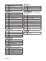
9
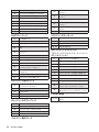
Specifications
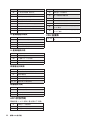
Continued from previous page
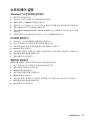
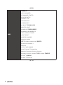
Special Features
y Audio
Audio Boost 4
Nahimic 2
y Network
GAMING LAN with Gaming LAN Manager
Dual LAN
Intel WiFi
y Storage
Turbo U.2
Triple Turbo M.2
y Fan
Pump Fan
Smart Fan Control
y LED
Mystic Light
Mystic Light Extension
Mystic light SYNC
EZ DEBUG LED
y Protection
DDR4 Steel Armor
M.2 Shield FROZR
M.2 Shield
Steel Backplate
PCI-E Steel Armor
U.2 Steel Armor
M.2 Steel Armor
VR Cover
Continued on next page

10
Specifications
Continued from previous page
Special Features
y Performance
Multi GPU – SLI Technology
Multi GPU – CrossFire Technology
DDR4 Boost
GAME Boost
OC Engine
Lightning USB
Front Lightning USB
USB with Type A+C
y Stability
Military Class 6
7000+ Quality Test
y VR
VR Boost
VR Ready
y Gamer Experience
GAMING HOTKEY
GAMING MOUSE Control
y BIOS
Click BIOS 5
Flash BIOS
Dual BIOS
y Certification
Quadro SLI Ready
Quadro Ready
GAMING Certified
SteelSeries Certified
ページが読み込まれています...
ページが読み込まれています...
ページが読み込まれています...
ページが読み込まれています...
ページが読み込まれています...
ページが読み込まれています...
ページが読み込まれています...
ページが読み込まれています...
ページが読み込まれています...
ページが読み込まれています...
ページが読み込まれています...
ページが読み込まれています...
ページが読み込まれています...
ページが読み込まれています...
ページが読み込まれています...
ページが読み込まれています...
ページが読み込まれています...
ページが読み込まれています...
ページが読み込まれています...
ページが読み込まれています...
ページが読み込まれています...
ページが読み込まれています...
ページが読み込まれています...
ページが読み込まれています...
ページが読み込まれています...
ページが読み込まれています...
ページが読み込まれています...
ページが読み込まれています...
ページが読み込まれています...
ページが読み込まれています...
ページが読み込まれています...
ページが読み込まれています...
ページが読み込まれています...
ページが読み込まれています...
ページが読み込まれています...
ページが読み込まれています...
ページが読み込まれています...
ページが読み込まれています...
ページが読み込まれています...
ページが読み込まれています...
ページが読み込まれています...
ページが読み込まれています...
ページが読み込まれています...
ページが読み込まれています...
ページが読み込まれています...
ページが読み込まれています...
ページが読み込まれています...
ページが読み込まれています...
ページが読み込まれています...
ページが読み込まれています...
ページが読み込まれています...
ページが読み込まれています...
ページが読み込まれています...
ページが読み込まれています...
ページが読み込まれています...
ページが読み込まれています...
ページが読み込まれています...
ページが読み込まれています...
ページが読み込まれています...
ページが読み込まれています...
ページが読み込まれています...
ページが読み込まれています...
ページが読み込まれています...
ページが読み込まれています...
ページが読み込まれています...
ページが読み込まれています...
ページが読み込まれています...
ページが読み込まれています...
ページが読み込まれています...
ページが読み込まれています...
ページが読み込まれています...
ページが読み込まれています...
ページが読み込まれています...
ページが読み込まれています...
ページが読み込まれています...
ページが読み込まれています...
ページが読み込まれています...
ページが読み込まれています...
ページが読み込まれています...
ページが読み込まれています...
ページが読み込まれています...
ページが読み込まれています...
ページが読み込まれています...
ページが読み込まれています...
ページが読み込まれています...
ページが読み込まれています...
ページが読み込まれています...
ページが読み込まれています...
ページが読み込まれています...
ページが読み込まれています...
ページが読み込まれています...
ページが読み込まれています...
ページが読み込まれています...
ページが読み込まれています...
ページが読み込まれています...
ページが読み込まれています...
ページが読み込まれています...
ページが読み込まれています...
ページが読み込まれています...
ページが読み込まれています...
ページが読み込まれています...
ページが読み込まれています...
ページが読み込まれています...
ページが読み込まれています...
ページが読み込まれています...
ページが読み込まれています...
ページが読み込まれています...
ページが読み込まれています...
ページが読み込まれています...
ページが読み込まれています...
ページが読み込まれています...
ページが読み込まれています...
ページが読み込まれています...
ページが読み込まれています...
ページが読み込まれています...
ページが読み込まれています...
ページが読み込まれています...
ページが読み込まれています...
ページが読み込まれています...
ページが読み込まれています...
ページが読み込まれています...
ページが読み込まれています...
ページが読み込まれています...
ページが読み込まれています...
ページが読み込まれています...
ページが読み込まれています...
ページが読み込まれています...
ページが読み込まれています...
ページが読み込まれています...
ページが読み込まれています...
ページが読み込まれています...
ページが読み込まれています...
ページが読み込まれています...
ページが読み込まれています...
ページが読み込まれています...
ページが読み込まれています...
ページが読み込まれています...
ページが読み込まれています...
ページが読み込まれています...
ページが読み込まれています...
ページが読み込まれています...
ページが読み込まれています...
ページが読み込まれています...
ページが読み込まれています...
ページが読み込まれています...
ページが読み込まれています...
ページが読み込まれています...
ページが読み込まれています...
ページが読み込まれています...
ページが読み込まれています...
ページが読み込まれています...
ページが読み込まれています...
ページが読み込まれています...
ページが読み込まれています...
ページが読み込まれています...
ページが読み込まれています...
ページが読み込まれています...
ページが読み込まれています...
ページが読み込まれています...
ページが読み込まれています...
ページが読み込まれています...
ページが読み込まれています...
ページが読み込まれています...
ページが読み込まれています...
ページが読み込まれています...
ページが読み込まれています...
ページが読み込まれています...
ページが読み込まれています...
ページが読み込まれています...
ページが読み込まれています...
ページが読み込まれています...
ページが読み込まれています...
ページが読み込まれています...
ページが読み込まれています...
ページが読み込まれています...
ページが読み込まれています...
ページが読み込まれています...
ページが読み込まれています...
ページが読み込まれています...
ページが読み込まれています...
ページが読み込まれています...
ページが読み込まれています...
ページが読み込まれています...
ページが読み込まれています...
ページが読み込まれています...
ページが読み込まれています...
ページが読み込まれています...
ページが読み込まれています...
ページが読み込まれています...
ページが読み込まれています...
ページが読み込まれています...
ページが読み込まれています...
ページが読み込まれています...
ページが読み込まれています...
ページが読み込まれています...
ページが読み込まれています...
ページが読み込まれています...
ページが読み込まれています...
ページが読み込まれています...
ページが読み込まれています...
ページが読み込まれています...
ページが読み込まれています...
ページが読み込まれています...
ページが読み込まれています...
ページが読み込まれています...
ページが読み込まれています...
ページが読み込まれています...
ページが読み込まれています...
ページが読み込まれています...
ページが読み込まれています...
ページが読み込まれています...
ページが読み込まれています...
ページが読み込まれています...
ページが読み込まれています...
ページが読み込まれています...
ページが読み込まれています...
ページが読み込まれています...
ページが読み込まれています...
ページが読み込まれています...
ページが読み込まれています...
ページが読み込まれています...
ページが読み込まれています...
ページが読み込まれています...
ページが読み込まれています...
ページが読み込まれています...
ページが読み込まれています...
ページが読み込まれています...
ページが読み込まれています...
ページが読み込まれています...
ページが読み込まれています...
ページが読み込まれています...
ページが読み込まれています...
ページが読み込まれています...
ページが読み込まれています...
ページが読み込まれています...
ページが読み込まれています...
ページが読み込まれています...
ページが読み込まれています...
ページが読み込まれています...
ページが読み込まれています...
ページが読み込まれています...
ページが読み込まれています...
ページが読み込まれています...
ページが読み込まれています...
ページが読み込まれています...
ページが読み込まれています...
ページが読み込まれています...
ページが読み込まれています...
ページが読み込まれています...
ページが読み込まれています...
ページが読み込まれています...
ページが読み込まれています...
ページが読み込まれています...
ページが読み込まれています...
ページが読み込まれています...
ページが読み込まれています...
ページが読み込まれています...
ページが読み込まれています...
ページが読み込まれています...
ページが読み込まれています...
ページが読み込まれています...
ページが読み込まれています...
ページが読み込まれています...
ページが読み込まれています...
ページが読み込まれています...
ページが読み込まれています...
ページが読み込まれています...
ページが読み込まれています...
ページが読み込まれています...
ページが読み込まれています...
ページが読み込まれています...
ページが読み込まれています...
ページが読み込まれています...
ページが読み込まれています...
ページが読み込まれています...
ページが読み込まれています...
ページが読み込まれています...
ページが読み込まれています...
ページが読み込まれています...
ページが読み込まれています...
ページが読み込まれています...
ページが読み込まれています...
ページが読み込まれています...
ページが読み込まれています...
ページが読み込まれています...
ページが読み込まれています...
ページが読み込まれています...
ページが読み込まれています...
ページが読み込まれています...
ページが読み込まれています...
ページが読み込まれています...
ページが読み込まれています...
ページが読み込まれています...
ページが読み込まれています...
-
 1
1
-
 2
2
-
 3
3
-
 4
4
-
 5
5
-
 6
6
-
 7
7
-
 8
8
-
 9
9
-
 10
10
-
 11
11
-
 12
12
-
 13
13
-
 14
14
-
 15
15
-
 16
16
-
 17
17
-
 18
18
-
 19
19
-
 20
20
-
 21
21
-
 22
22
-
 23
23
-
 24
24
-
 25
25
-
 26
26
-
 27
27
-
 28
28
-
 29
29
-
 30
30
-
 31
31
-
 32
32
-
 33
33
-
 34
34
-
 35
35
-
 36
36
-
 37
37
-
 38
38
-
 39
39
-
 40
40
-
 41
41
-
 42
42
-
 43
43
-
 44
44
-
 45
45
-
 46
46
-
 47
47
-
 48
48
-
 49
49
-
 50
50
-
 51
51
-
 52
52
-
 53
53
-
 54
54
-
 55
55
-
 56
56
-
 57
57
-
 58
58
-
 59
59
-
 60
60
-
 61
61
-
 62
62
-
 63
63
-
 64
64
-
 65
65
-
 66
66
-
 67
67
-
 68
68
-
 69
69
-
 70
70
-
 71
71
-
 72
72
-
 73
73
-
 74
74
-
 75
75
-
 76
76
-
 77
77
-
 78
78
-
 79
79
-
 80
80
-
 81
81
-
 82
82
-
 83
83
-
 84
84
-
 85
85
-
 86
86
-
 87
87
-
 88
88
-
 89
89
-
 90
90
-
 91
91
-
 92
92
-
 93
93
-
 94
94
-
 95
95
-
 96
96
-
 97
97
-
 98
98
-
 99
99
-
 100
100
-
 101
101
-
 102
102
-
 103
103
-
 104
104
-
 105
105
-
 106
106
-
 107
107
-
 108
108
-
 109
109
-
 110
110
-
 111
111
-
 112
112
-
 113
113
-
 114
114
-
 115
115
-
 116
116
-
 117
117
-
 118
118
-
 119
119
-
 120
120
-
 121
121
-
 122
122
-
 123
123
-
 124
124
-
 125
125
-
 126
126
-
 127
127
-
 128
128
-
 129
129
-
 130
130
-
 131
131
-
 132
132
-
 133
133
-
 134
134
-
 135
135
-
 136
136
-
 137
137
-
 138
138
-
 139
139
-
 140
140
-
 141
141
-
 142
142
-
 143
143
-
 144
144
-
 145
145
-
 146
146
-
 147
147
-
 148
148
-
 149
149
-
 150
150
-
 151
151
-
 152
152
-
 153
153
-
 154
154
-
 155
155
-
 156
156
-
 157
157
-
 158
158
-
 159
159
-
 160
160
-
 161
161
-
 162
162
-
 163
163
-
 164
164
-
 165
165
-
 166
166
-
 167
167
-
 168
168
-
 169
169
-
 170
170
-
 171
171
-
 172
172
-
 173
173
-
 174
174
-
 175
175
-
 176
176
-
 177
177
-
 178
178
-
 179
179
-
 180
180
-
 181
181
-
 182
182
-
 183
183
-
 184
184
-
 185
185
-
 186
186
-
 187
187
-
 188
188
-
 189
189
-
 190
190
-
 191
191
-
 192
192
-
 193
193
-
 194
194
-
 195
195
-
 196
196
-
 197
197
-
 198
198
-
 199
199
-
 200
200
-
 201
201
-
 202
202
-
 203
203
-
 204
204
-
 205
205
-
 206
206
-
 207
207
-
 208
208
-
 209
209
-
 210
210
-
 211
211
-
 212
212
-
 213
213
-
 214
214
-
 215
215
-
 216
216
-
 217
217
-
 218
218
-
 219
219
-
 220
220
-
 221
221
-
 222
222
-
 223
223
-
 224
224
-
 225
225
-
 226
226
-
 227
227
-
 228
228
-
 229
229
-
 230
230
-
 231
231
-
 232
232
-
 233
233
-
 234
234
-
 235
235
-
 236
236
-
 237
237
-
 238
238
-
 239
239
-
 240
240
-
 241
241
-
 242
242
-
 243
243
-
 244
244
-
 245
245
-
 246
246
-
 247
247
-
 248
248
-
 249
249
-
 250
250
-
 251
251
-
 252
252
-
 253
253
-
 254
254
-
 255
255
-
 256
256
-
 257
257
-
 258
258
-
 259
259
-
 260
260
-
 261
261
-
 262
262
-
 263
263
-
 264
264
-
 265
265
-
 266
266
-
 267
267
-
 268
268
-
 269
269
-
 270
270
-
 271
271
-
 272
272
-
 273
273
-
 274
274
-
 275
275
-
 276
276
-
 277
277
-
 278
278
-
 279
279
-
 280
280
-
 281
281
-
 282
282
-
 283
283
-
 284
284
-
 285
285
-
 286
286
-
 287
287
-
 288
288
-
 289
289
-
 290
290
-
 291
291
-
 292
292
-
 293
293
-
 294
294
-
 295
295
-
 296
296
-
 297
297
-
 298
298
-
 299
299
-
 300
300
-
 301
301
-
 302
302
-
 303
303
-
 304
304
-
 305
305
-
 306
306
-
 307
307
-
 308
308
-
 309
309
-
 310
310
-
 311
311
-
 312
312
-
 313
313
-
 314
314


