
AIMC-3202 Startup Manual 1
Before you begin installing your card, please make sure
that the following items have been shipped:
1. AIMC-3202 Bare System x 1
P/N: AIMC-3202-00A1E
(AIMC-3202-01A1E)
2. Driver CD x 1 P/N: 2061302900
3. USB 2.0 Cable x 1 P/N: 1700014398
4. USB 3.0 Cable x 1 P/N: 1700020277-01
5. Four-port USB Cable x 1 P/N: 1700014398
6. LPT Cable x 1 P/N: 1700002223
7. Mounting Brackets x 2 P/N: 1960014487T00C
8. Rubber Foot x 4 P/N: 1990012452S000
If any of these items are missing or damaged, please con-
tact your distributor or sales representative immediately.
Note 1: For detailed contents of AIMC-3202, please refer
to information on the enclosed CD-ROM (in PDF
format).
Note 2: Acrobat Reader is required to view any PDF file.
Acrobat Reader can be downloaded at: get.
adobe.com/reader (Acrobat is a trademark of
Adobe)
AIMC-3202
Micro Computer, Intel
®
Core™ i7/i5/i3 CPU,
H110, 2 Expansions, 250W 80Plus PSU
Startup Manual
Processor System
Processor
System
(0 ~ 40° C for
65W CPU)
(0 ~ 45° C for
35W CPU)
CPU
i7-
6700
i7-
6700TE
i5-
6500
i5-
6500TE
i3-
6100
i3-
6100TE
G
4400
G
4400TE
G
3900
G
3900TE
Core 4 4 4 4 2 2 2 2 2 2
Base
Frequency
3.4
GHz
2.4
GHz
3.2
GHz
2.3
GHz
3.7
GHz
2.7
GHz
3.3
GHz
2.9
GHz
2.8
GHz
2.6 GHz
L3 Cache 8M 8M 6M 6M 4M 4M 3M 3M 2M 2M
Chipset H110
BIOS AMI 128Mb SPI Flash
* Part Number iX-XXXXTX & GXXXXXX can use 1U CPU
Cooler for 2 Expansion slots. Other CPUs have to use 1.5U
Cooler for 1 Expansion slot.
BIOS
• AMI 128 Mbit SPI Flash
Chipset
• Intel H110
Memory
• Supports Dual Channel DDR4 1866/2133 16 GB per
DIMM, Max capacity is 32 GB
Graphic
• Chipset: Intel
®
HD Graphics
Expansion Slot
• AIMC-3202-00:
- One PCIe x16 (Upper-layer slot)
- One PCIe x4 (Lower-layer slot)
• AIMC-3202-01:
- One PCI (Upper-layer slot)
- One PCIe x16 (Lower-layer slot)
Ethernet
• Chipset support:
- LAN 1: Intel
®
I219V
- LAN 2: Intel
®
I211AT
• Connection: 2 x on-board RJ-45 connector with LED
indicators
SATA
• Max Data Transfer Rate: 600 MB/s (SATA 3.0)
• HDD Bay: 2 internal 2.5”
I/O Interface
• Display: VGA + DVI-D
• USB: 3 USB3.0
• PS/2: 1
Watchdog Timer
• Programmable 1~255 sec/min
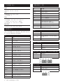
Specications
Packing List
For more information on this and other Advantech
products, please visit our website at:
http://www.advantech.com
http://www.advantech.com/eplatform
For technical support and service, please visit our
support website at:
http://support.advantech.com.tw/support/default.
aspx
This manual is for the AIMC-3202 Series Rev. A1.
Part No. 2001320200
Printed in China
1st Edition
October 2016

2 AIMC-3202 Startup Manual
Power Supply
• Output Rating: AC 250W, ATX
• Input Voltage: 100 VAC ~ 240 VAC
Cooling
• System Fan: 2 (6cm / 27.7 CFM)
• Air Filter: Yes
Environment
• Operating Temperature: 0 ~ 40°C (32 ~ 104°F)
• Non-operating Temperature: -20 ~ 60°C (-4 ~ 140°F)
• Operating Humidity: 10 ~ 85% @ 40°C, non-condensing
• Non-operating Humidity: 10 ~ 95% @ 40°C, non-
condensing
Physical Characteristics
• Dimension (WxHxD): 232 x 90 x 232 mm
The board has a number of jumpers that allow you to con-
figure your system to suit your application. The table below
lists the function of each of the jumpers and connectors.
Connectors
Label Function
LPT1 Parallel port, supports SPP/EPP/ECP mode
LAN1 Intel I219V
LAN2 Intel I211AT
VGA1 VGA connector
KBMS1 External keyboard/mouse connector
COM12 Box header for RS-232*2
FP1
HDD LED, power LED, SNMP SM_Bus,
reset, power on/off
JCASE1 Case open
CPUFAN1 CPU FAN connector (4-pin)
LANLED1 LAN1/2 LED connector
HDAUD1 HD audio extension module connector
USB1 USB port 1 (USB 3.0 port)
USB23 USB port 2, 3 (USB 3.0 port)
USB45 USB port 4, 5 (USB 2.0)
USB67 USB port 6, 7 (USB 2.0)
USB89 USB port 8, 9 (USB 2.0)
USB11 Type A connector on board (USB 2.0)
SATA0 Serial ATA1 (SATA 3.0)
SATA1 Serial ATA2 (SATA 3.0)
SATA2 Serial ATA3 (SATA 3.0)
SATA3 Serial ATA4 (SATA 3.0)
CPU1 CPU Socket
DIMMA1 Memory connector channel A
DIMMB1 Memory connector channel B
GPIO1 GPIO pin header
LPC1 Low pin count module expansion pin-header
PWR1 12 V, 5 V power connector
DVI1
DVI connector
DP1
Display pin header to stack board (Display
type depends on optional stack board)
EXPCIE1 mini PCIe pin header to stack board
MINIPCIE
MSATA
M-SATA (default) or mini-PCIe connector
(optional for PCE-4129)
Jumpers
Label Function
JCMOS1 CMOS clear
JOBS1+JWDT1
Hardware monitor alarm+watchdog
timer output selection
JME1 Enable ME
JCMOS1: Clear CMOS
Closed Pins Result
1-2 Keep CMOS (Default)
2-3 Clear CMOS
JOBS1+JWDT1: Hardware monitor alarm+watchdog
timer output selection
Function Jumper Setting
2-3 Enable watchdog timer (Default)
4-5 Enable Hardware monitor alarm (Default)
JME1: Enable ME
Closed Pins Result
1-2
Enable ME
(Default)
2-3 Disable ME
Jumpers and Connectors
Jumpers and Connectors
(Cont.)
Specications (Cont.)

AIMC-3202 Startup Manual 3
The drivers for the AIMC-3202 are located on the software
installation CD. Please click through the folder and follow
the on screen instructions to install them.
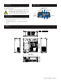
Caution! The computer is supplied with a battery-pow-
ered realtime clock circuit. There is a danger
of explosion if battery is incorrectly replaced.
Replace only with same or equivalent type
recommended by the manufacturer. Discard
used batteries according to manufacturer’s
instructions.
This device complies with the requirements in Part 15 of
the FCC rules. Operation is subject to the following two
conditions:
1. This device may not cause harmful interference;
2. This device must accept any interference received,
including interference that may cause undesired
operation.
Declaration of Conformity
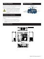
System I/O Interface
PCI-E x16 or PCI
(AIMC-3202-01)
Alarm LED
PCI-E x4 or PCI x16
(AIMC-3202-01)
2 x RS-232
HDD LED
2 USB 3.0
USB 3.0VGADVI
250Watt 80Plus
Power Supply
Dual LANPS/2
Software Installation
System Dimensions

AIMC-3202快速入门手册
5
安装系统之前,用户需确认包装中含有本设备以及下面所
列各项:
1. AIMC-3202准系统 x 1 P/N: AIMC-3202-00A1E
(AIMC-3202-01A1E)
2. 驱动光盘 x 1 P/N: 2061302900
3. USB2.0电缆 x 1 P/N: 1700014398
4. USB3.0电缆 x 1 P/N: 1700020277-01
5. 4端口USB电缆 x 1 P/N: 1700014398
6. LPT电缆 x 1 P/N: 1700002223
7. 安装支架 x 2 P/N: 1960014487T00C
8. 橡胶垫脚 x 4 P/N: 1990012452S000
如果其中任何一项缺失或损坏,请立即与经销商或销售代
表联系。
注1: 有关AIMC-3202产品的详细信息,请参考CD光盘中
的信息(PDF格式)。
注2: 阅读PDF文件需要使用Acrobat Reader。用户可从
以下路径下载Acrobat Reader:get.adobe.com/
reader(Acrobat为Adobe公司的商标)
AIMC-3201
微型计算机,
Intel® Core™ i7/i5/i3 CPU,
110,2
扩展槽,
250W 80Plus PSU
快速入门手册
处理器系统
处理器系统
(65W CPU的温
度范围为
0 ~ 40°C,
35W CPU的温
度范围为
0 ~ 45°C)
CPU
i7-
6700
i7-
6700TE
i5-
6500
i5-
6500TE
i3-
6100
i3-
6100TE
G
4400
G
4400TE
G
3900
G
3900TE
内核数量 4 4 4 4 2 2 2 2 2 2
基频
3.4
GHz
2.4
GHz
3.2
GHz
2.3
GHz
3.7
GHz
2.7
GHz
3.3
GHz
2.9
GHz
2.8
GHz
2.6 GHz
三级缓存 8M 8M 6M 6M 4M 4M 3M 3M 2M 2M
芯片组 H110
BIOS AMI 128Mb SPI Flash
* 料号iX-XXXXTX & GXXXXXX的2个扩展槽可使用1U CPU冷却
器,而其它CPU需要为1个扩展槽使用1.5U冷却器。
BIOS
• AMI 128 Mbit SPI Flash
芯片组
• Intel 110
内存
• 支持双通道DDR4 1866/2133, 每个DIMM为16 GB,最大容
量为32 GB
显示
• 芯片组: Intel
®
HD Graphics
扩展插槽
• AIMC-3202-00:
- 1个PCIe x16(上层插槽)
- 1个PCIe x4(下层插槽)
• AIMC-3202-01:
- 1个PCI(上层插槽)
- 1个PCIe x16(下层插槽)
以太网
• 芯片组支持:
- LAN 1: Intel
®
I219V
- LAN 2: Intel
®
I211AT
• 连接:2个板载RJ-45接口,带LED指示灯
SATA
• 最大数据传输速率:600 MB/s (SATA 3.0)
• HDD磁盘盒:2个内置2.5”
I/O接口
• 显示:VGA + DVI-D
• USB:3个USB3.0接口
• PS/2:1
看门狗定时器
• 可编程1~255秒/分
产品规格
包装清单
如需了解有关本产品及研华其它产品的详细信息,请访
问我们的网站:
http://www.advantech.com
http://www.advantech.com/eplatform
如需技术服务与支持,请访问我们的技术支持网站:
http://support.advantech.com.tw/support/default.
aspx
本手册适用于AIMC-3202系列Rev. A1。
料号:2001320200
中国印刷
第一版
2016年10月

6 AIMC-3202快速入门手册
电源
• 输出功率:AC 250 W, ATX
• 输入电压: 100 VAC ~ 240 VAC
冷却
• 系统风扇: 2(6 cm/27.7 CFM)
• 空气过滤器:有
环境
• 工作温度: 0 ~ 40°C(32 ~ 104°F)
• 非工作温度: -20 ~ 60°C(-4 ~ 140°F)
• 工作湿度: 10 ~ 85% @ 40°C,非凝结
• 非工作湿度: 10 ~ 95% @ 40°C,非凝结
物理特性
• 尺寸(W x H x D): 232 x 90 x 232 mm
主板上有很多跳线允许用户配置系统,满足各种不同应用需
求。下表为每个跳线和接口的功能列表。
接口
接口 功能
LPT1 并行端口,支持SPP/EPP/ECP模式
LAN1 Intel I217V
LAN2 Intel I211AT
VGA1 VGA接口
KBMS1 外部键盘/鼠标接口
COM12 简牛,用于RS-232 * 2
FP1
HDD LED、电源LED、SNMP SM_Bus、
重启按钮、电源开关
JCASE1 机箱打开
CPUFAN1 CPU风扇接口(4针)
LANLED1 LAN1/2 LED指示灯接口
HDAUD1 HD音频扩展模块接口
USB1 USB接口1(USB3.0接口)
USB23 USB接口2、3(USB3.0接口)
USB45 USB接口4、5(USB2.0)
USB67 USB接口6、7(USB2.0)
USB89 USB接口8、9(USB2.0)
USB911 Type A板载接口(USB2.0)
SATA0 串行ATA1(SATA3.0)
SATA1 串行ATA2(SATA3.0)
SATA2 串行ATA3(SATA2.0)
SATA3 串行ATA4(SATA2.0)
CPU1 CPU插槽
DIMMA1 内存接口通道A1
DIMMB1 内存接口通道B1
GPIO1 GPIO排针
LPC1 低脚位模块扩展排针
PWR1 12 V、5 V电源接口
DVI1
DVI接口
DP1
连接到堆叠板的显示排针
(显示类型取决于选配堆叠板)
EXPCIE1 连接到堆叠板的mini PCIe排针
MINIPCIE MSATA
M-SATA(默认)或mini-PCIe接口
(选配适用于PCE-4129)
跳线
跳线 功能
JCMOS1 清除CMOS
JOBS1+JWDT1
硬件监视器报警 + 看门狗定时器输
出选择
JME1 启用ME
JCMOS1: 清除CMOS
闭合针脚 结果
1-2 保留CMOS(默认)
2-3 清除CMOS
JOBS1+JWDT1: 硬件监视器报警 + 看门狗定时器输出选择
闭合针脚 跳线设置
2-3 启用看门狗定时器(默认)
4-5 启用硬件监视器报警(默认)
JME1: 启用ME
闭合针脚 结果
1-2 启用ME(默认)
2-3 禁用ME
跳线和接口
跳线和接口(续)
产品规格(续)

AIMC-3202快速入门手册 7
AIMC-3202的驱动位于软件安装光盘中。请点击文件夹后并
按照屏幕指示进行操作。
注意! 计算机配置了由电池供电的实时时钟电路,如果
电池更换不正确,将有爆炸的危险。因此,只可
以使用制造商推荐的同一种或者同等型号的电池
进行替换。请按照制造商的指示处理旧电池。
本品符合FCC规则第15款限制。操作符合下列两种情况:
1. 此设备不可产生干扰,且
2. 此设备必须接受任何干扰,包括可能导致非预期造作
的干扰。
PCI-E x16 或 PCI
(AIMC-3202-01)
报警LED
PCI-E x4 或 PCI x16
(AIMC-3202-01)
2 x RS-232
HDD LED
2 USB 3.0
USB 3.0VGADVI
250Watt
80Plus电源
双LANPS/2
软件安装
符合性声明
系统I/O接口
系统尺寸
-
 1
1
-
 2
2
-
 3
3
-
 4
4
-
 5
5
-
 6
6


