Simplicity DEALER, STAMPED STEEL, FRAME HUNG ユーザーマニュアル

タイプ
ユーザーマニュアル

このマニュアルも適しています

Not for
Reproduction
1
Copyright © Briggs & Stratton Power Products Group, LLC
Milwaukee, WI USA All rights reserved.
80012602JA Rev. A
en
Dealer Mower Deck Manual
Stamped Steel - Frame Hung
ja
ー向電動芝刈機
タンィー - フレ ング
Not for
Reproduction
2
Not for
Reproduction
3
42˝
42˝
46˝
52˝
en
Illustrated procedures start on Page 4.
Corresponding text procedures start on Page 10.
ja
で示された手順は4ページ目開始
対応す説明は13ページ目開始。
Not for
Reproduction
4
1
1
2
3
4
5
Not for
Reproduction
5
4
1
3
5
6
7
8
9
42˝
2
2
10
12
11
4
1
3
5
6
7
8
46˝
52˝
9
10
11
12
46˝
52˝
2
2
Not for
Reproduction
6
B
A
< 1/8˝
(< 3 mm)
4
5
A
B
9/16
42˝ 52˝46˝
3B
12-14 psi
0,82-0,96 bar
10 psi
0,68 bar
1
2
3
3A
Not for
Reproduction
7
D
D
C
D
< 1/8˝
(< 3 mm)
8
9
D
C
3/4
10 10
10 10
9
9 9
7
46˝ 52˝
3C
C
D
D
D
D
C
3/4
< 1/8˝
(< 3 mm)
9 9
8
9 9
7
42˝
3C
Not for
Reproduction
8
8
42˝
42˝
46˝ 52˝
3
5
6
52˝
1
2
3
2
4
4
46˝
7
4
1
4
A
2
5
3
4
A
30 lb-ft
40.8 Nm
1/2
9/16
2
3
4
5
42˝
46˝ 52˝
5
Not for
Reproduction
9
46˝ 52˝
42˝
OIL
6
OIL
OIL
22-28˚
2
1
55 lb-ft
75 Nm
5/8
A
B
4
5
7
Not for
Reproduction
10
Safety
If you need assistance with the unit, please contact the
web site or phone number shown in the Customer Con-
tact Guide (if provided) or the Operator’s Manual.
WARNING
Failure to read and follow the safety warnings and
instructions in this document and in the operator’s
manual could result in death, serious injury, and/or
property damage.
The warnings and instructions must be read,
understood, and followed when setting-up, operating,
servicing, transporting, or storing the unit.
Safety Alert Symbol and Signal Words
The safety alert symbol is used to identify safety
information about hazards that can result in personal
injury. A signal word (DANGER, WARNING, or
CAUTION) is used with the alert symbol to indicate the
likelihood and potential severity of injury. In addition,
a hazard symbol may be used to represent the type of
hazard.
DANGER indicates a hazard which, if not avoided,
will result in death or serious injury.
WARNING indicates a hazard which, if not
avoided, could result in death or serious injury.
CAUTION indicates a hazard which, if not
avoided, could result in minor or moderate injury.
NOTICE: indicates an action that could result in damage to the
product.
CAUTION Stored Energy Hazard
Keep hands away from tension springs when
removing or installing mower deck or transmission
belts.
WARNING Amputation or Laceration Hazard
• DO NOT make adjustments or repairs while the
engine is running or the blades are rotating.
• DO NOT place hands or feet near rotating parts or
under the mower deck.
• Keep clear of the discharge opening at all times.
• Mower blades are sharp – wear heavy gloves when
handling them.
• On multi-bladed mowers, rotating one blade could
cause the other(s) to also rotate.
WARNING Thrown Objects Hazard
• DO NOT operate the mower deck or the tractor
unless the discharge deector or the complete
grass catcher assembly (if equipped) is properly
installed.
• Frequently check the condition of the discharge
deector and grass catcher assembly (if equipped)
for damage or wear and repair/replace with
manufacturer’s recommended parts as necessary.
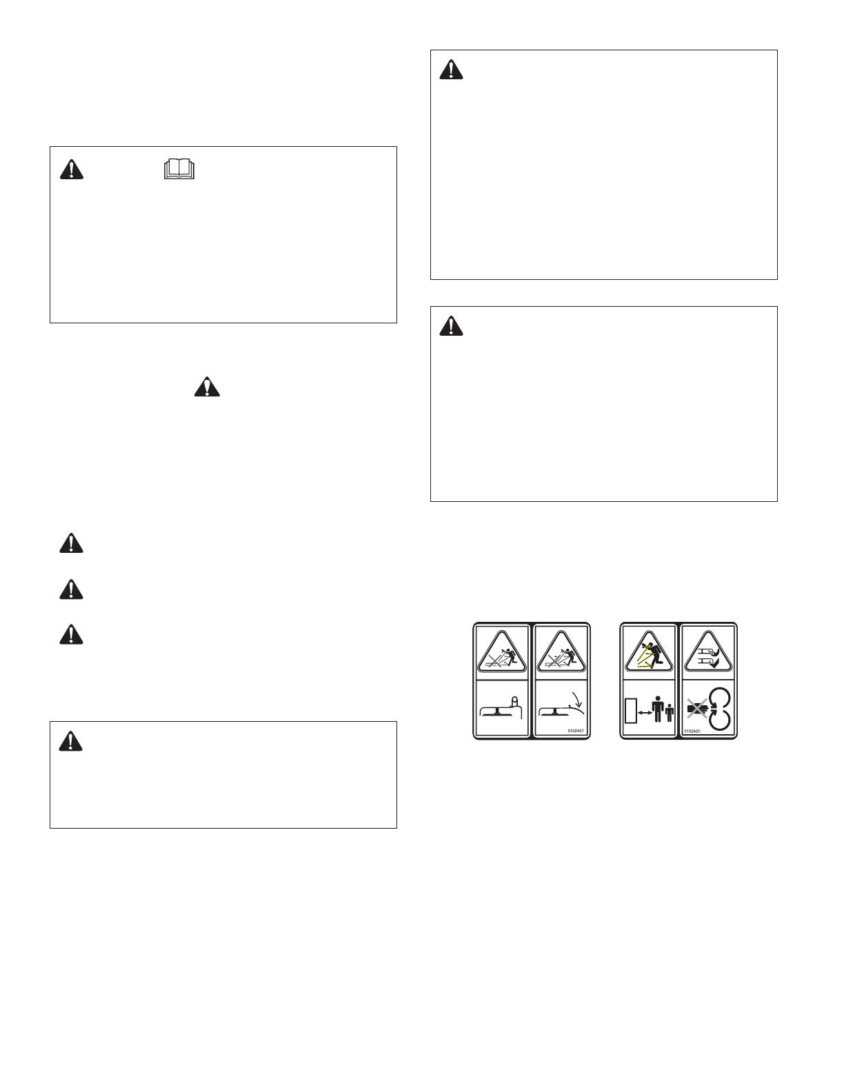
Deck Safety Decal
If any safety or instructional decals become worn or
damaged, and cannot be read, order replacement decals
from your dealer.
Safety Interlock System Tests
The tractor is equipped with a Safety Interlock System.
This
system is present for your safety: do not attempt to
bypass or tamper with the switches and devices. Check
the system using the Safety Interlock System Tests listed
in the Operator’s Manual.
Anytime the deck is removed and reinstalled, you must
perform this test.
Not for
Reproduction
11
en
Preparation for Procedures
1
Park tractor on a hard level surface.
WARNING
Before beginning any service work on the tractor or
mower deck:
set the parking brake,
turn off the PTO,
stop the engine then remove ignition key or safety key, and
disconnect the spark plug wire(s).
Deck Installation
2
1
Lower mower deck to the LOWEST height of cut.
2
Remove the hitch from the deck.
3
Turn the wheels fully to the left.
4
Slide mower deck under right side of tractor.
5
Turn wheels straight ahead.
6
Install hitch on deck.
7
Lift hitch lining up holes with hanger.
8
Insert rod and secure with retainer pin.
9
Connect the deck brackets to the tractor lift brackets.
10
Place belt on the PTO pulley.
11
Move idler arm to remove belt tension.
12
Place belt on remaining pulley as shown.
Deck Leveling
3A
WARNING
Wear heavy gloves when handling or
working around cutting blades. Blades are
extremely sharp and can cause severe
injury.
1
Place the mower deck to the MID-HEIGHT of cut
position.
2
Turn the wheels straight ahead.
3
Set the tires to the pressures shown.
SIDE-TO-SIDE
3B
4
Arrange the outside mower blades so they are
pointing side-to-side.
5
Measure the distance between the outside tips and
the ground.
The difference between measurement (A and B) (should
be less than 1/8″ (3 mm).
6
IF AN ADJUSTMENT IS NEEDED.
Tighten nuts (right or left side) as needed to adjust side-
to-side leveling.
FRONT-TO-BACK (42″)
3C
7
Arrange the left side mower blade so it points front-to-
back.
8
Measure the distance between the outside tips as
shown and the ground.
The difference between measurement (C and D) (should
be less than 1/8″ (3 mm).
9
IF AN ADJUSTMENT TO MEASUREMENT(D) IS
NEEDED.
To Lower (D) - Turn locknuts counterclockwise evenly
on both sides to keep deck level (Side-to-Side).
To Raise (D) - Turn locknuts clockwise evenly on both
sides to keep deck level (Side-to-Side).
FRONT-TO-BACK (46″ & 52″)
3C
7
Arrange the left side and center mower blades so they
point front-to-back.
8
Measure the distance between the outside tips as
shown and the ground.
The difference between measurement (C and D)
(should be less than 1/8″ (3 mm).
IF AN ADJUSTMENT TO MEASUREMENT(D) IS
NEEDED.
Note: Locknuts (9 and 10) must be turned evenly on both
sides to keep deck level (Side-to-Side).
Not for
Reproduction
12
Lubrication
6
Add grease to ttings where shown.
The pulleys are equipped with sealed bearings, which
does not require lubrication.
Blade Servicing
7
WARNING
Wear heavy gloves when handling or working around
cutting blades. Blades are extremely sharp and can
cause severe injury.
For your personal safety, if blade is damaged, it must
be replaced.
Note: Deck must be removed to service blades. See Deck
Removal
.
1
To remove blade, use a block of wood to prevent blade
rotation while loosening capscrew.
2
If the blade is in good condition, sharpen to an angle
of 22 to 28 degrees. DO NOT sharpen beyond existing
cutting edge.
3
After sharpening the blades, check to make sure they
are balanced. Place the center hole of the blade on a
nail lubricated with a drop of oil. A balanced blade will
remain level. If necessary, correct blade balance by
grinding the heavy end of the blade.
4
Reinstall the blade with the airlifts pointing up toward
the mower deck as shown.
WARNING
For your personal safety, the blade mounting
capscrews must be installed with a spring washer (A).
5
Ensure capscrews are tightened to the torque value
shown.
To LOWER - measurement (D):
9
Loosen nuts.
10
Tighten nuts counterclockwise.
11
Check measurement (Step 7 & 8).
When measurement is correct tighten nuts securely.
To RAISE - measurement (D):
9
Turn nuts clockwise.
10
Tighten nuts.
11
Check measurement (Step 7 & 8).
When measurement is correct tighten nuts securely.
Deck Removal
4
1
Lower mower deck to the LOWEST height of cut.
2
Move idler arm to remove belt tension.
3
Remove belt from pulley.
4
Remove belt from the PTO pulley.
5
Disconnect deck brackets from the tractor lift brackets.
6
Remove retainer pin and rod.
7
Remove hitch from deck.
8
Turn the wheels fully to the left.
9
Remove deck from right side of tractor.
Belt Replacement
5
REMOVE
1
Lower mower deck to the LOWEST height of cut.
2
Remove belt cover.
3
Move idler arm to remove belt tension.
4
Remove belt from pulley.
5
Remove belt from the PTO pulley.
6
Slide belt o - between pulley and belt guides (A).
Loosen bolt if necessary.
INSTALL
Note:
After installing new belt, check the belt guide (A)
gap it should be approximately 1/8˝ (3.3 mm) away from
belt. Torque the bolt as shown.
Not for
Reproduction
13
全につい
装置の組み立つい支援が必要な場合、お客様お問
い合わせド (添付場合)、たは操作マニ
ルに記載されたブサたは電話番号でお問い
合わせださい 。
警告
本書たは操作マニルに記載の安全警告おび手
順を 読み、を怠た場合、死亡重傷事故
び/また は物損事故す場合があます
警告おび指示の読み、理解、設定、営業サー
送、たは保管すをす必要が
安全警告び信号語
安全警報ボルは 人身傷害をす可能性の
危険についの安全情報特定すために使用
信号語 (危険、警告または注意) は傷害の可能性お
び潜在的な深刻さを示す警報ンボル共に使用
た、危険シンボルは危険のプを表すために使
用される場合があます
危 険 は避けれなかた場合に死或いは重症な
怪我 になる険を示ます
警告 は避けれなかた場合に死或いは重症な
怪我 に可能性のる危を示ます
注意 は避けれなかた場合に軽い或いは中
程度の 怪我の 可能性る危を示ます
意:は製品の損傷につなが状態を示
注意蓄積エネルギーの危
芝刈機デたは伝動ベルの取または取
付け 時は張力バネに手近づけない
警告切断たは裂傷の危険
ンが起動中たは刃が回転中に調節たは
修理を行 はなせん。
回転する部品の近たは芝刈機デキの下に手
や足を 置いはなせん。
• 吐き口には決て近づいてはなせん。
芝刈機の刃は鋭利なので取扱中は厚手の手袋を
ます
複数刃の芝刈機の場合、一つの刃が回転す
の刃た回転すがあ
警告物体が飛ぶ危険
吐き偏向板または完全な芝ー部品
装備場合)が適切に取付けいな
い場合、芝刈機 デまたは使用
りま
吐き偏向板おび芝キー部品装備
ている 場合に破損たは切れがないか
かを頻繁に確認 必要に応て修理/カー推
奨部品交換ます
デッキ テッカ
安全たは指示スカーが擦切れた破損たために
読めない場合、交換スカーをデに注文
さい。
インタロッシステム
ーには安全イムが装備
ムは安全のために装備ていチお
イパスさせ手を加えたしないでください。
ムのチには操作マニルに
インロックシストを使用しす。
デッキ取り外して 取り付ける このトを
なければなん。
ja
Not for
Reproduction
14
手順の準
1
Park tractor on a hard level surface.
警告
トラクターまたは芝刈り機の修理を行う前に:
パーキングブレーキをかけます。
PTOをオフにします。
エンジンを停止し、イグニッションキーまたは
安全キーを取り外します。 そして
スパークプラグワイヤを外します。
デッキ取り付
2
1
下部芝刈機デキを最低切断高に設定
2
ヒッチをデッキから取り外します。
3
ホイールを完全に左まで回します。
4
トラクターの右下に芝刈り機デッキをスライドさせます。
5
ホイールを真っ直ぐに回します。
6
ヒッチをデッキに取り付けます。
7
ヒッチ整列穴をハンガーで持ち上げます。
8
ロッドを挿入して固定ピンで固定します。
9
デッキブラケットをトラクターのリフトブラケットに取り
付けます。
10
ベルトをPTOプーリーに取り付けます。
11
アイドラーアームを動かしてベルト張力を緩めます。
12
図に示すようにベルトを残りのプーリーに取り付け
ます。
デッキの平準化
3A
警告
切断刃の取扱い時たは作業時は厚手の
手袋を着用 ます 刃は非常に鋭利
深刻な怪我に繋が可能性が
1
芝刈り機デッキの切断位置を「中」に設定します。
3
ホイールを真っ直ぐにます
3
図に示すようにタイヤ圧を設定します。
左右
3B
4
芝刈機の外側刃が左右を向
5
外側先端地面の距離を測定ます
測定値ABの差は1/8イン( 3 mm)下でなければな
せん
6
調節が必要な場合
必要に応たは左側)を締め付けて左右の平
準を調節ます
前後 (42″)
3C
7
芝刈機の左刃が前後をます
8
図に示すに外側先端地面の距離を測定
測定値CDの差は1/8イン( 3 mm)下でなければな
せん
9
測定値(D)に調節が必要る場合
(D)を下げ-の両側を均等に反時計方向に回
ルを保持ます(左右)
(D)を上げ-の両側を均等に時計方向に回
レベルを保持ます(左右)
前後 (46″ & 52″)
3C
7
芝刈機の右おび中央刃が前後を
8
図に示すに外側先端地面の距離を測定
測定値CDの差は1/8イン( 3 mm)下でなければな
せん
調節が必要な場合
モ:レベル(左右)を維持すために
(9および10)は両側を均等に回なければなせん
Not for
Reproduction
15
ja
注油
6
図に示すに金具にー図を
プーーは注油の必要がない密封ベグを
ています
の手入れ
7
警告
切断刃の取扱い時たは作業時は厚手の手袋を着用
刃は非常に鋭利で深刻な怪我に繋がる可
能性があ
安全のために、刃が破損ている場合は交換なけ
りま
モ:刃の修理を行場合はデを取外さなければな
デッキ取り外しを 照し
1
刃を取り外す場合、キャップスクリューを緩めると
きに刃が回転しないように木片を使用します。
2
刃の状態が良好である場合、2228度に研ぎます。
既存の刃先を越えて刃を研いではなりません。
3
刃を研いだ後、バランスが取れていることを確認し
ます。 潤滑油を塗布したネイルに刃の中央穴に位置
付けます。 バランスの取れた刃は水平を保ちます。
必要であれば、刃の先端を深く研いで刃のバランス
を修正します。
4
図に示すに、芝刈機デキの方向にエ
うに取り付す。
警告
安全警告のために、刃取付けキーは
リングワッシャ( A)共に取付けなければな
せん 。
5
ーが示れたで締め付け
ることをします。
下げ - 測定値(D)
9
ナットをす。
10
反時計方向にを締め付けます
11
測定値を確認す(7および8)。
測定値が適切であ場合を締め付けて固定ます
上げ - 測定値(D):
9
を時計方向に
10
を締め付け
11
測定値を確認す(7および8)。
測定値が適切であ場合を締め付けて固定ます
デッキの取り外し
4
1
下部芝刈り機デッキを最低切断高に設定します。
2
アイドラーアームを動かしてベルト張力を緩めま
す。
3
ベルトをプーリーから取り外します。
4
ベルトをPTOプーリーから取り外します。
5
デッキブラケットをトラクターのリフトブラケット
から取り外します。
6
固定ピン及びロッドを取り外します。
7
デッキからヒッチを取り外します。
8
ホイールを完全に左まで回します。
9
デッキをトラクターの右側から取り外します。
ルト
5
取り外し
1
下部芝刈り機デッキを最低切断高に設定します。
2
ベルトカバーを取り外します。
3
アイドラーアームを動かしてベルト張力を緩めま
す。
4
ベルトをPTOプーリーから取り外します。
5
ベルトをスライドさせてプーリーとベルトガイド(A)
の間から外します。 必要に応じてボルトを緩めま
す。
取り付
モ:いベルを取付けた後ベルガイド(A)の間隔
を確認ます ベル1/8イン(3.3 mm)でなければ
せん。 図に示すにボルを締め付け
Not for
Reproduction
16
  • Page 1 1
  • Page 2 2
  • Page 3 3
  • Page 4 4
  • Page 5 5
  • Page 6 6
  • Page 7 7
  • Page 8 8
  • Page 9 9
  • Page 10 10
  • Page 11 11
  • Page 12 12
  • Page 13 13
  • Page 14 14
  • Page 15 15
  • Page 16 16

Simplicity DEALER, STAMPED STEEL, FRAME HUNG ユーザーマニュアル

タイプ
ユーザーマニュアル
このマニュアルも適しています