
EC41812CLDNA
EPIC Single Board Computer with
CPU/Memory/VGA/LVDS/USB/COM
/SATA/LAN/Audio
Version: A1

Announcement
Whatcontainedinthis User Manualdoesnotrepresent the commitmentsofEVOC
Company. EVOC Company reserves the right to revise this User Manual, without
priornotice,andwillnotbeheldliableforanydirect,indirect,intendedorunintended
lossesand/orhiddendangersduetoinstallationorimproperoperation.
Before purchasing, pleasehave adetailedunderstanding of theproduct performance
toseewhetheritmeetsyourrequirements.
EVOC is a registered trademark of EVOC Intelligent Technology Co., Ltd. All
trademarks,registered trademarks,andtrade namesused in thisUser Guide are the
propertyoftheirrespectiveowners.
EVOCIntelligentTechnologyCo.,Ltd.©2009,CopyrightReserved.Nopartofthis
manual can be reproduced in any form or by any means, such as in electronic or
mechanicalway,withoutpermissioninwritingfromEVOC.
SafetyInstructions
1. Beforehandlingyourproduct,readtheuser’smanualcarefully;
2. Any board or card not ready to be installed shall be kept in the antistatic
packaging;
3. Before taking board or card from antistatic packaging, put your hand on
groundedmetalobjectforawhile(about10seconds)toeliminatestaticonyour
body;
4. Whileholding a boardor card,pleasedo wearstaticprotectivegloves;always
holdaboardbyitsedges;
5. Before inserting, removing or reconfiguring motherboard or expansion card,
firstdisconnectthecomputerandperipheralsfromtheirpowersources;
6. Before removing boards or computer, turn off all power resources firstly and
disconnectthepowercordfrompowersource;
7. For PC Box products, when inserting or removing boards, disconnect the
computerand peripheralsfromthepowersourcesfirstly;
8. Before connectingorunplugging anyequipment,makesureallpowercordsare
unpluggedinadvance;
9. Toavoidunnecessarydamagecausedbyturningon/offcomputerfrequently,wait
atleast30secondsbeforereturningonthecomputer.

Contents
Chapter1ProductIntroduction ................................................................................1
Overview ............................................................................................................1
EnvironmentandMechanicalDimension .............................................................2
PowerConsumption ............................................................................................2
Microprocessor ...................................................................................................2
Chipsets ..............................................................................................................2
SystemMemory ..................................................................................................2
VideoFunction....................................................................................................2
NetworkFunction................................................................................................2
AudioFunction ...................................................................................................3
CFCard ..............................................................................................................3
SATA Function....................................................................................................3
PowerFeature .....................................................................................................3
ExpansionBus ....................................................................................................3
I/OFunctions ......................................................................................................3
Watchdog Function..............................................................................................3
Chapter2Installation...............................................................................................4
ProductOutline ...................................................................................................4
LocationsofInterfaces ........................................................................................5
JumperSettings...................................................................................................6
InterfaceforPower,HardDisk,WirelessNetworkCardIndicators........................7
LVDSBacklightControl......................................................................................7

USBInterface..................................................................................................... 8
SerialPort........................................................................................................... 8
VideoInterface ................................................................................................... 9
NetworkInterface ............................................................................................. 11
PowerInterface................................................................................................. 11
AudioInterface................................................................................................. 12
MultifunctionInterface ..................................................................................... 12
DigitalI/OInterface.......................................................................................... 13
SATA Interface ................................................................................................. 13
CFCard............................................................................................................ 14
MiniPCIEInterface.......................................................................................... 15
Chapter3BIOSSetup ........................................................................................... 16
Advanced ......................................................................................................... 17
Chipset............................................................................................................. 22
PCIPnP............................................................................................................. 23
Appendix.............................................................................................................. 24
Watchdog ProgrammingGuide.......................................................................... 24
DigitalIOProgrammingGuide ......................................................................... 26
I/O AddressMap............................................................................................... 29
IRQAssignmentTable ...................................................................................... 31

Chapter1ProductIntroduction
EC41812CLDNA 1
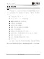
Chapter1ProductIntroduction
Overview
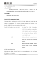
This board is a sort of embedded motherboard compliant with EPIC single board
specification, which is developed basing on the Intel® Atom platform; the board
adopts pin interfaces and is abundant in integration functions, complete in
performanceandhighinreliability;itsmainfeaturesareasfollows:
◆ Support ATOMN270CPU;
◆ Intel®945GSE+Intel®ICH7Mchipset;
◆ Onboard512MBDDR2 memory(couldbeexpandedto 1GB);
◆ Support VGA and LVDSdualdisplayfunction;
◆ Providesix USB2.0 highspeedinterfaces;
◆ Provideone 10/100/1000Mbps Ethernetcontroller;
◆ ProvideoneHDA audiointerface;
◆ Provide two SATA harddiskinterfacesandoneCF cardinterface;
◆ Provide eight COMs, four of which support RS232 and the other four
supportthreeline TTL level;
◆ Provideone MiniPCIEinterface;
◆ Provideone4bitinputand4bitoutputdigitalI/Ointerface;
◆ Single 5V power.
In addition, it also provides one multifunction interface with
keyboard/mouse/buzzer/reset functions and watchdog timer function. This product
could be widely used in the fields like medical monitor, analysis instrument and
electricpowerinspectionandmilitaryindustry.

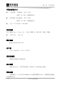
Chapter1ProductIntroduction
2 EC41812CLDNA
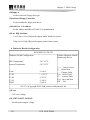
EnvironmentandMechanicalDimension
l OperatingEnvironment:OperatingTemperature: 20℃~60℃;
Humidity: 5%~95%,noncondensing;
l StorageEnvironment:StorageTemperature: 40°C~80°C;
Humidity: 5%~95%,noncondensing;
l Dimension: 115.00mmx165.00mm
PowerConsumption
CPU: onboardIntel®Atom1.6G
Memory: onboard1G (or512M) DDR2533MHz
l +5V@2.8A; +5%/3%;
Microprocessor
ATOMN270CPU;
Chipsets
Intel® 945GSE+Intel® ICH7M;
SystemMemory
512MB or 1GBDDR2 memoryonboard;
VideoFunction
Intel®945GSEintegratesinsystem chip andsupport VGAandLVDS dualdisplay
function.
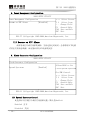
Net workFunct ion
The motherboard integrates one 10/100/1000Mbps Ethernet controller RTL8111C,
whichprovidesyouwithhighspeedandstablenetworkplatform.

Chapter1ProductIntroduction
EC41812CLDNA 3
AudioFunction
IntegrateonestandardHDA audiochipandprovideexcellentsoundeffect.
CF Card
Provide one Compact Flash card interface, which is easy to use and its storage
capacity willvarywiththecard inuse.
SATA Function
Two SATA hard disk interface, speed 3.0Gb/s(when using onboard SATA power
interface to supply power for SATA hard disk, only 2.5″ SATA hard disk is
supported; when using external power, both 2.5″ hard disk and 3.5″ hard disk are
supported).
PowerFeature
Single +5V powersupply;
ExpansionBus
One MiniPCIEinterface;
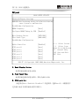
I/OFunctions
● Supporteight COMs,fourofwhichareRS232 interfaceswhiletheother
fourarethreelineTTLinterface;
● Supportsix USB2.0 interfaces;
● Onekeyboard/mouse/buzzer/RESET functioninterface;
● One4bitinput4bitoutputdigitalI/Ointerface.
WatchdogFunction
● 1~255m/sprogrammable;
● Overtimeinterrupt orsystemreset.

Chapter 2 Installation
4 EC41812CLDNA
Chapter2Installation
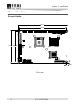
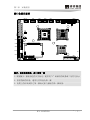
ProductOutline
154.84
165.00
104.85
5.08
5.08
115.00
Unit: mm

Chapter2Installation
EC41812CLDNA 5
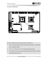
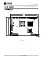
LocationsofInte rfaces
AUDIO1 LAN1 USB3
USB2 USB1
VGA1
LVDS2
LVDS1
LCDB1
JLCDB1
JLCD1
PWR1
MPCIE1
J1
LED2
COM1
COM3
JCC1
GPIO1
COM2
COM4
COM6
COM5
JCF1
SATA1
SATA2
CF1
Tip:Howtoidentifythefirstpinofthejumpersandinterfaces
1. Observetheletterbesidethesocket,itwouldbemarkedwith“1”orthickened
linesortriangularsymbols;
2. Observethesolderpadontheback, thesquarepadisthefirstpin;
3. Theredline onthecableorothermarksshowsthatthey shouldbe connected
withthefirstpinofthesocket.

Chapter 2 Installation
6 EC41812CLDNA
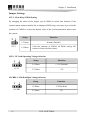
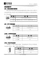
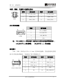
JumperSettings
JCC1:Clear/Keep CMOS Setting
By changing the status of the jumper cap of CMOS to realize this function. If the
systemcannotstartupnormallyduetoimproperBIOSsetup,usersmaytrytoclear the
contentsofCMOS to restore the defaultvalueofthe system parameters andrestart
thesystem.
Setup Function
12Open Normal(Default)
JCC1
12Short
Clear the contents of CMOS, all BIOS setting will
restoretofactorydefaultvalues.
JCF1:CFCard OperatingVoltageSelecti on
Setup Function
12Short +3.3V (Default)
JCF1
23Short +5V
JLCDB1:LVDS B acklightVoltageSelection
Setup Function
12Short +12V(Default)
JLCDB1
23Short +5V

Chapter2Installation
EC41812CLDNA 7
JLCD1: LVDS OperatingVoltageSelection
Theboardprovidestwovoltageoptions,3.3Vand5V.OnlywhentheselectedLCD
voltage is in accord with the LCD voltage in use, the LCD screen could display
normally.
Setup Function
12Short +3.3V (Default)
JLCD1
23Short +5V
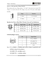
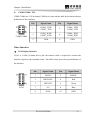
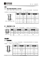
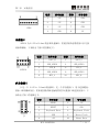
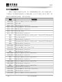
InterfaceforPower,HardDisk,WirelessNetworkCardIndicators
Pin SignalName Pin SignalName
1 FP_IDE_LED 2 FP_IDE_LED+
3 POWER_LED 4 POWER_LED+
LED2
5 WLAN_LED 6 WLAN_LED+
LVDSBacklightControl
Pin SignalName
1 VCC_LCDBKLT
2 LCD_BKLTCTL
3 LCD_BKLTEN
LCDB1
4 GND
Note: VCC_LCDBKLTbacklight power (power voltage is controlled by the
backlightvol tageselectingjumper);
LCD_BKLTCTLbacklightcontrol;
LCD_BKLTEN backlightenabling.

Chapter 2 Installation
8 EC41812CLDNA
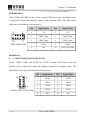
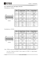
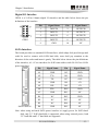
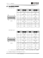
USBInte rface
USB1,USB2andUSB3arethe2×5Pin(2.0mm)USBdevicepins;thetransfercable
is required to connect the interface signals to the standard socket. The table below
showsthepin definitionsoftheinterfaces.
Pin SignalName Pin SignalName
1 +5V 2 +5V
3 USB1_Data 4 USB2_Data
5 USB1_Data+ 6 USB2_Data+
7 GND 8 GND
USB1/USB2/USB3
9 NA 10 GND_CHASSIS
SerialPort
1) COM1/COM2/COM3/COM4:RS232
COM1, COM2, COM3 and COM4 are 2×5Pin (2.0mm) COM device pins; the
transfercableisrequiredtoconnecttheinterfacesignalstothestandardsocket.The
tablebelowshowsthepindefinitionsoftheinterfaces.
Pin SignalName Pin SignalName
1 DCD# 2 RXD
3 TXD 4 DTR#
5 GND 6 DSR#
7 RTS# 8 CTS#
COM1/COM2/COM3/COM4
9 RI# 10 NA

Chapter2Installation
EC41812CLDNA 9
2) COM5/COM6: TTL
COM5/COM6 are2×3Pin (0mm)COMdevicepinsandthetablebelowshowsthepin
definitionsoftheinterfaces.
Pin SignalName Pin Si gnalName
1
COM5_TXD/
COM7_TXD
2
COM6_TXD/
COM8_TXD
3
COM5_RXD/
COM7_RXD
4
COM6_RXD/
COM8_RXD
COM5/COM6
5 GND 6 GND
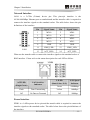
VideoInterface
1) VGADisplayInterface
VGA1 is 2×5Pin (2.0mm) device pin; the transfer cable is required to connect the
interfacesignalstothestandardsocket.Thetablebelowshowsthepindefinitionsof
theinterface.
Pin SignalName Pin SignalName
1 VSYNC 2 HSYNC
3 DDCDATA 4 Red
5 DDCCLK 6 Green
7 +5V 8 Blue
VGA1
9 GND 10 GND

Chapter 2 Installation
10 EC41812CLDNA
2) 36bitDualscan LVDSDisplayInterface
Pindefinitions of LVDS1:
Pin SignalName Pin SignalName
1 LVDS0_D0+ 2 LVDS0_D0
3 GND 4 GND
5 LVDS0_D1+ 6 LVDS0_D1
7 GND 8 GND
9 LVDS0_D2+ 10 LVDS0_D2
11 GND 12 GND
13 LVDS0_CLK+ 14 LVDS0_CLK
15 GND 16 GND
17 NC 18 NC
LVDS1
19 VDD 20 VDD
Pindefinitionsof LVDS2:
Pin SignalName Pin SignalName
1 LVDSE_D0+ 2 LVDSE_D0
3 GND 4 GND
5 LVDSE_D1+ 6 LVDSE_D1
7 GND 8 GND
9 LVDSE_D2+ 10 LVDSE_D2
11 GND 12 GND
13 LVDSE_CLK+ 14 LVDSE_CLK
15 GND 16 GND
17 NC 18 NC
LVDS2
19 VDD 20 VDD
Note: LVDS0xrepresentstheoddlineofdualscan PANEL; LVDSExrepresentsthe
even line of dualscan PANEL. Please connect to LVDS1 if a singlechannel
LCDscreen isused.

Chapter2Installation
EC41812CLDNA 11
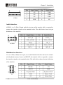
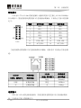
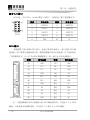
Net workInterface
LAN1 is a 2×7Pin (2.0mm) device pin. This pinstyle interface is the
10/100/1000MbpsEthernetportonmotherboardandthetransfercableisrequiredto
connect the interface signals tothestandardsocket. The table below showsthe pin
definitionsoftheinterface.
Pin SignalName Pin SignalName
1 MX0+ 2 MX0
3 MX1+ 4 MX1
5 MX2+ 6 MX2
7 MX3+ 8 MX3
9 GND 10 GND
11 LINK_LED+ 12 LINK_LED
LAN1
13 ACT_LED+ 14 ACT_LED
Whenuse thetransfercabletoconnecttheinterfacesignalstothestandard socketof
RJ45interface. PleaserefertothestatusdescriptionforeachLED asfollow:
LILED
(DualCol or:Y/G)
LANSpeed
Indicator
ACTLED
(SingleGreen)
LANActivity
Indicator
Green 1000Mbps
Flash DataTransmitting Yellow 100Mbps
Off NoDatatoTransmit Off 10Mbps
PowerInterface
PWR1isa1×8Pinpowerdevicepinandthetransfercableisrequiredtoconnectthe
interfacesignalstothestandardsocket.Thetablebelowshowsthepindefinitionsof
theinterface.

Chapter 2 Installation
12 EC41812CLDNA
Pin SignalName Pin SignalName
1 +5V 5 GND
2 +5V 6 GND
3 +5V 7 GND
PWR1
4 GND 8 NC
AudioInterface
AUDIO1isa2×5Pin(2.0mm)audiodevicepinandthetransfercableisrequiredto
connect the interface signals tothestandardsocket. The table below showsthe pin
definitionsoftheinterface.
MultifunctionI nterface
J1isa2×5Pin(2.0mm)devicepin;itisamultifunctioninterfaceandusedtoconnect
withkeyboard, mouse, buzzer andRESET;thetransfercable isrequired toconnect
theinterfacesignalstothestandardsocket.Thetablebelowshowsthepindefinitions
oftheinterface.
Pin SignalName Pin SignalName
1 SPEAK 2 +5V
3 RESET 4 GND
5 KeyboardData 6 KeyboardClock
7 GND 8 Mouse Clock
J1
9 +5V 10 Mouse Data
Pin SignalName Pin SignalName
1 LOUT_R 2 LOUT_L
3 GND_AUDIO 4 GND_AUDIO
5 LIN_R 6 LIN_L
7 GND_AUDIO 8 GND_AUDIO
AUDIO1
9 MIC_L 10 MIC_R

Chapter2Installation
EC41812CLDNA 13
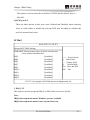
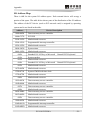
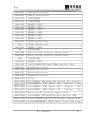
DigitalI/OInterface
GPIO1 isa2×5Pin(2.0mm)digitalI/Ointerface andthetablebelowshows thepin
definitionsoftheinterface.
SATA Interface
TheboardprovidestwostandardSATA interfaces,whichadoptfoolproofdesignand
could be used to connect with SATA hard disk; users shall pay attention to the
directionofthesocketandinsertitgently.Thetablebelowshowsthepindefinitions
oftheinterface,A1~A7areinterfacesforSATAdatacableswhileB1~B15areSATA
powerinterfaces.
Pin SignalName Pin SignalName
A1 GND B5 GND
A2 TX+ B6 GND
A3 TX B7 +5VL
A4 GND B8 +5V
A5 RX B9 +5V
A6 RX+ B10 GND
A7 GND B11 NC
B1 NC B12 GND
B2 NC B13 NC
B3 NC B14 NC
SATA1/SATA2
B4 GND B15 NC
Note: when using onboard SATA power interface to supply power for SATA hard
disk,only2.5″SATAharddiskissupported;whenusingexternalpower,both
2.5″harddiskand3.5″harddiskaresupported.
Pin SignalName Pin SignalName
1 INPUT0 2 OUTPUT0
3 INPUT1 4 OUTPUT1
5 INPUT2 6 OUTPUT2
7 INPUT3 8 OUTPUT3
GPIO1
9 GND 10 NC

Chapter 2 Installation
14 EC41812CLDNA
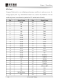
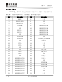
CF Card
CompactFlashcardisasortofhighspeedmemory,smallinsizeandeasytouse.Its
storagecapacitywillvarywithdifferentcardsinuse,suchas1M,256Metc.CFcard
couldonlyinsertinonedirection(markedasCF1 onthebackofboard).
Pin SignalName Pin SignalName
1 GND 26 NC
2 D3 27 D11
3 D4 28 D12
4 D5 29 D13
5 D6 30 D14
6 D7 31 D15
7 CS0# 32 CS1#
8 GND 33 NC
9 GND 34 IOR#
10 GND 35 IOW#
11 GND 36 WE#
12 GND 37 IRQ
13 VCC 38 VCC
14 GND 39 CSEL#
15 GND 40 NC
16 GND 41 RESET#
17 GND 42 IORDY
18 A2 43 DREQ
19 A1 44 DACK#
20 A0 45 DASP#
21 D0 46 ATA66_DET
22 D1 47 D8
23 D2 48 D9
24 WP/IOCS16# 49 D10
25 NC 50 GND

Chapter2Installation
EC41812CLDNA 15
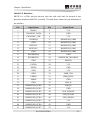
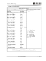
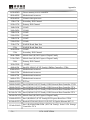
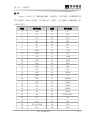
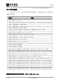
MiniP CIEInterface
MPCIE1 is a 52Pin wireless network card; the card could only be inserted in one
direction(markedasMPCIE1onboard).Thetablebelowshowsthepindefinitionsof
theinterface.
Pin SignalName Pin SignalName
1 WAKE# 2 3.3V
3 CHANNEL_DATA 4 GND
5 CHANNEL_CLK 6 1.5V
7 CLKREQ# 8 RESERVED_SIM4
9 GND 10 RESERVED_SIM3
11 REFCLK 12 RESERVED_SIM2
13 REFCLK+ 14 RESERVED_SIM1
15 GND 16 RESERVED_SIM0
17 RESERVED0 18 GND
19 RESERVED1 20 RESERVED_DISABLE#
21 GND 22 PERST#
23 PETN0 24 3.3V
25 PETP0 26 GND
27 GND 28 1.5V
29 GND 30 SMB_CLK
31 PERN0 32 SMB_DATA
33 PERP0 34 GND
35 GND 36 USB_D
37 RESERVED_PCIE0 38 USB_D+
39 RESERVED_PCIE1 40 GND
41 RESERVED_PCIE2 42 LED_WWAN#
43 RESERVED_PCIE3 44 LED_WLAN#
45 RESERVED_PCIE4 46 LED_WPAN#
47 RESERVED_PCIE5 48 1.5V
49 RESERVED_PCIE6 50 GND
51 RESERVED_PCIE7 52 3.3V

Chapter 3 BIOS Setup
16 EC41812CLDNA
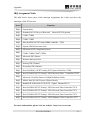
Chapter3 BIOSSetup
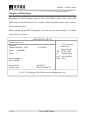
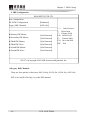
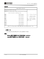
Regarding the BIOS features setup of EC41812CLDNA, please refer to the AMI
BIOSSetupGuide editedbyEVOCCompany.Whilethedifferent part,pleasereferto
thedescriptionsbelow.
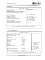
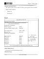
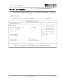
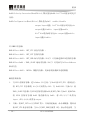
When starting up the SETUP program, you may see the main interface of CMOS
SetupUtility asfollows:
BIOSSETUPUTILITY
SystemOverview
Processor
Genuine Intel(R) CPU @ 2.40GHz
Speed :2400MHz
Cores :1
SystemMemory
Size: 504MB
SystemTime [00:47:55]
SystemDate [Wed03/30/2007]
←→ SelectScreen
↑↓ SelectItem
+ ChangeField
Tab SelectField
F1 GeneralHelp
F10 SaveandExit
ESC Exit
V02.57(c)Copyright19852004,AmericanMegatrends,Inc.
ページが読み込まれています...
ページが読み込まれています...
ページが読み込まれています...
ページが読み込まれています...
ページが読み込まれています...
ページが読み込まれています...
ページが読み込まれています...
ページが読み込まれています...
ページが読み込まれています...
ページが読み込まれています...
ページが読み込まれています...
ページが読み込まれています...
ページが読み込まれています...
ページが読み込まれています...
ページが読み込まれています...
ページが読み込まれています...
ページが読み込まれています...
ページが読み込まれています...
ページが読み込まれています...
ページが読み込まれています...
ページが読み込まれています...
ページが読み込まれています...
ページが読み込まれています...
ページが読み込まれています...
ページが読み込まれています...
ページが読み込まれています...
ページが読み込まれています...
ページが読み込まれています...
ページが読み込まれています...
ページが読み込まれています...
ページが読み込まれています...
ページが読み込まれています...
ページが読み込まれています...
ページが読み込まれています...
ページが読み込まれています...
ページが読み込まれています...
ページが読み込まれています...
ページが読み込まれています...
ページが読み込まれています...
ページが読み込まれています...
ページが読み込まれています...
ページが読み込まれています...
ページが読み込まれています...
ページが読み込まれています...
ページが読み込まれています...
ページが読み込まれています...
ページが読み込まれています...
ページが読み込まれています...
-
 1
1
-
 2
2
-
 3
3
-
 4
4
-
 5
5
-
 6
6
-
 7
7
-
 8
8
-
 9
9
-
 10
10
-
 11
11
-
 12
12
-
 13
13
-
 14
14
-
 15
15
-
 16
16
-
 17
17
-
 18
18
-
 19
19
-
 20
20
-
 21
21
-
 22
22
-
 23
23
-
 24
24
-
 25
25
-
 26
26
-
 27
27
-
 28
28
-
 29
29
-
 30
30
-
 31
31
-
 32
32
-
 33
33
-
 34
34
-
 35
35
-
 36
36
-
 37
37
-
 38
38
-
 39
39
-
 40
40
-
 41
41
-
 42
42
-
 43
43
-
 44
44
-
 45
45
-
 46
46
-
 47
47
-
 48
48
-
 49
49
-
 50
50
-
 51
51
-
 52
52
-
 53
53
-
 54
54
-
 55
55
-
 56
56
-
 57
57
-
 58
58
-
 59
59
-
 60
60
-
 61
61
-
 62
62
-
 63
63
-
 64
64
-
 65
65
-
 66
66
-
 67
67
-
 68
68


