


Dear Customers,
Thank you for choosing this innovative IVS DVR, one series of IVS system products.
From this moment, you are entering into a new era of security guard, and more
convenient and surprising features are presented to suit your versatile needs.
IVS DVR series is integrated with the mobile technology to not only realize the
instance of event notifications, but also increase the mobility of surveillance.
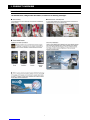
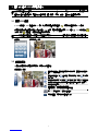
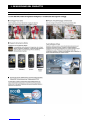
For powerful mobile surveillance support, our self-developed mobile phone
program, “EagleEyes”, compatible on many popular mobile platforms, such as
iPhone®, BlackBerry®, Nokia® Symbian®, Windows® Mobile & Android™, is free
to download from your mobile phone for remote access and device control.
In addition to mobile phones, remote access via different PC software is also
widely supported:
For web browsers, Internet Explorer®, Mozilla® Firefox®, Safari®, Google Chrome™
& Opera are supported.
Apple’s media player, QuickTime®, is also one tool you can use.
Above all, our powerful CMS software allows you to centrally manage multiple
devices in one interface and control all situations.
To know more about IVS system and EagleEyes, and where to download EagleEyes,
please visit:
http://www.eagleeyescctv.com
To know more about feature applications, please visit:
http://www.eagleeyescctv.com/video
To check what’s new about our products, please join:
http://www.eagleeyescctv.com/facebook
To give us your precious suggestions and comments, please contact:


IMPORTANT SAFEGUARD
CAUTION
RISK OF ELECTRIC SHOCK
CAUTION:
To reduce the risk of electric shock, do not expose this apparatus to rain or moisture. Only operate this apparatus
from the type of power source indicated on the label. The company shall not be liable for any damages arising out
of any improper use, even if we have been advised of the possibility of such damages.
The lightning flash with arrowhead symbol, within an equilateral triangle, is intended to alert the user to the presence of
uninsulated “dangerous voltage” within the product’s enclosure that may be of sufficient magnitude to constitute a risk of electric
shock to persons.
This exclamation point within an equilateral triangle is intended to alert the user to the presence of important operating and
maintenance (servicing) instructions in the literature accompanying the appliance.
All lead-free products offered by the company comply with the requirements of the European law on the Restriction of Hazardous
Substances (RoHS) directive, which means our manufacture processes and products are strictly “lead-free” and without the
hazardous substances cited in the directive.
The crossed-out wheeled bin mark symbolizes that within the European Union the product must be collected separately at the
product end-of-life. This applies to your product and any peripherals marked with this symbol. Do not dispose of these products as
unsorted municipal waste. Contact your local dealer for procedures for recycling this equipment.
This apparatus is manufactured to comply with the radio interference requirements.
Federal Communications Commission Interference Statement
This equipment has been tested and found to comply with the limits for a Class A digital device, pursuant to Part 15 of the FCC Rules. These
limits are designed to provide reasonable protection against harmful interference when the equipment is operated in a commercial environment.
This equipment generates, uses, and can radiate radio frequency energy and, if not installed and used in accordance with the instruction manual,
may cause harmful interference to radio communications. Operation of this equipment in a residential area is likely to cause harmful interference
in which case the user will be required to correct the interference at his own expense.
This device complies with Part 15 of the FCC Rules. Operation is subject to the following two conditions:
(1) this device may not cause harmful interference, and
(2) this device must accept any interference received, including interference that may cause undesired operation.
Trademark Acknowledgements
and (EagleEyes) - The trademark application is filed and under process in the U.S. and other countries.
iPhone® is the registered trademark of Apple Inc., and Apple holds the intelligential property rights to the iPhone content.
BlackBerry® and related trademarks, names and logos are the property of Research In Motion Limited and are registered and/or used in the U.S.
and countries around the world. Used under license from Research In Motion Limited.
Android™ is a trademark of Google Inc. Use of this trademark is subject to Google Permissions.
Microsoft®, Windows®, Internet Explorer®, Mozilla® Firefox®, Google Chrome™, Safari®, QuickTime®, Windows® Mobile & Symbian®
mentioned in this document are the registered trademarks of their respective holders.
Disclaimer
The information in this manual was current when released. We reserve the right to revise or remove any content in this manual at any time. We
do not warrant or assume any legal liability or responsibility for the accuracy, completeness, or usefulness of this manual. For the actual display
& operation, please refer to your DVR in hand. The content of this manual is subject to change without notice.
Grounding
This is a Safety Class 1 Product (provided with a protective earthing ground incorporated in the power cord). The mains plug shall only be
inserted in a socket outlet provided with a protective earth contact. Any interruption of the protective conductor inside or outside of the instrument
is likely to make the instrument dangerous. Intentional interruption is prohibited.
Water & Moisture
Do not expose this product to dripping or splashing and that no objects filled with liquids, such as vases, shall be placed on the product.

MPEG4 Licensing
THIS PRODUCT IS LICENSED UNDER THE MPEG-4 VISUAL PATENT PORTFOLIO LICENSE FOR THE PERSONAL AND
NON-COMMERCIAL USE OF A CONSUMER FOR (i) ENCODING VIDEO IN COMPLIANCE WITH THE MPEG-4 VISUAL STANDARD
(“MPEG-4 VIDEO”) AND/OR (ii) DECODING MPEG-4 VIDEO THAT WAS ENCODED BY A CONSUMER ENGAGED IN A PERSONAL AND
NON-COMMERCIAL ACTIVITY AND/OR WAS OBTAINED FROM A VIDEO PROVIDER LICENSED BY MPEG LA TO PROVIDE MPEG-4
VIDEO. NO LICENSE IS GRANTED OR SHALL BE IMPLIED FOR ANY OTHER USE. ADDITIONAL INFORMATION INCLUDING THAT
RELATING TO PROMOTIONAL INTERNAL AND COMMERCIAL USES AND LICENSING MAY BE OBTAINED FROM MPEG LA, LLC. SEE
HTTP://WWW.MPEGLA.COM.
GPL Licensing
This product contains codes which are developed by Third-Party-Companies and which are subject to the GNU General
Public License (“GPL”) or the GNU Lesser Public License (“LGPL”).
The GPL Code used in this product is released without warranty and is subject to the copyright of the corresponding
author.
Further source codes which are subject to the GPL-licenses are available upon request.
We are pleased to provide our modifications to the Linux Kernel, as well as a few new commands, and some tools to get
you into the code. The codes are provided on the FTP site, and please download them from the following site or you
can refer to your distributor:
http://download.dvrtw.com.tw/GPL/076D_Series/arm-linux-2.6.tar.gz

TABLE OF CONTENTS
1. PRODUCT OVERVIEW ..................................................................................................................... 1
2. CONNECTION AND SETUP.............................................................................................................. 2
2.1 Prerequisites ..........................................................................................................................................................2
2.2 SATA HDD Installation............................................................................................................................................2
2.3 Installing DCCS Camera........................................................................................................................................3
2.4 Connecting DCCS Camera....................................................................................................................................4
2.5 DVR Power On ......................................................................................................................................................4
2.6 Date and Time Setting............................................................................................................................................4
2.7 Clear Hard Disk......................................................................................................................................................5
2.8 Password Setting ...................................................................................................................................................5
2.9 Examining Signal Transmission .............................................................................................................................6
2.10 Configuring DCCS Camera..................................................................................................................................6
2.10.1 For a PTZ camera.....................................................................................................................................6
2.10.2 For a zoom lens control camera................................................................................................................7
3. GUI DISPLAY WITH USB MOUSE CONTROL ................................................................................. 8
3.1 Connect USB Mouse..............................................................................................................................................8
3.2 Quick Menu Bar .....................................................................................................................................................8
3.3 Main Menu .............................................................................................................................................................9
4. FRONT AND REAR PANELS.......................................................................................................... 11
4.1 Front Panel ..........................................................................................................................................................11
4.2 Rear Panel ...........................................................................................................................................................12
5. BASIC OPERATION ........................................................................................................................ 13
5.1 Live Page.............................................................................................................................................................13
5.2 Record Icon..........................................................................................................................................................13
5.3 Playback ..............................................................................................................................................................13
Playback Control................................................................................................................................................14
Event Search .....................................................................................................................................................14
Audio Playback ..................................................................................................................................................14
5.4 User Level Switch ................................................................................................................................................15
5.5 VGA Output Resolution Support ..........................................................................................................................15
5.6 System Sources Reallocation (For AVC794C / 793C / 793CD Only) .............................................................................16
APPENDIX 1. GRAPHICAL OSD TABLE ........................................................................................... 17
APPENDIX 2. SET IPHONE PUSH NOTIFICATION ........................................................................... 18
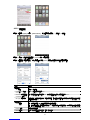
A2.1 Prerequisite .......................................................................................................................................................18
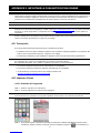
A2.2 Set iPhone.........................................................................................................................................................18
A2.2.1 Program Download.................................................................................................................................18
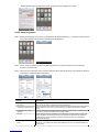
A2.2.2 Program Setup .......................................................................................................................................19
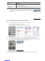
A2.2.3 Push Notification On...............................................................................................................................20
APPENDIX 3. SET FLOW COUNTING / VIRTUAL FENCE / ONE WAY ............................................ 21
A3.1 IVS APPLICATION.............................................................................................................................................22
A3.1.1 FLOW COUNTING .................................................................................................................................22
A3.1.2 VIRTUAL FENCE and ONE WAY ...........................................................................................................23
A3.2 IVS STATISTICS................................................................................................................................................24


2
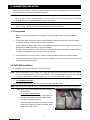
2. CONNECTION AND SETUP
Before the DVR is powered on, make sure you have installed a hard disk, connected at least one camera and a
monitor. For details, please refer to the following sections.
Note: The DVR is designed to automatically detect the video system of the connected cameras (NTSC or
PAL). To make sure the system detection is correct, please check if the cameras are connected to
the DVR and power-supplied before the DVR is powered on.
Note: The connection and setup described below are for DCCS devices only. For details about connecting
cameras other than DCCS ones, please refer to the DVR user manual.
2.1 Prerequisites
Make sure your cameras support the DCCS function. For details, please check with your distributor or
installer.
To ensure the signal transmission, the recommended distance between this DVR and cameras should not
exceed 200 meters by using 3C2V coaxial cables (112 braids).
However, different materials used in 3C2V coaxial cables with different connection distance may cause some
effects for the availability and fluency of signal transmission.
Therefore, please do the DCCS test as instructed in “2.9 Examining Signal Transmission” at page 6 when the
connection is completed to ensure this system can work normally.
It’s not allowed to use a signal booster or modem to amplify signals and extend the connection distance.
The DCCS function doesn’t support the channel which is looped from a DCCS camera connected to the same
DCCS DVR or to other DCCS DVR.
2.2 SATA HDD Installation
A SATA HDD must be installed before the DVR is powered on.
Note: It’s recommended to clear all data in the hard disk when the DVR is powered on and the date &
time are set correctly to ensure the recorded data are not mixed with other data previously saved
in the same hard disk. For details, please refer to “2.7 Clear Hard Disk” at page 5.
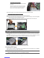
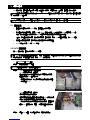
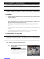
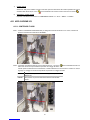
For AVC799B & AVC797B
Step1: Loose the screws on the upper cover and open the upper cover of the DVR.
Note: The DVR cover is made of metal. Please be careful with its edge when you remove the cover.
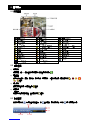
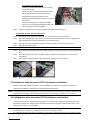
Step2: There are two HDD brackets for this DVR as indicated on
the right picture.
2-1 To install on the first bracket
Remove the bracket, and align the screw holes of the
bracket with the HDD’s screw holes. Make sure the
PCB side of the HDD is facing up.
Fasten the HDD to the bracket, and connect the power
connector and data bus connector to the HDD. Then,
replace the bracket to DVR.

3
2-2 To install on the second bracket
Connect the power connector and data bus connector
to the HDD.
Align the screw holes of the bracket with the HDD’s
screw holes. Make sure the PCB side of the HDD is
facing up. Then, fasten the HDD to the bracket.
Step3: Close the upper cover of the DVR, and fasten all the screws you loosened in Step1.
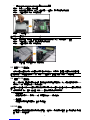
For AVC794B, AVC794C, AVC793C & AVC793CD
Step1: Remove the screws on the top cover of DVR, and remove the top cover.
Step2: Remove the HDD bracket as indicated below. Then, with the PCB side facing up, connect the compatible
HDD to the power connector and data bus connector.
Step3: Put the compatible HDD in the bracket, and fasten it with the supplied screws, two for each side.
Step4: Replace the bracket back to the DVR.
Note: Step5 ~ 7 are applicable for AVC794B, AVC794C & AVC793C Only.
Step5: For installing another HDD, find the supplied HDD brackets in the package, and fix them onto the DVR
base.
Step6: With the PCB side facing up, connect the compatible HDD to the power connector and data bus connector.
Step7: Then, put the HDD in the bracket, and fasten it with the supplied screws, two for each side.
Step8: Replace the top cover and fasten the screws you loosened in Step1.
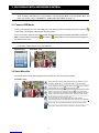
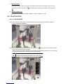
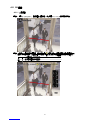
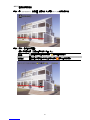
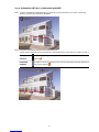
2.3 Installing DCCS Camera
Install the camera on the wall or ceiling based on your installation environment and camera type. For installation
details, please refer to the user manual of your camera.
Note: The distance between the camera and DVR needs to be within 200 meters for DCCS control to take
effects. For details, please refer to “2.1 Prerequisites” at page 2.

4
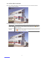
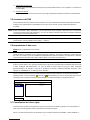
2.4 Connecting DCCS Camera
The cameras must be connected and power-supplied before the DVR is powered on. Connect the camera with
the indicated power supply. Then, connect the camera video output to the DVR video input port with a coaxial
cable or RCA cable with BNC connectors.
Note: For AVC799B, only channel 1 ~ 4 support DCCS camera connection;
For AVC797B, only channel 1 & 2 support DCCS camera connection;
For AVC794B, AVC794C, AVC793C and AVC793CD, only channel 1 supports DCCS camera
connection.
1) Video cable connection
Connect the camera video output to the DVR video input port with a coaxial cable or RCA cable with BNC
connector.
2) Power connection
Connect the camera with indicated power supply and make sure it’s power-supplied.
2.5 DVR Power On
This device should be operated only with the type of power source indicated on the manufacturer’s label. Connect
the indicated AC power cord to the power adapter, and plug into an electrical outlet. The power LED will be on.
Note: Before the DVR is powered on, make sure (1) the cameras are connected and power-supplied for
the detection of the camera video system to be correct, and (2) a monitor (either LCD or CRT
monitor) is connected to the DVR for correct video output detection.
Note: To ensure that your DVR works constantly and properly, it's recommended to use an UPS,
Uninterruptible Power Supply (Optional), for continuously operation.
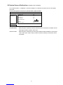
2.6 Date and Time Setting
Before operating your DVR, please set the date and time on your DVR FIRST.
Note: Please DO NOT change the date or time of your DVR after the recording function is activated.
Otherwise, the recorded data will be disordered and you will not be able to find the recorded file
to backup by time search. If users change the date or time accidentally when the recording
function is activated, it’s recommended to clear all HDD data, and start recording again.
Note: For the first time to use the DVR, please power it on for at least 48 hours continuously after the
date & time is set correctly. It helps to prevent DVR time from resetting after the disconnecting of
DVR power. If the DVR time resets after the disconnecting of DVR power, for example, caused by
a power outage, the battery might run out and please replace the battery as described in
“APPENDIX 6” in the DVR user manual.
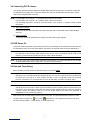
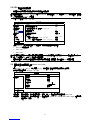
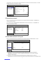
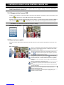
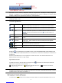
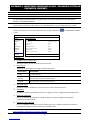
Right-click to enter the DVR password with the password keypad. The default administrator password is 0000.
The status will be changed from (key lock) to (administrator). Then, right-click to show the main menu,
and select “QUICK START” “TIME SETUP” to set the date & time.

5
QUICK START
GENERAL DATE 2009 / NOV / 17
TIME SETUP TIME 15 : 35 : 53
EXIT
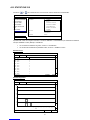
2.7 Clear Hard Disk
It’s recommended to clear all data in the hard disk for the first time to user this DVR to ensure the recorded data
are not mixed with other data previously saved in the same hard disk.
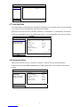
Right-click to show the main menu, and select “SYSTEM” “SYSTEM INFO” “CLEAR HDD”. The DVR will
reboot when HDD data are cleared. For details, please refer to “5.3.2 SYSTEM INFO” in the DVR user manual.
SYSTEM
TOOLS BAUD RATE 2400
SYSTEM INFO HOST ID 000
BACKUP DATA (USB) R.E.T.R 5
BACKUP LOG (USB) AUTO KEY LOCK NEVER
CLEAR HDD HDD-0
RESET DEFAULT SUBMIT
REMOTE CONTROL ID 000
SERIAL TYPE RS485
VIDEO FORMAT NTSC
VERSION 1019-1008-1010-1010
EXIT
2.8 Password Setting
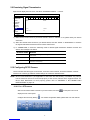
Right-click to show the main menu, and select “SYSTEM” “TOOLS” to change the DVR password.
There are two user levels: ADMIN & OPERATOR. For details, please refer to “5.3.1 TOOLS” in the DVR user
manual.
SYSTEM
TOOLS LANGUAGE ENGLISH
SYSTEM INFO ADMIN PASSWORD SETUP
BACKUP DATA (USB) OPERATOR PASSWORD SETUP
BACKUP LOG (USB) UPGRADE SUBMIT
BACKUP CONFIG SUBMIT
RESTORE CONFIG SUBMIT
EXIT

6
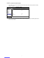
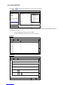
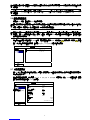
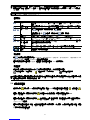
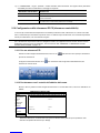
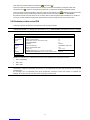
2.9 Examining Signal Transmission
Right-click to display the main menu, and select “ADVANCED CONFIG” “DCCS”.
ADVANCED CONFIG
C A N E R A CH1 CH2 CH3
CH4
CH5
CH6
CH7
CH8
CH9
CH10
CH11 W X
DETECTION
DIAGNOSTIC START
ALERT
MENU SETUP
NETWORK
DISPLAY
RECORD
DEVICES
DCCS DEVICE AVK523
IVS
CONNECTION OK
NOTIFY
EXIT
1) Make sure the model number of your DCCS camera is shown in “DEVICE”. If not, please check your camera
connection.
2) Select the channel which connects to your DCCS camera, and click “START” in “DIAGNOSTIC” to examine
the signal transmission between the DCCS camera and the DVR.
3) In “CONNECTION”, it shows the examining result for DCCS signal transmission between the DVR and
camera. The message is as follows:
MESSAGE SHOWN MEANING
CHECKING The DVR is checking the DCCS signal transmission between the DVR
and camera.
OK The signal transmission is fine and the DCCS function works properly.
FAIL The signal transmission is too weak or not available for the DCCS
function to work properly.
2.10 Configuring DCCS Camera
DCCS cameras have three types: PTZ cameras, zoom lens control cameras, and human detection cameras.
Based on the camera type, different camera settings are needed as described below.
Note: iPhone Push Notification (not applicable for AVC793C and AVC793CD) is available only when a
human detection camera is connected properly to the correct channel which supports DCCS. For
iPhone Push Notification to work properly, please refer to “APPENDIX 2. SET IPHONE PUSH
NOTIFICATION” at page 18.
2.10.1 For a PTZ camera
Switch to the channel which connects to your PTZ camera, and click “ ” on the quick menu bar to
display the PTZ control panel.
Configure the camera by clicking “ ”. For camera configuration details, please refer to its user manual.

7
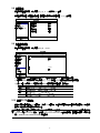
2.10.2 For a zoom lens control camera
In the “DCCS” menu, move to the channel which connects to the zoom lens control camera, and click
“SETUP” in “MENU”.
ADVANCED CONFIG
C A N E R A CH1 CH2 CH3
CH4
CH5
CH6
CH7
CH8
CH9
CH10
CH11 W X
DETECTION
DIAGNOSTIC START
ALERT
MENU SETUP
NETWORK
DISPLAY
RECORD
DEVICES
DCCS DEVICE AVK523
IVS
CONNECTION OK
NOTIFY
EXIT
Different zoom lens control cameras might have different parameter settings. For details, please refer to
their own user manuals.

8
3. GUI DISPLAY WITH USB MOUSE CONTROL
Note: The graphical OSD shown in this document is taking AVC799B, AVC797B, AVC794B and AVC794C
as an example. AVC793C(D) is using another set of graphical OSD. To know details about the
other set, please refer to “APPENDIX 1. GRAPHICAL OSD TABLE” at page 17.
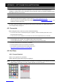
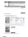
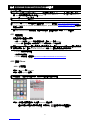
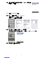
3.1 Connect USB Mouse
Connect your USB mouse to one of the USB ports on the DVR front panel, and check if there’s a mouse icon ( )
on the screen, indicating the USB mouse is detected properly.
Move your mouse to enter the DVR password with the password keypad. The default administrator password is
0000. The status will be changed from (key lock) to (administrator), and the quick menu bar appears on
the left side of the screen.
Note: There are two user levels for DVR access which can be set in the main menu “SYSTEM” “TOOLS”.
For details, please refer to your user manual.
Password Input Quick Menu: Close
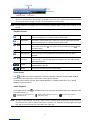
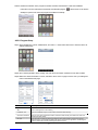
3.2 Quick Menu Bar
Move to the arrow mark to extend the quick menu bar and show the six functions as follows:
Quick Menu: Open
Click to show the channel switch panel and select the channel you want.
For details, please refer to “3.2 Quick Menu Bar” in the user manual.
Click to display the playback control panel, and click to play the latest
recorded video clip, or click to enter the search list.
Switch to the channel you want first, and click to enter the zoom-in
mode. In this mode, click and drag the red frame on the bottom left of the
screen to move to the place you want to see. To exit this mode, click 7.
Click to select the audio channel you want:
In the live mode, only the live audio channels can be selected.
In the playback mode, live and playback audio channels can be selected.
Click to enter the PTZ mode and show the PTZ camera control panel.
Click to show the power off panel to either halt or reboot the system.

9
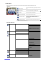
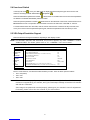
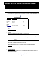
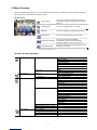
3.3 Main Menu
Right-click anywhere on the screen to show the main menu as follows, and right-click again to exit.
Main Menu
QUICK START Click to set the status display, image settings, and date &
time.
DATE SETUP Click to set the date display and daylight saving.
SYSTEM Click to set the system configurations.
EVENT INFORMATION Click to enter the event search menu.
ADVANCED CONFIG
Click to set CAMERA, DETECTION, ALERT,
NETWORK, DISPLAY, RECORD, DEVICES, DCCS,
IVS* & NOTIFY*.
SCHEDULE SETTING Click to set record timer, detection timer & alarm timer.
* Available for AVC799B, 797B, 794B & 794C only.
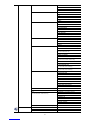
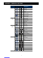
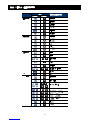
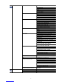
Main Menu Structure
QUICK START GENERAL CHANNEL TITLE
EVENT STATUS
DATE DISPLAY
DCCS DISPLAY
MOUSE SENSITIVITY
PRIORITY (For AVC794C, 793C & 793CD Only)
RECORD CONFIG
TIME SETUP DATE
TIME
DATE SETUP DATE INFO DISPLAY DATE OF MODE
FORMAT
DAYLIGHT DAYLIGHT SAVING
SYSTEM TOOLS LANGUAGE
ADMIN PASSWORD
OPERATOR PASSWORD
UPGRADE
BACKUP CONFIG
RESTORE CONFIG
SYSTEM INFO BAUD RATE
HOST ID
R.E.T.R.
AUTO KEY LOCK
CLEAR HDD
RESET DEFAULT
REMOTE CONTROL ID
SERIAL TYPE
VIDEO FORMAT
VERSION
BACKUP DATA (USB)
BACKUP DATA (DVD) (For 793CD Only)
BACKUP LOG (USB)
EVENT INFORMATION QUICK SEARCH
EVENT SEARCH
HDD INFO
EVENT LOG
ADVANCED CONFIG CAMERA BRIGHTNESS
CONTRAST
SATURATION

10
ADVANCED CONFIG CAMERA HUE
COV.
REC
CHANNEL TITLE
DETECTION LS
SS
TS
MOTION
ALARM
AREA
ALERT EXT. ALERT
INT. BUZZER
KEY BUZZER
VLOSS BUZZER
MOTION BUZZER
ALARM BUZZER
HDD BUZZER
ALARM DURATION (SEC)
HDD NEARLY FULL (GB)
NETWORK NETWORK
SNTP
FTP
E-MAIL
DDNS
DISPLAY DE-INTERLACE (For AVC799B & 797B Only)
FULL SCREEN DURATION
QUAD SCREEN DURATION
(For AVC799B & 797B Only)
CALL SCREEN DURATION
DISPLAY COVERT
HDD DISPLAY MODE
VIDEO OUTPUT
(For AVC794C, AVC793C & 793CD Only)
ALPHA BLENDING
VGA OUTPUT
VGA DEINTERLACE
(For AVC799B, 797B & 794B Only)
COMPOSITE DEINTERLACE
(For AVC799B, 797B & 794B Only)
RECORD MANUAL RECORD
EVENT RECORD
TIMER RECORD
EVENT RECORD IPS
TIMER RECORD IPS
PRE-ALARM RECORD
OVERWRITE
EVENT RECORD ALL CH.
KEEP DATA LIMIT (DAYS)
RECORD CONFIG
DEVICES
DCCS
IVS CAMERA (For AVC799B & 797B Only)
(For AVC799B, 797B, 794B & 794C only) IVS MODE
DISPLAY LINE
SENSITIVITY
RESET COUNT
VIRTUAL FENCE AREA
SCENE CHANGE
SCENE CHANGE LEVEL
NOTIFY (For AVC799B, 797B, 794B & 794C only) GUARD
SCHEDULE SETTING RECORD
DETECTION
ALARM

11
4. FRONT AND REAR PANELS
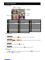
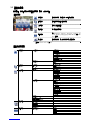
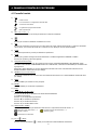
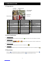
4.1 Front Panel
1) LED Indicators
DVR is powered on.
HDD is reading or recording.
An alarm is triggered.
Timer recording is on.
Under playback status.
2) CH1 ~ 16 / 1 ~ 8 / 1 ~ 4
Press the channel number buttons to select the channel to display.
3)
Press to show the 4 channel display mode.
4) SEQ
Press to display each channel in full screen one by one starting from CH1. When the last channel is displayed, it
will repeat from CH1 again. To exit this mode, press “SEQ” again.
5) SLOW
In the playback mode, press to show slow playback.
6) ZOOM
Press to enlarge the picture of selected channel in the FRAME or FIELD recording mode.
7) LIST (Event List Search)
Press to quickly search the recorded files by event lists: RECORD / MOTION / ALARM / TIME / HUMAN
DETECTION / IVS / STATISTIC, or select FULL to show all the event logs.
To quickly search the time you want, select “QUICK SEARCH”. For details, please refer to “5.4.1 QUICK
SEARCH” in the user manual.
8) SEARCH (For AVC793C & 793CD Only)
Press to enter the time search menu. For details, please refer to “5.4.1 QUICK SEARCH” in the user manual.
9) MENU
Press “MENU” to enter the main menu.
10) ENTER
Press “ENTER” to confirm the setting.
11) PLAY (Z)
Press to playback the latest recorded data.
12) (▲) / (▼) / (◄) / (►)
Press ▲ / ▼ / ◄ / ► to move up / down / left / right.
In the playback mode:
Press “” to pause playback.
Press “” to stop playback.
Press ““ to fast forward.
Press ““ to fast rewind.
13) AUDIO (SLOW + ZOOM)
Press “SLOW” + “ZOOM” to select live or playback audio from audio channel 1~4.
Live audio from audio channel 1~4
(indicated in white). Playback audio from audio channel 1~4
(indicated in yellow).
Audio channel unselected
14) P.T.Z. ( + SEQ)
Press “ ” + “SEQ” at the same time to enter / exit the PTZ control mode.

12
15) USB port
There are two USB ports on the front panel, one for connecting your USB mouse for mouse control, and the other
one for connecting your USB flash drive for video backup.
Note: It’s not allowed to have two USB mice or two USB flash drives connected on the front panel.
Note: For the compatible USB flash drive list, please refer to “APPENDIX 3” in the user manual.
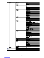
4.2 Rear Panel
1) 75Ω / HI-IMPEDANCE (For AVC799B & 797B Only)
When using Loop function, please switch to HI-IMPEDANCE. When you don’t use Loop function, please switch to
75Ω.
2) VIDEO IN (1 ~ 16 / 1 ~ 8 / 1 ~ 4): Connect to the video connector of a camera.
VIDEO LOOP (1 ~ 16 / 1 ~ 8): Video output connector.
Note: The DVR will automatically detect the video system of the camera, please make sure that the
cameras are properly connected to the DVR and power-supplied before the DVR is turned on.
3) AUDIO IN (1~4)
Connect to the audio connector of a camera if the camera supports audio recording.
Note: To make a video backup with audio, make sure the camera which supports the audio function is
connected to the video-in channel and audio-in channel. For example, the audio data from audio
CH1 will be recorded with the video data from video CH1.
4) AUDIO OUT
Connect to a speaker with 1 mono audio output.
Note: To know how many audio outputs your DVR supports, please refer to its specifications.
5) MONITOR
Connect to a CRT monitor for video output.
Note: While connecting to a CRT monitor, it’s also supported to connect to a LCD monitor simultaneously
for dual video output.
6) CALL
Connect to a monitor specific for sequence display.
7) VGA
Connect to a LCD monitor directly.
Note: While connecting to a LCD monitor, it’s also supported to connect to a CRT monitor simultaneously
for dual video output.
8) IR
Connect the IR receiver extension line for remote control.
9) EXTERNAL I/O
This port is used to connect external devices (such as speed dome cameras or external alarm, etc).
10) LAN
Connect to Internet by LAN cable.
11) DC 19V
Connect to the supplied adapter.
12) Power Switch
Switch to “\” to turn on the power, and “|” to turn off the power.
ページが読み込まれています...
ページが読み込まれています...
ページが読み込まれています...
ページが読み込まれています...
ページが読み込まれています...
ページが読み込まれています...
ページが読み込まれています...
ページが読み込まれています...
ページが読み込まれています...
ページが読み込まれています...
ページが読み込まれています...
ページが読み込まれています...
ページが読み込まれています...
ページが読み込まれています...
ページが読み込まれています...
ページが読み込まれています...
ページが読み込まれています...
ページが読み込まれています...
ページが読み込まれています...
ページが読み込まれています...
ページが読み込まれています...
ページが読み込まれています...
ページが読み込まれています...
ページが読み込まれています...
ページが読み込まれています...
ページが読み込まれています...
ページが読み込まれています...
ページが読み込まれています...
ページが読み込まれています...
ページが読み込まれています...
ページが読み込まれています...
ページが読み込まれています...
ページが読み込まれています...
ページが読み込まれています...
ページが読み込まれています...
ページが読み込まれています...
ページが読み込まれています...
ページが読み込まれています...
ページが読み込まれています...
ページが読み込まれています...
ページが読み込まれています...
ページが読み込まれています...
ページが読み込まれています...
ページが読み込まれています...
ページが読み込まれています...
ページが読み込まれています...
ページが読み込まれています...
ページが読み込まれています...
ページが読み込まれています...
ページが読み込まれています...
ページが読み込まれています...
ページが読み込まれています...
ページが読み込まれています...
ページが読み込まれています...
ページが読み込まれています...
ページが読み込まれています...
ページが読み込まれています...
ページが読み込まれています...
ページが読み込まれています...
ページが読み込まれています...
ページが読み込まれています...
ページが読み込まれています...
ページが読み込まれています...
ページが読み込まれています...
ページが読み込まれています...
ページが読み込まれています...
ページが読み込まれています...
ページが読み込まれています...
ページが読み込まれています...
ページが読み込まれています...
ページが読み込まれています...
ページが読み込まれています...
ページが読み込まれています...
-
 1
1
-
 2
2
-
 3
3
-
 4
4
-
 5
5
-
 6
6
-
 7
7
-
 8
8
-
 9
9
-
 10
10
-
 11
11
-
 12
12
-
 13
13
-
 14
14
-
 15
15
-
 16
16
-
 17
17
-
 18
18
-
 19
19
-
 20
20
-
 21
21
-
 22
22
-
 23
23
-
 24
24
-
 25
25
-
 26
26
-
 27
27
-
 28
28
-
 29
29
-
 30
30
-
 31
31
-
 32
32
-
 33
33
-
 34
34
-
 35
35
-
 36
36
-
 37
37
-
 38
38
-
 39
39
-
 40
40
-
 41
41
-
 42
42
-
 43
43
-
 44
44
-
 45
45
-
 46
46
-
 47
47
-
 48
48
-
 49
49
-
 50
50
-
 51
51
-
 52
52
-
 53
53
-
 54
54
-
 55
55
-
 56
56
-
 57
57
-
 58
58
-
 59
59
-
 60
60
-
 61
61
-
 62
62
-
 63
63
-
 64
64
-
 65
65
-
 66
66
-
 67
67
-
 68
68
-
 69
69
-
 70
70
-
 71
71
-
 72
72
-
 73
73
-
 74
74
-
 75
75
-
 76
76
-
 77
77
-
 78
78
-
 79
79
-
 80
80
-
 81
81
-
 82
82
-
 83
83
-
 84
84
-
 85
85
-
 86
86
-
 87
87
-
 88
88
-
 89
89
-
 90
90
-
 91
91
-
 92
92
-
 93
93


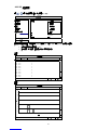
他の言語で
- italiano: IVS System AVC793D Guida d'installazione
- English: IVS System AVC793D Installation guide
その他のドキュメント
-
RadioLink F121 ProFPVTransporter2pdf ユーザーマニュアル
-
Optiview 4CH ユーザーマニュアル
-
Avtech AVH306 ユーザーマニュアル
-
Samsung SCC-C6325N 取扱説明書
-
Samsung SCC-C7478P 取扱説明書
-
-
AKASO Trace 1 Pro Dual Lens Car Dash Camera, 2K Dash Cam WiFi ユーザーマニュアル
-
-
-
AVer DL10 ユーザーガイド