
*
—
—
—
•
•
— Ω Ω
•
•
—
—
—
•
•
•
•
•
*
•
•
•
Fuse Replacement
If the fuse blows, check the power connection and
replace both the fuses. If the fuse blows again after
replacement, there may be an internal malfunction.
In such a case, consult your nearest Sony dealer.
Warning
When replacing the fuse, be sure to use one
matching the amperage stated above the fuse
holder. Never use a fuse with an amperage rating
exceeding the one supplied with the unit as this
could damage the unit.
∗ Protection circuit
This amplifier is provided with a protection circuit
that operates in the following cases:
— when the unit is overheated
— when a DC current is generated
— when the speaker terminals are short-circuited
The PROTECTOR indicator lights up in red and the
unit will shut down.
If this happens, turn off the connected
equipment, take out the cassette tape or disc, and
determine the cause of the malfunction. If the
amplifier has overheated, wait until the unit cools
down before use.
If you have any questions or problems concerning
your unit that are not covered in this manual,
please consult your nearest Sony dealer.
P
R
O
T
E
C
T
O
R
ø 6
142
402
364
275
55
2007 Sony Corporation Printed in Thailand
XM-2002GTR
Precaution
2-666-762-31 (1)
Stereo Power
Amplifier
Operating Instructions
Installation
Before Installation
•Mount the unit either inside the trunk or under a
seat.
•Choose the mounting location carefully so the
unit will not interfere with the normal
movements of the driver and it will not be
exposed to direct sunlight or hot air from the
heater.
•Do not install the unit under the floor carpet,
where the heat dissipation from the unit will be
considerably impaired.
First, place the unit where you plan to install it,
and mark the positions of the four screw holes on
the surface of the mounting board (not supplied).
Then drill the holes approximately 3 mm in
diameter and mount the unit onto the board with
the supplied mounting screws. The supplied
mounting screws are 15 mm long. Therefore, make
sure that the mounting board is thicker than
15 mm.
•
•
•
Specifications
Circuit system OTL (output transformerless)
circuit
Pulse power supply
Inputs RCA pin jacks
High level input connector
Outputs Speaker terminals
Through out pin jacks
Suitable speaker impedance
2 – 8 Ω (stereo)
4 – 8 Ω (when used as a bridging
amplifier)
Maximum outputs 400 W × 2 (at 4 Ω)
600 W × 2 (at 2 Ω)
1,200 W (monaural) at 4 Ω
Rated outputs (supply voltage at 14.4 V)
200 W × 2 (20 Hz – 20 kHz, 0.1 %
THD, at 4 Ω)
250 W × 2 (20 Hz – 20 kHz, 0.15 %
THD, at 2 Ω)
500 W (monaural) (20 Hz – 20
kHz, 0.15 % THD, at 4 Ω)
Frequency response
5 Hz – 50 kHz (
dB)
Input level adjustment range
0.3 – 6.0 V (RCA pin jacks)
1.2 – 12.0 V (High level input)
Low-pass filter 50 – 300 Hz, – 12 dB/oct
Low boost 0 – 10 dB (40 Hz)
Power requirements
12 V DC car battery
(negative ground)
Power supply voltage
10.5 – 16 V
Current drain at rated output: 48 A (at 4 Ω)
Remote input: 1 mA
Dimensions Approx. 402 × 55 × 275 mm
(w/h/d) not incl. projecting parts
and controls
Mass Approx. 5.15 kg not incl.
accessories
Supplied accessories
Mounting screws (4)
High level input cord (1)
Design and specifications are subject to change
without notice.
Features
•Maximum power output of 400 W per channel
(at 4 Ω).
•This unit can be used as a bridging amplifier
with a maximum output of 1,200 W.
•Direct connection can be made with the speaker
output of your car audio unit if it is not equipped
with a line output (High Level Input
Connection).
•Hi-level Sensing power On feature allows unit to
be activated without need for REMOTE
connection.
•Built-in variable LPF (Low-pass filter) and low
boost circuit.
•Dual mode connection possible for a multi-
speaker system.
•Protection circuit.
•Pulse power supply* for stable, regulated output
power.
* Pulse power supply
This unit has a built-in power regulator which
converts the power supplied by the DC 12 V car
battery into high speed pulses using a
semiconductor switch. These pulses are stepped
up by the built-in pulse transformer and
separated into both positive and negative power
supplies before being converted into direct
current again. This light weight power supply
system provides a highly efficient power supply
with a low impedance output.
• Ω
•
•
•
•
•
•
• *
*
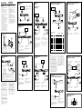
Circuit Diagram
Unit: mm
Low boost
Frequency /
dB
Frequency /
dB
Cut-off frequency (LPF)
Parts for Installation and Connections
12
(× 4)
358
P
R
O
T
E
C
T
O
R
FILTER
OFF
LPF
LEVEL
LOW BOOST
(40Hz)
0 +10dB
6
0.3V
2
4
5.5
0.5
60
50 300Hz
170
110
260
10
10
0
40 100 1k
10
0
-10
-20
-30
-40
-50
-60
-70
-80
10 100 1k
50Hz
170Hz
300Hz
LEVEL
LPF
Normal
AMP
Power
Lch
LEVEL
Inverted
AMP
Power
Rch
BTL.
Lch
Rch
(BTL.)
LOW BOOST
LOW BOOST
ø 5 × 15
Hz
Hz
1
Location and Function
of Controls
1 PROTECTOR indicator
When the PROTECTOR is activated the
indicator lights up in red.
When the PROTECTOR is activated refer to
the Troubleshooting Guide.
2 LEVEL adjustment control
The input level can be adjusted with this
control. Turn it in the clockwise direction
when the output level of the car audio unit
seems low.
3 LOW BOOST level control
Turn this control to boost the frequencies
around 40 Hz to a maximum of 10 dB.
4 Cut-off frequency adjustment control
Sets the cut-off frequency (50 – 300 Hz) for
the low-pass filter.
5 FILTER selector switch
When the switch is in the LPF position, the
filter is set to low-pass.
1
2
3
4
5
• Lead-free solder is used for soldering certain parts.
• Halogenated flame retardants are not used in printed wiring boards.
• Halogenated flame retardants are not used in cabinets.
• Packaging cushions do not use polystyrene foam.
•This unit is designed for negative ground 12 V
DC operation only.
•
Use speakers with suitable impedance.
—2 – 8 Ω (stereo), 4 – 8 Ω (when used as a
bridging amplifier).
•Do not connect any active speakers (with built-in
amplifiers) to the speaker terminals of the unit.
Doing so may damage the amplifier and active
speakers.
•Avoid installing the unit in areas subject to:
— high temperatures such as from direct
sunlight or hot air from the heater
— rain or moisture
— dust or dirt
•If your car is parked in direct sunlight and there
is a considerable rise in temperature inside the
car, allow the unit to cool down before use.
•When installing the unit horizontally, be sure not
to cover the fins with the floor carpet etc.
•If this unit is placed too close to the car audio
unit or antenna, interference may occur. In this
case, relocate the amplifier away from the car
audio unit or antenna.
•If no power is being supplied to the car audio
unit, check the connections.
•This power amplifier employs a protection
circuit* to protect the transistors and speakers if
the amplifier malfunctions. Do not attempt to test
the protection circuits by covering the heat sink
or connecting improper loads.
•Do not use the unit on a weak battery as its
optimum performance depends on a good power
supply.
•For safety reasons, keep your car audio unit
volume moderate so that you can still hear
sounds outside your car.
•By default, the FILTER selector switch is in
“LPF” position. When connecting the full range
speaker, set to the “OFF” position.
Troubleshooting Guide
The following checklist will assist in the correction of most problems which you may encounter with your
unit.
Before going through the checklist below, refer to the connection and operating procedures.
Problem
Illumination does not light up.
The PROTECTOR indicator lights up in
red.
• The unit becomes abnormally hot.
• The sound is interrupted.
Alternator noise is heard.
The sound is muffled.
The sound is too low.
Cause/Solution
The fuse is blown. t Replace both the fuses with a new one.
The ground wire is not securely connected.
t Fasten the ground wire securely to a metal point of the car.
The voltage going into the remote terminal is too low.
• The connected
car audio unit is not turned on.
t Turn on the
car audio unit.
• The system employs too many amplifiers. t Use a relay.
Check the battery voltage (10.5 – 16 V).
Turn off the power switch. The speaker outputs are short-circuited.
t Rectify the cause of the short circuit.
Turn off the power switch. Make sure the speaker cord and ground wire are
securely connected.
The unit heats up abnormally.
• Use speakers with suitable impedance.
t 2 – 8 Ω (stereo) , 4 – 8 Ω (when used as a bridging amplifier).
• Make sure to place the unit in a well ventilated location.
The thermal protector is activated. t Reduce the volume.
The power connecting wires are installed too close to the RCA pin cords.
t Keep the power connecting wires away from the RCA pin cords.
The ground wire is not securely connected.
t Fasten the ground wire securely to a metal point of the car.
Negative speaker cords are touching the car chassis.
t Keep the cords away from the car chassis.
The FILTER selector switch is set to the “LPF (low-pass filter)” position.
By default, the FILTER selector switch is in “LPF (low-pass filter)” position.
t When connecting the full range speaker, set to the “OFF” position.
The LEVEL adjustment control is not appropriate. Turn the LEVEL
adjustment control in the clockwise direction.
0.2 m
•
•
•
•
•
•
t
t
•
t
• t
t
•
t Ω Ω
•
t
t
t
t
t
aaa a a a
× aa a a a
aaa a a a
a
×
Ω
Ω
× Ω
× Ω
Ω
×
Ω
×
Ω
Ω
Ω
× ×

BTLBTLBTLBTL
BTLBTL
OFF
LPF
OFF
LPF
OFF
LPF
OFF
LPF
LP OFF
FILTER(80Hz)
HP
OFF
LPF
BTLBTL
BTLBTLBTLBTL
* High Level Input Connector
*
Connections
Caution
• Before making any connections, disconnect
the ground terminal of the car battery to avoid
short circuits.
• Be sure to use speakers with an adequate
power rating. If you use small capacity
speakers, they may be damaged.
• Do not connect the # terminal of the speaker
system to the car chassis, and do not connect
the # terminal of the right speaker with that
of the left speaker.
• This is a phase-inverted Amplifier.
• Install the input and output cords away from
the power supply wire as running them close
together can generate some interference noise.
• This unit is a high powered amplifier.
Therefore, it may not perform to its full
potential if used with the speaker cords
supplied with the car.
• If your car is equipped with a computer
system for navigation or some other purpose,
do not remove the ground wire from the car
battery. If you disconnect the wire, the
computer memory may be erased. To avoid
short circuits when making connections,
disconnect the +12 V power supply wire until
all the other wires have been connected.
2-Speaker System
Car audio unit
LINE OUT
Left speaker
(min. 2 Ω)
Ω
Right speaker
(min. 2 Ω)
Ω
As a Monaural Amplifier
Car audio unit
LINE OUT
Right channelLeft channel
Right speaker (min. 4 Ω)
Ω
Left speaker (min. 4 Ω)
Ω
As the Monaural Amplifier for a Subwoofer
Car audio unit
LINE OUT
For details on the settings of switches and
controls, refer to “Location and Function of
Controls.”
Note
Make sure that the line output from the car
audio unit is connected to the jack marked “L
(BTL)” on the unit.
For details on the settings of switches and
controls, refer to “Location and Function of
Controls.”
Note
If you wish to use a subwoofer as a monaural
speaker, connect the speaker as illustrated
above. The output signals to the subwoofer
will be the combination of the both right and
left output signals.
•
•
• #
# #
•
•
•
•
Power Connection Wires
Car audio unit
Fuse (80 A)
+12 V car battery
Remote output *
1
*
1
(REM OUT)
to a metal point
of the car
Four output channels
Full range speakers (min. 2 Ω)
Ω
Subwoofers (min. 2 Ω)
Ω
For details on the settings of switches and
controls, refer to “Location and Function of
Controls.”
Note
In this system, the volume of the subwoofers
will be controlled by the car audio fader
control.
Car audio unit
LINE OUT
Dual Mode System (With a Bridged Subwoofer)
Notes
• When using passive crossover networks in a multi-
speaker system, care must be taken as the speaker
system’s impedance should not be lower than that
of the suitable impedance for this unit.
• When you are installing a 12 decibels/octave system
in your car, the following points must be
considered. In a 12 decibels/octave system where
both a choke and capacitor are used in series to
form a circuit, a great care must be taken when
they are connected. In such a circuit, there is going
to be an increase in the current which by-passes the
speaker with frequencies at around the crossover
frequency. If audio signals are continued to be fed
into the crossover frequency area, it may cause the
amplifier to become abnormally hot or the fuse will
be blown. Also if the speaker is disconnected, a
series-resonant circuit will be formed by the choke
and the capacitor. In this case, the impedance in the
resonance area will decrease dramatically resulting
in a short circuit like situation causing a damage to
the amplifier. Therefore, make sure that a speaker
is connected to such a circuit at all times.
•
•
*
1
If you have the factory original or some other car audio unit without a remote output on the
amplifier, connect the remote input terminal (REMOTE) to the accessory power supply.
In High Level Input Connection, car audio unit can also be activated without need for REMOTE
connection. However, this function is not guaranteed for all car units.
*
1
Notes on the power supply
• Connect the +12 V power supply wire only after
all the other wires have been connected.
• Be sure to connect the ground wire of the unit
securely to a metal point of the car. A loose
connection may cause a malfunction of the
amplifier.
• Be sure to connect the remote control wire of the
car audio unit to the remote terminal.
• When using a car audio unit without a remote
output on the amplifier, connect the remote
input terminal (REMOTE) to the accessory power
supply.
• Use the power supply wire with a fuse attached
(80 A).
• All power wires connected to the positive battery
post should be fused within 450 mm of the
battery post, and before they pass through any
metal.
• Make sure that the vehicle’s battery wires
connected to the vehicle (ground to chassis)*
2
are
of a wire gauge at least equal to that of the main
power wire connected from the battery to the
amplifier.
• Make sure that the wires to be connected to the
+12 V and GND terminals of this unit are at least
4-Gauge (AWG-4) or have a sectional area of
more than 22.0 mm
2
.
•
•
•
•
•
•
• *
•
For details on the settings of switches and
controls, refer to “Location and Function of
Controls.”
C1/C2
(capacitor)
*
unit: µF
800
500
400
300
270
200
150
100
68
50
39
Table of crossover values for
6 dB/octave (4 Ω)
* (not supplied)
Crossover
Frequency
unit: Hz
50
80
100
130
150
200
260
400
600
800
1000
L
(coil)
*
unit: mH
12.7
8.2
6.2
4.7
4.2
3.3
2.4
1.6
1.0
0.8
0.6
50
80
100
130
150
200
260
400
600
800
1000
*
12.7
8.2
6.2
4.7
4.2
3.3
2.4
1.6
1.0
0.8
0.6
*
µF
800
500
400
300
270
200
150
100
68
50
39
Ω
*
2-way System
Two output channels
Subwoofers (min. 2 Ω)
Ω
•
•
Use the THROUGH OUT terminal when
you install more amplifiers. The signals are
output as they were input. (LOW BOOST,
LPF do not work.)
Notes
•A maximum 3 amplifiers can be connected to
the THROUGH OUT terminal. If you connect
more than three amplifiers, it may cause
problems such as sound dropout.
• High level input connection cannot use
THROUGH OUT.
Car audio unit
LINE OUT
THROUGH OUTINPUT INPUT
Car audio unit
Left speaker Right speaker
Subwoofer
LINE OUT
C2C1
L
High Level Input Connection
(As a Monaural Amplifier)
For details on the settings of switches and
controls, refer to “Location and Function of
Controls.”
High Level Input Connection (As a Monaural Amplifier
for a Subwoofer)
For details on the settings of switches and
controls, refer to “Location and Function of
Controls.”
Note
If you wish to use a subwoofer as a monaural
speaker, connect the speaker as illustrated
above. The output signals to the subwoofer
will be the combination of both the right and
left output signals.
Car audio unit
Left speaker
Right speaker
Subwoofer (min. 4 Ω)
Ω
Car audio unit
Right speaker outputLeft speaker output
Left speaker (min. 4 Ω)
Ω
Right speaker (min. 4 Ω)
Ω
Black-striped cord Black-striped cord
Black-striped cord
High Level Input Connection (2-Speaker System)
Left speaker (min. 2 Ω)
Ω
Right speaker (min. 2 Ω)
Ω
Gray
White
Black-striped cord
Car audio unit
For details on the settings of switches and
controls, refer to “Location and Function of
Controls.”
Right speaker output
Left speaker output
Black-striped cord
Subwoofer (min. 4 Ω)
Ω
Black-striped cord
Make the terminal connections as illustrated below.
REM
+
12V GND
Note
When you tighten the screw, be careful not to
apply too much torque* as doing so may damage
the screw.
* The torque value should be less than 1 N•m.
*
* •
Gray
Gray striped
White
White striped
2
*
2
*
2
*
*
less than 450 mm
2
*
2
XM-2002GTR XM-1252GTR
Full range speakers (min. 2 Ω)
Ω
-
 1
1
-
 2
2

