

中文(简体)

3

4

5

6

7

8

9

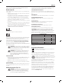
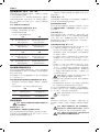
DWS780
Voltage V
AC
220
Type 10
Power input W 1675
Blade diameter mm 305
Blade bore mm 30
Blade body thickness mm 1.8
Max. blade speed min
-1
1900-3800
Max. cross-cut capacity 90° mm 349
Max. mitre capacity 45° mm 244
Max. depth of cut 90° mm 112
Max. depth of bevel cross-cut 45° mm 56
Mitre (max. positions) left 50°
right 60°
Bevel (max. positions) left 49°
right 49°
0° mitre
Resulting width at max. height 112 mm mm 299
Resulting width at max. height 110 mm mm 303
Resulting height at max. width 345 mm mm 76
45° mitre left
Resulting width at max. height 112 mm mm 200
Resulting height at max. width 244 mm mm 76
45° mitre right
Resulting width at max. height 112 mm mm 211
Resulting height at max. width 244 mm mm 76
45° bevel left
Resulting width at max. height 63 mm mm 268
Resulting height at max. width 345 mm mm 44
45° bevel right
Resulting width at max. height 62 mm mm 193
Resulting height at max. width 345 mm mm 28
Automatic blade brake time s < 10
Weight kg 25.4
L
PA
(sound pressure) dB(A) 93
K
PA
(sound pressure uncertainty) dB(A) 3.0
L
WA
(sound power) dB(A) 100
K
WA
(sound power uncertainty) dB(A) 3.0
Vibration total values (triax vector sum) determined according to EN 61029:
Vibration emission value a
h
a
h
= m/s
2
< 2.5
Uncertainty K = m/s
2
1.5
MITRE SAW
DWS780
Congratulations!
You have chosen a DeWALT tool. Years of experience, thorough
product development and innovation make DeWALT one of the most
reliable partners for professional power tool users.
Technical Data
An estimation of the level of exposure to vibration should
also take into account the times when the tool is switched
off or when it is running but not actually doing the job.
This may significantly reduce the exposure level over the
total working period.
Identify additional safety measures to protect the operator
from the effects of vibration such as: maintain the tool and
the accessories, keep the hands warm, organisation of
work patterns.
Definitions: Safety Guidelines
The definitions below describe the level of severity for each signal
word. Please read the manual and pay attention to these symbols.
DANGER: Indicates an imminently hazardous situation
which, if not avoided, will result in death or serious
injury.
WARNING: Indicates a potentially hazardous situation
which, if not avoided, could result in death or serious
injury.
CAUTION: Indicates a potentially hazardous situation
which, if not avoided, may result in minor or moderate
injury.
NOTICE: Indicates a practice not related to personal
injury which, if not avoided, may result in property
damage.
Denotes risk of electric shock.
Denotes risk of fire.
Safety Instructions
WARNING! When using electric tools basic safety
precautions should always be followed to reduce the risk
of fire, electric shock and personal injury including the
following.
Read all these instructions before attempting to operate this product
and save these instructions.
SAVE THIS MANUAL FOR FUTURE REFERENCE
General Safety Rules
1. Keep work area clear.
Cluttered areas and benches invite injuries.
2. Consider work area environment.
Do not expose the tool to rain. Do not use the tool in damp or
wet conditions. Keep the work area well lit (250–300 Lux). Do
not use the tool where there is a risk of causing fire or explosion,
e.g., in the presence of flammable liquids and gases.
3. Guard against electric shock.
Avoid body contact with earthed surfaces (e.g., pipes, radiators,
cookers and refrigerators). When using the tool under extreme
conditions (e.g., high humidity, when metal swarf is being
produced, etc.), electric safety can be improved by inserting an
isolating transformer or a (FI) earth-leakage circuit-breaker.
4. Keep other persons away.
Do not let persons, especially children, not involved in the work,
touch the tool or the extension cord and keep them away from
the work area.
5. Store idle tools.
When not in use, tools must be stored in a dry place and locked
up securely, out of reach of children.
6. Do not force the tool.
It will do the job better and safer at the rate to which it was
intended.
The vibration emission level given in this information sheet has been
measured in accordance with a standardised test given in EN 61029
and may be used to compare one tool with another. It may be used for
a preliminary assessment of exposure.
WARNING: IThe declared vibration emission level
represents the main applications of the tool. However if
the tool is used for different applications, with different
accessories or poorly maintained, the vibration emission
may differ. This may significantly increase the exposure
level over the total working period.
ENGLISH
10

ENGLISH
Additional Safety Rules for Mitre Saws
• Themachineisprovidedwithaspecialconguredpowersupply
cord which can only be replaced by the manufacturer or its
authorised service agent.
• Donotusethesawtocutothermaterialsthanthose
recommended by the manufacturer.
• Donotoperatethemachinewithoutguardsinposition,orif
guards do not function or are not maintained properly.
• Ensurethatthearmissecurelyxedwhenperformingbevelcuts.
• Keeptheoorareaaroundthemachinelevel,well-maintainedand
free of loose materials, e.g., chips and cut-offs.
• Usecorrectlysharpenedsawblades.Observethemaximum
speed mark on the saw blade.
• Makesurealllockingknobsandclamphandlesaretightbefore
starting any operation.
• Neverplaceeitherhandinthebladeareawhenthesawis
connected to the electrical power source.
• Neverattempttostopamachineinmotionrapidlybyjamminga
tool or other means against the blade; serious accidents can occur.
• Beforeusinganyaccessoryconsulttheinstructionmanual.The
improper use of an accessory can cause damage.
• Useaholderorweargloveswhenhandlingasawblade.
• Ensurethatthesawbladeismountedcorrectlybeforeuse.
• Makesurethatthebladerotatesinthecorrectdirection.
• Donotusebladesoflargerorsmallerdiameterthan
recommended. For the proper blade rating refer to the technical
data.Useonlythebladesspeciedinthismanual,complyingwith
EN847-1.
• Doconsiderapplyingspeciallydesignednoise-reductionblades.
• DonotuseHSSblades.
• Donotusecrackedordamagedsawblades.
• Donotuseanyabrasiveordiamonddiscs.
• Neveruseyoursawwithoutthekerfplate.
• Raisethebladefromthekerfintheworkpiecepriortoreleasingthe
switch.
• Donotwedgeanythingagainstthefantoholdthemotorshaft.
• Thebladeguardonyoursawwillautomaticallyraisewhenthe
head up-lock release lever is pushed and the arm is brought
down; it will lower over the blade as the arm is raised.
• Neverraisethebladeguardmanuallyunlessthesawisswitched
off. The guard can be raised by hand when installing or removing
saw blades or for inspection of the saw.
• Checkperiodicallythatthemotorairslotsarecleanandfreeof
chips.
• Replacethekerfplatewhenworn.Refertoservicepartslist
included.
• Disconnectthemachinefromthemainsbeforecarryingoutany
maintenance work or when changing the blade.
• Neverperformanycleaningormaintenanceworkwhenthe
machine is still running and the head is not in the upper position.
• IfyouuseanLEDtoindicatethecuttingline,makesurethatthe
LEDisofclass2accordingtoEN62471.DonotreplaceanLED
diodewithadifferenttype.Ifdamaged,havetheLEDrepairedby
an authorised repair agent.
• Thefrontsectionoftheguardislouveredforvisibilitywhilecutting.
Although the louvers dramatically reduce flying debris, they are
openings in the guard and safety glasses should be worn at all
times when viewing through the louvers.
• Connectthesawtoadustcollectiondevicewhensawingwood.
Always consider factors which influence exposure of dust such as:
– type of material to be machined (chip board produces more
dust than wood);
– sharpness of the saw blade;
– correct adjustment of the saw blade;
– dust extractor with air velocity not less than 20m/s.
Ensurethatthelocalextractionaswellashoods,bafesand
chutes are properly adjusted.
7.Use the right tool.
Do not force small tools to do the job of a heavy duty tool. Do
not use tools for purposes not intended; for example do not use
circular saws to cut tree limbs or logs.
8.Dress properly.
Do not wear loose clothing or jewellery, as these can be caught
inmovingparts.Non-skidfootwearisrecommendedwhen
working outdoors. Wear protective hair covering to contain long
hair.
9. Use protective equipment.
Alwaysusesafetyglasses.Useafaceordustmaskifworking
operations create dust or flying particles. If these particles might
be considerably hot, also wear a heat-resistant apron. Wear ear
protection at all times. Wear a safety helmet at all times.
10. Connect dust extraction equipment.
If devices are provided for the connection of dust extraction and
collecting equipment, ensure these are connected and properly
used.
11. Do not abuse the cord.
Never yank the cord to disconnect it from the socket. Keep
thecordawayfromheat,oilandsharpedges.Nevercarrythe
tool by its cord.
12. Secure work.
Where possible use clamps or a vice to hold the work. It is safer
than using your hand and it frees both hands to operate the tool.
13. Do not overreach.
Keep proper footing and balance at all times.
14. Maintain tools with care.
Keep cutting tools sharp and clean for better and safer
performance. Follow instructions for lubricating and changing
accessories. Inspect tools periodically and if damaged have
them repaired by an authorized service facility. Keep handles and
switches dry, clean and free from oil and grease.
15. Disconnect tools.
When not in use, before servicing and when changing
accessories such as blades, bits and cutters, disconnect tools
from the power supply.
16. Remove adjusting keys and wrenches.
Form the habit of checking to see that adjusting keys and
wrenches are removed from the tool before operating the tool.
17.Avoid unintentional starting.
Donotcarrythetoolwithangerontheswitch.Besurethatthe
tool is in the “off” position before plugging in.
18.Use outdoor extension leads.
Beforeuse,inspecttheextensioncableandreplaceifdamaged.
When the tool is used outdoors, use only extension cords
intended for outdoor use and marked accordingly.
19. Stay alert.
Watchwhatyouaredoing.Usecommonsense.Donotoperate
the tool when you are tired or under the influence of drugs or
alcohol.
20. Check for damaged parts.
Beforeuse,carefullycheckthetoolandmainscabletodetermine
that it will operate properly and perform its intended function.
Check for alignment of moving parts, binding of moving parts,
breakage of parts, mounting and any other conditions that may
affect its operation. A guard or other part that is damaged should
be properly repaired or replaced by an authorized service centre
unless otherwise indicated in this instruction manual. Have
defective switches replaced by an authorized service centre. Do
notusethetooliftheswitchdoesnotturnitonandoff.Never
attempt any repairs yourself.
WARNING! The use of any accessory or attachment or
performance of any operation with this tool other than
those recommended in this instruction manual may
present a risk of personal injury.
21. Have your tool repaired by a qualified person.
This electric tool complies relevant safety rules. Repairs should
only be carried out by qualified persons using original spare parts;
otherwise this may result in considerable danger to the user.
11

ENGLISH
Wear eye protection.
Carrying point.
Keep hands away from blade.
Do not stare directly into the light source.
Hazardous optical radiation.
DATE CODE POSITION (FIG. 1A)
The date code (i), which also includes the year of manufacture, is
printed into the housing.
Example:
2011 XX XX
Year of Manufacture
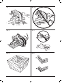
Package Contents
The package contains:
1 Assembled mitre saw
1 Blade wrench
1 Saw blade
1 Dustbag
1 Material clamp
1 Instruction manual
1 Exploded drawing
• Checkfordamagetothetool,partsoraccessorieswhichmayhave
occurred during transport.
• Takethetimetothoroughlyreadandunderstandthismanualprior
to operation.
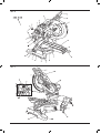
Description (fig. 1A–8)
WARNING:Nevermodifythepowertooloranypartofit.
Damage or personal injury could result.
Fig. 1A
a. Lower guard
b. Head up-lock release lever
c. Operating handle
d. Carrying handle
e. Motor housing
f. Motor endcap
g. Rail lock knob
h. Rail set screw adjustment
i. Date code
j. Rails
k. Bevel scale
l. Lock down pin
m. Fence adjustment knob
n. Fence
o. Base fence
p. Hand indentation
q. Table
r. Bench mounting holes
s. Mitre scale
t. Dust duct inlet
u. Mitre lock handle
v. Mitre latch button
w. Kerf plate
• Pleasebeawareofthefollowingfactorsinuencingexposureto
noise:
– use saw blades designed to reduce the emitted noise;
– use only well sharpened saw blades.
• Machinemaintenanceshallbeconductedperiodically.
• Provideadequategeneralorlocalizedlighting.
• Ensurethatanyspacersandspindleringsaresuitableforthe
purpose as stated in this manual.
• Refrainfromremovinganycut-offsorotherpartsoftheworkpiece
from the cutting area while the machine is running and the saw head
is not in the upper position.
• Nevercutworkpiecesshorterthan200mm.
• Withoutadditionalsupportthemachineisdesignedtoacceptthe
maximum workpiece size for cross-cutting:
– Maximumheight:112mm
– Maximumwidth:345mm
– Maximumlength:600mm
– Longer workpiece needs to be supported by suitable additional
support,e.g.DE7080-XJsupportorDE7023-XJorDE7033-XJ
legstand. Always clamp the workpiece safely.
• Incaseofanaccidentormachinefailure,immediatelyturnthe
machine off and disconnect machine from the power source.
• Reportthefailureandmarkthemachineinsuitableformtoprevent
other people from using the defective machine.
• Whenthesawbladeisblockedduetoabnormalfeedforceduring
cutting, turn the machine off and disconnect it from power supply.
Remove the workpiece and ensure that the saw blade runs free.
Turn the machine on and start new cutting operation with reduced
feed force.
• Nevercutlightalloy,especiallymagnesium.
• Wheneverthesituationallows,mountthemachinetoabenchusing
boltswithadiameterof8mmand80mminlength.
• Ensuretheoperatorisadequatelytrainedintheuse,adjustmentand
operation of the machine.
• Beforeworkingselectthecorrectsawbladeforthematerialtobe
cut.
• Useonlysawbladeswherethespeedmarkedonthesawbladeis
at least equal to the speed marked on the rating blade.
• Ensurebeforeeachcutthatthemachineislocatedonanevenand
stable surface to prevent movement.
Residual Risks
The following risks are inherent to the use of saws:
– Injuries caused by touching the rotating parts.
In spite of the application of the relevant safety regulations and the
implementation of safety devices, certain residual risks cannot be
avoided. These are:
– Impairment of hearing.
– Risk of accidents caused by the uncovered parts of the rotating saw
blade.
– Risk of injury when changing the blade.
– Risk of squeezing fingers when opening the guards.
– Health hazards caused by breathing dust developed when sawing
wood,especiallyoak,beechandMDF.
The following factors increase the risk of breathing problems:
– Nodustextractorconnectedwhensawingwood.
– Insufficient dust extraction caused by uncleaned exhaust filters.
Markings on Tool
The following pictograms are shown on the tool:
Read instruction manual before use.
Wear ear protection.
12

ENGLISH
ASSEMBLY AND ADJUSTMENTS
WARNING: To reduce the risk of injury, turn unit off
and disconnect machine from power source before
installing and removing accessories, before adjusting
or changing set-ups or when making repairs. Besure
thetriggerswitchisintheOFFposition.Anaccidental
start-up can cause injury.
Unpacking (fig. 1A, 9)
1. Open the box and lift the saw out by the convenient carrying handle
(d), as shown in figure 9.
2. Place the saw on a smooth, flat surface.
3. Release the rail lock knob (g), and push the saw head back to lock
it in the rear position.
4. Press down lightly on the operating handle (c) and pull out the lock
down pin (l).
5. Gently release the downward pressure and hold the operating
handle, allowing it to rise to its full height.
Bench Mounting (fig. 1A)
Holes (r) are provided in all four feet to facilitate bench mounting. Two
different-sized holes are provided to accommodate different sizes of
screws. Use either hole; it is not necessary to use both.
Always mount your saw firmly to a stable surface to prevent movement.
To enhance the tool’s portability, it can be mounted to a piece of 12.7
mm (1/2”) or thicker plywood which can then be clamped to your work
support or moved to other job sites and reclamped.
NOTE: If you elect to mount your saw to a piece of plywood, make sure
that the mounting screws don’t protrude from the bottom of the wood.
The plywood must sit flush on the work support. When clamping the
saw to any work surface, clamp only on the clamping bosses where
the mounting screw holes are located. Clamping at any other point will
interfere with the proper operation of the saw.
CAUTION: To prevent binding and inaccuracy, be sure
the mounting surface is not warped or otherwise uneven. If
the saw rocks on the surface, place a thin piece of material
under one saw foot until the saw sits firmly on the mounting
surface.
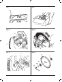
Changing or Installing a New Saw Blade
REMOVING THE BLADE (FIG. 10A–10D)
WARNING: To reduce the risk of injury, turn unit off
and disconnect machine from power source before
installing and removing accessories, before adjusting
or changing set-ups or when making repairs. Besure
thetriggerswitchisintheOFFposition.Anaccidentalstart-
up can cause injury.
•Neverdepressthespindlelockbuttonwhilethebladeis
under power or coasting.
•Donotcutlightalloyandferrousmetal(containingironor
steel) or masonry or fibre cement product with this mitre saw.
•Depresstheheadup-lockreleaselever(b)torelease
the lower guard (a), then raise the lower guard as far as
possible.
1. Unplug the saw.
2. Raise the arm to the upper position and raise the lower guard (a) as
far as possible.
3. Depress the spindle lock button (qq) while carefully rotating the saw
blade by hand until the lock engages.
4. Keeping the button depressed, use the other hand and the wrench
provided (cc) to loosen the blade screw. (Turn clockwise, left-hand
threads.)
5. Remove the blade screw (pp), outer clamp washer (rr) and blade
(ss). The inner clamp washer (tt) may be left on the spindle.
INSTALLING A BLADE (FIG. 10A–10D)
1. Unplug the saw.
2. With the arm raised and the lower guard held open, place the blade
on the spindle, and seat it on the inner blade clamp with the teeth
at the bottom of the blade pointing toward the back of the saw.
Fig. 1B
x. Trigger switch
y. XPS
TM
on/off switch
z. Wing nut
aa. Depth adjustment screw
bb. Grooving stop
cc. Blade wrench
dd. Base
ee. Bevel lock knob
ff. 0° bevel stop
gg. Belt cover
hh. Electronic speed control dial
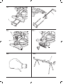
Optional accessories
Fig. 2
ii. DE7080-XJ Extension work support
Fig. 3
jj. DE7051-XJ Adjustable length stop
Fig. 4
kk. DE7082-XJ Workpiece clamp
Fig. 5
ll. DE7084-XJ Crown molding fence
Fig. 6
mm. DE7053-XJ Dustbag
Fig. 7
nn. DE7023-XJ / DE7033-XJ Leg stand
Fig. 8
oo. DE7025-XJ Clamp brackets
INTENDED USE
Your DeWALT DWS780 Mitre Saw has been designed for professional
cutting of wood, wood products and plastics. It performs the sawing
operations of cross-cutting, bevelling and mitring easily, accurately and
safely.
This unit is designed for use with a nominal blade diameter 305 mm
carbide tip blade.
DO NOT use under wet conditions or in the presence of flammable
liquids or gases.
These mitre saws are professional power tools.
DO NOT let children come into contact with the tool. Supervision is
required when inexperienced operators use this tool.
WARNING! Do not use the machine for purposes other
than intended.
Electrical Safety
The electric motor has been designed for one voltage only. Always
check that the power supply corresponds to the voltage on the rating
plate.
Your DeWALT tool is double insulated in accordance with
EN 61029; therefore no earth wire is required.
If the supply cord is damaged, it must be replaced by a specially
prepared cord available through the DeWALT service organisation.
Using an Extension Cable
If an extension cable is required, use an approved 3–core extension
cable suitable for the power input of this tool (see Technical Data). The
minimum conductor size is 1.5 mm
2
; the maximum length is 30 m.
When using a cable reel, always unwind the cable completely.
13

ENGLISH
RAIL LOCK KNOB (FIG. 1A)
The rail lock knob (g) allows you to lock the saw head firmly to keep it
from sliding on the rails (j). This is necessary when making certain cuts or
when transporting the saw.
DEPTH STOP (FIG. 1B)
The depth stop (bb) allows the depth of cut of the blade to be limited.
The stop is useful for applications such as grooving and tall vertical cuts.
Rotate the depth stop forward and adjust the depth adjustment screw
(aa) to set the desired depth of cut. To secure the adjustment, tighten the
wing nut (z). Rotating the depth stop to the rear of the saw will bypass
the depth stop feature. If the depth adjustment screw is too tight to
loosen by hand, the provided blade wrench (cc) can be used to loosen
the screw.
LOCK DOWN PIN (FIG. 1A)
WARNING:ThelockdownpinshouldbeusedONLYwhen
carryingorstoringthesaw.NEVERusethelockdownpin
for any cutting operation.
To lock the saw head in the down position, push the saw head down,
push the lock down pin (l) in and release the saw head. This will hold
the saw head safely down for moving the saw from place to place. To
release, press the saw head down and pull the pin out.
SLIDE LOCK LEVER (FIG. 13, 23)
The slide lock lever (a6) places the saw in a position to maximize cutting
of base molding when cut vertically as shown in figure 23.
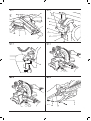
Adjustment
Your mitre saw is fully and accurately adjusted at the factory at the time
of manufacture. If readjustment due to shipping and handling or any
other reason is required, follow the instructions below to adjust your saw.
Once made, these adjustments should remain accurate.
MITRE SCALE ADJUSTMENT (FIG. 11, 14)
1. Unlock the mitre lock handle (u) and swing the mitre arm until the
mitre latch button (v) locks it at the 0° mitre position. Do not lock
the mitre lock handle.
2. Place a square against the saw’s fence and blade, as shown. (Do
not touch the tips of the blade teeth with the square. To do so will
cause an inaccurate measurement.)
3. If the saw blade is not exactly perpendicular to the fence, loosen
the four screws (ww) that hold the mitre scale (s) and move the
mitre lock handle and the scale left or right until the blade is
perpendicular to the fence, as measured with the square.
4. Retighten the four screws. Pay no attention to the reading of the
mitre pointer (uu) at this time.
MITRE POINTER ADJUSTMENT (FIG. 11)
1. Unlock the mitre lock handle (u) to move the mitre arm to the zero
position.
2. With the mitre lock handle unlocked, allow the mitre latch to snap
into place as you rotate the mitre arm to zero.
3. Observe the mitre pointer (uu) and mitre scale (s) shown in figure 11.
If the pointer does not indicate exactly zero, loosen the mitre pointer
screw (v v) holding the pointer in place, reposition the pointer and
tighten the screw.
BEVEL SQUARE TO TABLE ADJUSTMENT (FIG. 1A, 1B, 12, 15)
1. To align the blade square to the table, lock the arm in the down
position with the lock down pin (l).
2. Place a square against the blade, ensuring the square is not on top
of a tooth.
3. Loosen the bevel lock knob (ee) and ensure the arm is firmly
against the 0° bevel stop.
4. Rotate the 0° bevel adjustment screw (a5) with the 13 mm (1/2”)
blade wrench (cc) as necessary so that the blade is at 0° bevel to
the table.
BEVEL POINTER ADJUSTMENT (FIG. 12)
If the bevel pointers (yy) do not indicate zero, loosen each screw (xx) that
holds each bevel pointer in place and move them as necessary. Ensure
the 0° bevel is correct and the bevel pointers are set before adjusting any
other bevel angle screws.
3. Assemble the outer clamp washer onto the spindle.
4. Install the blade screw and, engaging the spindle lock, tighten the
screw firmly with wrench provided (turn counterclockwise, left-hand
threads).
WARNING!Beawarethesawbladeshallbereplacedin
thedescribedwayonly.Onlyusesawbladesasspecied
under Technical Data; Cat. no.: DT4260 is suggested.
Transporting the Saw (fig. 1A, 1B)
WARNING: To reduce the risk of serious personal
injury, ALWAYS lock the rail lock knob, mitre lock handle,
bevel lock handle, lock down pin and fence adjustment
knobs before transporting saw.
In order to conveniently carry the mitre saw, a carrying handle (d) has
been included on the top of the saw arm.
• Totransportthesaw,lowertheheadanddepressthelockdown
pin (l).
• Locktheraillockknobwiththesawheadinthefrontposition,lock
the mitre arm in the full left mitre angle, slide the fence (n) completely
inward and lock the bevel lock knob (ee) with the saw head in the
vertical position to make the tool as compact as possible.
• Alwaysusethecarryinghandle(d)orthehandindentations(p).
Features and Controls
WARNING: To reduce the risk of serious personal
injury, turn off the tool and disconnect it from the
power source before attempting to move it, change
accessories or make any adjustments.
MITRE CONTROL (FIG. 11)
The mitre lock handle (u) and mitre latch button (v) allow you to mitre
your saw to 60° right and 50° left. To mitre the saw, lift the mitre lock
handle, push the mitre latch button and set the mitre angle desired on
the mitre scale (s). Push down on the mitre lock handle to lock the mitre
angle.
BEVEL LOCK KNOB (FIG. 1B)
The bevel lock allows you to bevel the saw 49° left or right. To adjust the
bevel setting, turn the knob (ee) counterclockwise. The saw head bevels
easily to the left or to the right once the 0° bevel override knob is pulled.
To tighten, turn the bevel lock knob clockwise.
0° BEVEL OVERRIDE (FIG. 1B)
The bevel stop override (ff) allows you to bevel the saw to the right past
the 0° mark.
When engaged, the saw will automatically stop at 0° when brought up
from the left. To temporarily move past 0° to the right, pull the bevel lock
knob (ee). Once the knob is released, the override will be reengaged. The
bevel lock knob can be locked out by twisting the knob 180°.
When at 0°, the override locks in place. To operate the override, bevel
the saw slightly to the left.
45° BEVEL STOP OVERRIDE (FIG. 12)
There are two bevel stop override levers, one on each side of the saw.
To bevel the saw, left or right, past 45°, push the 45° bevel override lever
(a1) rearward. When in the rearward position, the saw can bevel past
these stops. When the 45° stops are needed, pull the 45° bevel override
lever forward.
CROWN BEVEL PAWLS (FIG. 12)
When cutting crown molding laying flat, your saw is equipped
to accurately and rapidly set a crown stop, left or right (refer to
Instructions for Cutting Crown Molding Laying Flat and Using the
Compound Features). The crown bevel pawl (a3) can be rotated to
contact the crown adjustment screw.
To reverse the crown bevel pawl, remove the retaining screw, the 22.5°
bevel pawl (a2) and the 30° crown bevel pawl (a3). Flip the crown bevel
pawl (a3) so the 33.86° text is facing up. Reattach the screw to secure
the 22.5° bevel pawl and the crown bevel pawl. The accuracy setting will
not be affected.
22.5° BEVEL PAWLS (FIG. 12)
Your saw is equipped to rapidly and accurately set a 22.5° bevel, left
or right. The 22.5° bevel pawl (a2) can be rotated to contact the crown
adjustment screw (zz).
14

ENGLISH
MITRE LOCK ADJUSTMENT (FIG. 1A, 16)
The mitre lock rod (a7) should be adjusted if the table of the saw can be
moved when the mitre lock handle is locked (down).
1. Put the mitre lock handle (u) in the unlocked (up) position.
2. Using a 13 mm (1/2”) open end wrench, loosen the lock nut (a8) on
the mitre lock rod.
3. Using a slotted screwdriver, tighten the mitre lock rod by turning it
clockwise as shown in figure 16. Turn the lock rod until it is snug,
then turn counterclockwise one turn.
4. Re-lock the mitre lock to a non-detented measurement on the mitre
scale – for example, 34° – and make sure the table will not rotate.
5. Tighten lock nut.
Prior to Operation
• Installtheappropriatesawblade.Donotuseexcessivelyworn
blades. The maximum rotation speed of the tool must not exceed
that of the saw blade. Do not use any abrasive blades.
• Donotattempttocutexcessivelysmallpieces.
• Allowthebladetocutfreely.Donotforce.
• Allowthemotortoreachfullspeedbeforecutting.
• Makesurealllockingknobsandclamphandlesaretight.
• Securetheworkpiece.
• Althoughthissawwillcutwoodandmanynonferrousmaterials,
these operating instructions refer to the cutting of wood only. The
same guidelines apply to the other materials. Do not cut ferrous (iron
and steel) materials, fibre cement or masonry with this saw!
• Makesuretousethekerfplate.Donotoperatethemachineifthe
kerf slot is wider than 10 mm.
OPERATION
Instructions for Use
WARNING: Always observe the safety instructions and
applicable regulations.
WARNING: To reduce the risk of serious personal
injury, turn off the tool and disconnect it from the
power source before attempting to move it, change
accessories or make any adjustments.
Refer to Saw Blades under Optional Accessories to select the blade
that best fits your needs.
Ensure the machine is placed to satisfy your ergonomic conditions in
terms of table height and stability. The machine site shall be chosen so
that the operator has a good overview and enough free surrounding
space around the machine that allows handling of the workpiece
without any restrictions.
To reduce effects of vibration make sure the environment temperature is
not too cold, the machine and accessories are well maintained and the
workpiece size is suitable for this machine.
TheattentionofUKusersisdrawntothe“woodworkingmachines
regulations1974”andanysubsequentamendments.
Plug the saw into any household 60 Hz power source. Refer to the
nameplate for voltage. Be sure the cord will not interfere with your work.
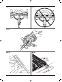
Proper Body and Hand Position (fig. 17A, 17B)
WARNING: To reduce the risk of serious personal injury,
ALWAYSuseproperhandpositionasshowning.17A.
WARNING: To reduce the risk of serious personal injury,
ALWAYS hold securely in anticipation of a sudden reaction.
• Neverplacehandsnearcuttingarea.Placehandsnocloserthan
152 mm (6”) from the blade.
• Holdtheworkpiecetightlytothetableandthefencewhencutting.
Keep hands in position until the trigger has been released and the
blade has completely stopped.
BEVEL STOP 45º RIGHT AND LEFT ADJUSTMENT (FIG. 1B, 12)
To adjust the right 45° bevel stop:
1. Loosen the bevel lock knob (ee) and pull the 0° bevel stop (ff) to
override the 0° bevel stop.
2. When the saw is fully to the right, if the bevel pointer (yy) does not
indicate exactly 45°, turn the left 45° bevel adjustment screw (a4)
with the 13 mm (1/2”) blade wrench (cc) until the bevel pointer
indicates 45°.
To adjust the left 45° bevel stop:
1. Loosen the bevel lock knob and tilt the head to the left.
2. If the bevel pointer does not indicate exactly 45°, turn the right 45°
bevel adjustment screw until the bevel pointer reads 45°.
ADJUSTING THE BEVEL STOP TO 22.5° (OR 30°) (FIG. 1B, 12)
NOTE: Adjust the bevel angles only after performing the 0° bevel angle
and bevel pointer adjustment.
To set the left 22.5° bevel angle, flip out the left 22.5° bevel pawl (a2).
Loosen the bevel lock knob (ee) and tilt the head fully to the left. If
the bevel pointer (yy) does not indicate exactly 22.5°, turn the crown
adjustment screw (zz) contacting the pawl with a 10 mm (7/16”) wrench
until the bevel pointer reads 22.5°.
To adjust the right 22.5° bevel angle, flip out the right 22.5° bevel pawl.
Loosen the bevel lock knob and pull the 0° bevel stop (ff) to override the
0° bevel stop. When the saw is fully to the right, if the bevel pointer does
not indicate exactly 22.5°, turn the crown adjustment screw contacting
the pawl with a 10 mm (7/16”) wrench until the bevel pointer indicates
exactly 22.5°.
FENCE ADJUSTMENT (FIG. 1A)
The upper part of the fence can be adjusted to provide clearance,
allowing the saw to bevel to a full 49° both left and right.
1. To adjust each fence (n), loosen the fence adjustment knob (m) and
slide the fence outward.
2. Make a dry run with the saw turned off and check for clearance.
3. Adjust the fence to be as close to the blade as practical to provide
maximum workpiece support, without interfering with arm up and
down movement.
4. Tighten the fence adjustment knob securely.
5. When the bevel operations are complete, relocate the fence.
For certain cuts, it may be desirable to bring the fences closer to the
blade. To do so, back the fence adjustment knobs (m) out two turns
and move the fences closer to the blade past the normal limit, then
tighten the fence adjustment knobs. Make a dry cut first to ensure the
blade does not contact the fences.
NOTE: The tracks of the fences can become clogged with sawdust.
Use a brush or some low pressure air to clear the guide grooves.
GUARD ACTUATION AND VISIBILITY (FIG. 1A)
The lower guard (a) on your saw has been designed to automatically
uncover the blade when the arm is brought down and to cover the
blade when the arm is raised.
The guard can be raised by hand when installing or removing saw
blades or for inspection of the saw. NEVER RAISE THE LOWER
GUARD MANUALLY UN LESS THE BLADE IS STOPPED.
KERF PLATE ADJUSTMENT (FIG. 1A)
To adjust the kerf plates (w), loosen the screws holding the kerf plates
in place. Adjust so that the kerf plates are as close as possible without
interfering with the blade’s movement.
If a zero kerf width is desired, adjust the kerf plates as close to each
other as possible. They can now be cut slowly with the saw blade to
give the smallest gap possible between the blade and the kerf plates.
RAIL GUIDE ADJUSTMENT (FIG. 1A)
Regularly check the rails (j) for play or clearance.
The right rail can be adjusted with the set screw (h). To reduce
clearance, use a 4 mm hex wrench and rotate the set screw clockwise
gradually while sliding the saw head back and forth.
15

ENGLISH
MITRE CROSSCUT
The mitre angle angle is often 45° for making corners, but can be set
anywhere from zero to 50° left or 60° right. Proceed as for a straight
vertical crosscut.
When performing a mitre cut on workpieces wider than 51 x 105 mm
(2” x 4”) that are shorter in length, always place the longer side against
the fence (fig. 19).
BEVEL CUT
Bevel angles can be set from 49° right to 49° left and can be cut with
the mitre arm set between 50° left or 60° right. Refer to the Features
and Controls section for detailed instructions on the bevel system.
1. Loosen the bevel lock (ee), and move the saw to the left or right as
desired. It is necessary to move the fence (n) to allow clearance.
Tighten the fence adjustment knob (m) after positioning the fences.
2. Tighten the bevel lock firmly.
At some extreme angles, the right or left side fence might have to be
removed. Refer to Fence Adjustment in the Adjustments section for
important information on adjusting the fences for certain bevel cuts.
To remove the left or right fence, unscrew the fence adjustment knob
(m) several turns and slide the fence out.
GROOVING (FIG. 1B)
Your saw is equipped with a grooving stop (bb), depth adjustment
screw (aa) and wing nut (z) to allow for groove cutting.
• Flipthegroovingstop(bb)towardsthefrontofthesaw.
• Adjustthewingnut(z)anddepthadjustmentscrew(aa)tosetthe
depth of the groove cut.
• Placeapieceofscrapmaterialofapprox.5cmbetweenfenceand
workpiece in order to perform a straight groove cut.
QUALITY OF CUT
The smoothness of any cut depends on a number of variables, such as
the material being cut, blade type, blade sharpness and rate of cut.
When smoothest cuts are desired for molding and other precision work,
a sharp (60 tooth carbide) blade and a slower, even cutting rate will
produce the desired results.
WARNING:Ensurethatthematerialdoesnotmoveor
creep while cutting; clamp it securely in place. Always let
the blade come to a full stop before raising arm. If small
fibers of wood still split out at the rear of the workpiece,
stick a piece of masking tape on the wood where the cut
willbemade.Sawthroughthetapeandcarefullyremove
tape when finished.
Clamping the Workpiece (fig. 4)
WARNING: A workpiece that is clamped, balanced
and secure before a cut may become unbalanced after
a cut is completed. An unbalanced load may tip the
saw or anything the saw is attached to, such as a table
or workbench. When making a cut that may become
unbalanced, properly support the workpiece and ensure
thesawisrmlyboltedtoastablesurface.Personalinjury
may occur.
WARNING: The clamp foot must remain clamped above
the base of the saw whenever the clamp is used. Always
clamp the workpiece to the base of the saw – not to any
otherpartoftheworkarea.Ensuretheclampfootisnot
clamped on the edge of the base of the saw.
CAUTION: Always use a work clamp to maintain control
and reduce the risk of workpiece damage and personal
injury, if your hands are required to be within 152 mm (6”)
of the blade during the cut.
Use the material clamp (kk) provided with your saw. Other aids such as
spring clamps, bar clamps or C-clamps may be appropriate for certain
sizes and shapes of material. The left or right fence will slide from side to
side to aid in clamping.
• ALWAYSMAKEDRYRUNS(UNPOWERED)BEFOREFINISH
CUTS SO THAT YOU CAN CHECK THE PATH OF THE BLADE.
DO NOT CROSS HANDS, AS SHOWN IN FIGURE 17B.
• Keepbothfeetrmlyontheoorandmaintainproperbalance.As
you move the mitre arm left and right, follow it and stand slightly to
the side of the saw blade.
• Sightthroughtheguardlouverswhenfollowingapencilline.
Switching On and Off (fig. 1B)
To turn the saw on, depress the trigger switch (x). To turn the tool off,
release the trigger switch.
Allow the blade to spin up to full operating speed before making the cut.
Release the trigger switch and allow the brake to stop the blade before
raising the saw head.
A hole is provided in the trigger switch for insertion of a padlock to lock
the saw off.
SETTING THE VARIABLE SPEED (FIG. 1B)
The speed control dial (hh) can be used for advance setting of the
required range of speed.
• Turnthespeedcontroldial(hh)tothedesiredrange,whichis
indicated by a number.
• Usehighspeedsforsawingsoftmaterialssuchaswood.Uselow
speeds for sawing metal.
Use of XPS
TM
LED Worklight System (fig. 1A, 1B)
NOTE: The mitre saw must be connected to a power source.
The XPS
TM
LED Worklight System is equipped with an on/off switch
(y). The XPS
TM
LED Worklight System is independent of the mitre saw’s
trigger switch. The light does not need to be on in order to operate the
saw.
To cut through an existing pencil line on a piece of wood:
1. Turn on the XPS
TM
system, then pull down on the operating handle
(c) to bring the saw blade close to the wood. The shadow of the
blade will appear on the wood.
2. Align the pencil line with the edge of the blade’s shadow. You may
have to adjust the mitre or bevel angles in order to match the pencil
line exactly.
Basic Saw Cuts (fig. 1A, 1B, 18, 19)
If the slide feature is not used, ensure the saw head is pushed back as
far as possible and the rail lock knob (g) is tightened. This will prevent
the saw from sliding along its rails as the workpiece is engaged.
Cutting of multiple pieces is not recommended but can be done safely
by ensuring that each piece is held firmly against the table and fence.
STRAIGHT VERTICAL CROSSCUT
1. Set and lock the mitre arm at zero, and hold the wood firmly on the
table (q) and against the fence (n).
2. With the rail lock knob (g) tightened, turn on the saw by squeezing
the trigger switch (x).
3. When the saw comes up to speed, lower the arm smoothly and
slowly to cut through the wood. Let the blade come to a full stop
before raising arm.
SLIDING CROSSCUT
When cutting anything larger than a 51 x 150 mm (2” x 6” [51 x 105 mm
(2” x 4”) at 45° mitre]) workpiece, use an out-down-back motion with
the rail lock knob (g) loosened (fig. 18).
Pull the saw out toward you, lower the saw head down toward the
workpiece, and slowly push the saw back to complete the cut.
Do not allow the saw to contact the top of the workpiece while pulling
out. The saw may run toward you, possibly causing personal injury or
damage to the workpiece.
16

ENGLISH
Cutting Compound Mitres (fig. 22)
A compound mitre is a cut made using a mitre angle and a bevel angle
at the same time. This is the type of cut used to make frames or boxes
with slanting sides like the one shown in figure 22.
WARNING: If the cutting angle varies from cut to cut,
check that the bevel lock knob and the mitre lock handle
are securely locked. These must be locked after making
any changes in bevel or mitre.
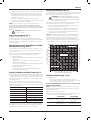
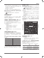
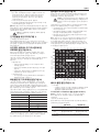
The chart (Table 1) shown below will assist you in selecting the proper
bevel and mitre settings for common compound mitre cuts.
• SelectthedesiredangleA(g.22)ofyourprojectandlocatethat
angle on the appropriate arc in the chart.
• Fromthatpointfollowthechartstraightdowntondthecorrect
bevel angle and straight across to find the correct mitre angle.
• Setyoursawtotheprescribedanglesandmakeafewtrialcuts.
Practise fitting the cut pieces together.
Example: To make a 4-sided box with 26° exterior angles (Angle A,
fig. 22), use the upper right arc. Find 26° on the arc scale. Follow the
horizontal intersecting line to either side to get mitre angle setting on
saw (42°). Likewise, follow the vertical intersecting line to the top or
bottom to get the bevel angle setting on the saw (18°). Always try cuts
on a few scrap pieces of wood to verify the settings on the saw.
Cutting Base Moulding (fig. 13, 23)
• Straight90°cuts:
– Position the wood against the fence and hold it in place as
shown in figure 23. Turn on the saw, allow the blade to reach full
speed and lower the arm smoothly through the cut.
CUTTING BASE MOULDING FROM 76 mm UP TO 171 mm (3” UP TO 6.75”) HIGH
VERTICALLY AGAINST THE FENCE
NOTE: Use the slide lock lever (a6), shown in figure 13, when cutting
base moulding measuring from 76 mm to 171 mm (3” to 6.75”) high
vertically against the fence.
Position material as shown in figure 23.
All cuts should be made with the back of the moulding against the fence
and with the bottom of the moulding against the table.
INSIDE CORNER OUTSIDE CORNER
Left side
Mitre left 45°
Save left side of cut
Mitre right 45°
Save left side of cut
Right side
Mitre right 45°
Save right side of cut
Mitre left 45°
Save right side of cut
Material up to 171 mm (6.75”) can be cut as described above.
TO INSTALL CLAMP
1. Insert it into the hole behind the fence. The clamp should be facing
toward the back of the mitre saw. The groove on the clamp rod
should be fully inserted into the base. Ensure this groove is fully
inserted into the base of the mitre saw. If the groove is visible, the
clamp will not be secure.
2. Rotate the clamp 180° toward the front of the mitre saw.
3. Loosen the knob to adjust the clamp up or down, then use the fine
adjust knob to firmly clamp the workpiece.
NOTE: Place the clamp on the opposite side of the base when
beveling. ALWAYS MAKE DRY RUNS (UNPOWERED) BEFORE
FINISH CUTS TO CHECK THE PATH OF THE BLADE. ENSURE THE
CLAMP DOES NOT INTERFERE WITH THE ACTION OF THE SAW OR
GUARDS.
WARNING: Always use a material clamp when cutting
non-ferrous metals.
Support for Long Pieces (fig. 7)
ALWAYS SUPPORT LONG PIECES.
For best results, use the DE7023-XJ or DE7033 leg stands (nn) to
extend the table width of your saw. Support long workpieces using any
convenient means such as sawhorses or similar devices to keep the
ends from dropping.
Cutting Picture Frames, Shadow Boxes And Other
Four-Sided Projects (fig. 20, 21)
Try a few simple projects using scrap wood until you develop a “feel”
for your saw. Your saw is the perfect tool for mitring corners like the one
shown in figure 20.
Sketch A in figure 21 shows a joint made with the bevel adjustment
method. The joint shown can be made using either method.
• Usingbeveladjustment:
– The bevel for the two boards is adjusted to 45° each, producing
a 90° corner.
– The mitre arm is locked in the zero position and the bevel
adjustment is locked at 45°.
– The wood is positioned with the broad flat side against the table
and the narrow edge against the fence.
• Usingmitreadjustment:
– The same cut can be made by mitring right and left with the
broad surface against the fence.
Cutting Trim Molding And Other Frames (fig. 21)
Sketch B in figure 21 shows a joint made by setting the mitre arm at 45°
to mitre the two boards to form a 90° corner. To make this type of joint,
set the bevel adjustment to zero and the mitre arm to 45°. Once again,
position the wood with the broad flat side on the table and the narrow
edge against the fence.
The two sketches in figure 21 are for four-sided objects only. As the
number of sides changes, so do the mitre and bevel angles. The chart
below gives the proper angles for a variety of shapes, assuming that all
sides are of equal length.
NUMBER OF SIDES MITRE OR BEVEL ANGLE
4 45°
5 36°
6 30°
7 25.7°
8 22.5°
9 20°
10 18°
For a shape that is not shown in the chart, use the following formula:
180º divided by the number of sides equals the mitre (if the material is
cut vertically) or bevel angle (if the material is cut laying flat).
17
SQUARE BOX
6 SIDED BOX
8 SIDED BOX
SET THIS MITER ANGLE ON SAW
ANGLE OF SIDE OF BOX (ANGLE “A”)
SET THIS BEVEL ANGLE ON SAW

ENGLISH
Use a stick wax cutting lubricant when cutting aluminum. Apply the
stick wax directly to the saw blade before cutting. Never apply stick wax
to a moving blade. The wax provides proper lubrication and keeps chips
from adhering to the blade.
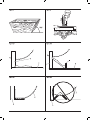
BOWED MATERIAL (FIG. 26A, 26B)
When cutting bowed material always position it as shown in figure
26A and never like that shown in figure 26B. Positioning the material
incorrectly will cause it to pinch the blade.
CUTTING PLASTIC PIPE OR OTHER ROUND MATERIAL
Plastic pipe can be easily cut with your saw. It should be cut just like
wood and clamped or held firmly to the fence to keep it from
rolling. This is extremely important when making angle cuts.
CUTTING LARGE MATERIAL (FIG. 27)
Occasionally you will encounter a piece of wood a little too large to fit
beneath the lower guard. If this occurs, place your right thumb on the
upper side of the guard (a) and roll the guard up just enough to clear the
workpiece, as shown in figure 27. Avoid doing this as much as possible,
but if need be, the saw will operate properly and make the bigger cut.
NEVER TIE, TAPE, OR OTHERWISE HOLD THE GUARD OPEN WHEN
OPERATING THIS SAW.
SPECIAL SET-UP FOR WIDE CROSSCUTS (FIG. 28A, 28B)
Your saw can cut very wide (up to 409 mm [16.1”]) workpieces when a
special set-up is used. To set the saw up for these workpieces, follow
these steps:
1. Remove both left and right sliding fences from the saw and set
aside. To remove them, unscrew the fence adjustment knobs (m)
several turns and slide each fence outward. Adjust and lock the
mitre control so that it is at 0° mitre.
2. Make a platform using a piece of 38 mm (1.5”) thick particleboard
or similar flat strong 38 mm thick wood to the dimensions: 368
x 660 mm (14.5” x 26”). The platform must be flat, otherwise the
material could move during cutting and cause injury.
3. Mount the 368 x 660 mm (14.5” x 26”) platform to the saw using
four 76.2 mm (3”) long wood screws through the holes (a9) in the
base fence (o) (fig. 28A). Four screws must be used to properly
secure the material. When the special set-up is used, the platform
will be cut into two pieces. Ensure the screws are tightened
properly, otherwise material could loosen and cause injury. Ensure
the platform is firmly flat on the table, against the fence, and
centred evenly from left to right.
WARNING:Ensurethesawismountedrmlytoastable
flat surface. Failure to do so could cause the saw to be
unstable and fall causing personal injury.
4. Place the workpiece to be cut on top of the platform mounted to
the table. Ensure the workpiece is firmly against the back of the
base fence (o) (fig. 28B).
5. Secure the material before cutting. Cut slowly through the material
using a out-down-and-back motion. Failure to clamp securely or
cut slowly could result in the material coming loose and causing
injury.
After several cuts are made at various mitre angles other than 0º, the
platform may weaken and not properly support the work. Install a new,
unused platform to the saw after presetting the desired mitre angle.
CAUTION: Continued use of a platform with several kerfs
may cause loss of material control and possible injury.
MAINTENANCE
Your DeWALT power tool has been designed to operate over a long
period of time with a minimum of maintenance. Continuous satisfactory
operation depends upon proper tool care and regular cleaning.
WARNING: To reduce the risk of injury, turn unit off
and disconnect machine from power source before
installing and removing accessories, before adjusting
or changing set-ups or when making repairs.Besure
thetriggerswitchisintheOFFposition.Anaccidental
start-up can cause injury.
WARNING: To reduce the risk of serious personal
injury, DO NOT touch the sharp points on the
blade with fingers or hands while performing any
maintenance.
Cutting Crown Moulding (fig. 1A, 24A, 24B)
Your mitre saw is well suited to the task of cutting crown moulding. In
order to fit properly, crown moulding must be compound mitred with
extreme accuracy.
Your mitre saw has special pre-set mitre latch points at 31.62° left and
right for cutting crown moulding at the proper angle and bevel stop
pawls at 33.86° left and right. There is also a mark on the bevel scale
(k) at 33.9°. The chart below gives the proper settings for cutting crown
moulding.
NOTE: Pretesting with scrap material is extremely important!
INSTRUCTIONS FOR CUTTING CROWN MOULDING LAYING FLAT AND USING THE
COMPOUND FEATURES (FIG. 24A)
1. Moulding should lay flat with the broad back surface down on the
saw table.
2. Place the top of the moulding against the fence.
3. The settings below are for 45° sprung crown moulding.
INSIDE CORNER OUTSIDE CORNER
Left
side
Bevel left 30°
Mitre table set at right 35.26°
Save left end of cut
Bevel right 30°
Mitre table set at left 35.26°
Save left end of cut
Right
side
Bevel right 30°
Mitre table set at left 35.26°
Save right end of cut
Bevel left 30°
Mitre table set at right 35.26°
Save right end of cut
4. The settings below are for crown moulding with 52° angles at the
top and 38° angles at the bottom.
INSIDE CORNER OUTSIDE CORNER
Left
side
Bevel left 33.9°
Mitre table set at right 31.62°
Save left end of cut
Bevel right 33.9°
Mitre table set at left 31.62°
Save left end of cut
Right
side
Bevel right 33.9°
Mitre table set at left 31.62°
Save right end of cut
Bevel left 33.9°
Mitre table set at right 31.62°
Save right end of cut
Alternative Method for Cutting Crown Moulding
Cutting crown moulding using this method does not require a bevel cut.
Minute changes in the mitre angle can be made without affecting the
bevel angle. When corners other than 90° are encountered, the saw can
be quickly and easily adjusted for them.
Use of the DW7084 crown moulding fence accessory (ll) is highly
recommended because of its degree of accuracy and convenience
(fig. 5).
INSTRUCTIONS FOR CUTTING CROWN MOULDING ANGLED BETWEEN THE
FENCE AND BASE OF THE SAW FOR ALL CUTS (FIG. 24B)
1. Angle the moulding so the bottom of the moulding (the part which
goes against the wall when installed) is against the fence and the
top of the moulding is resting on the saw table.
2. The angled “flats” on the back of the moulding must rest squarely
on the fence and saw table.
INSIDE CORNER OUTSIDE CORNER
Left
side
Mitre right at 45°
Save right side of cut
Mitre left at 45°
Save right side of cut
Right
side
Mitre left at 45°
Save left side of cut
Mitre right at 45°
Save left side of cut
Special Cuts
WARNING: Never make any cut unless the material is
secured on the table and against the fence.
ALUMINUM CUTTING (FIG. 25A, 25B)
ALWAYS USE THE APPROPRIATE SAW BLADE MADE
ESPECIALLY FOR CUTTING ALUMINUM.
Certain workpieces may require the use of a clamp or fixture to prevent
movement during the cut. Position the material so that you will be
cutting the thinnest cross section, as shown in figure 25A. Figure 25B
illustrates the wrong way to cut these extrusions.
18

ENGLISH
EXTENSION WORK SUPPORT: DE7080-XJ
The extension work support is used to support long workpieces. Your
saw base will accept two work supports (ii), one on each side.
ADJUSTABLE LENGTH STOP: DE7051-XJ
Requires the use of one work support (ii). The adjustable length stop
(jj) is used to make repetitive cuts of the same length from 0 to 107 cm
(42”).
CLAMP: DE7082-XJ
The clamp (kk) is used for firmly clamping workpiece to the saw table.
CROWN MOULDING FENCE: DE7084-XJ
The crown moulding fence (ll) is used for precision cutting of crown
moulding.
DUST BAG: DE7053-XJ
Equipped with a zipper for easy emptying, the dust bag (mm) will
capture the majority of the sawdust produced.
LEG STANDS: DE7023-XJ, DE7033-XJ
The leg stand (nn) is used to exend the table width of the saw.
CLAMP BRACKETS: DE7025-XJ
The clamp brackets (oo) are used for mounting the saw to a stand.
SAW BLADES: ALWAYS USE 305 mm (12”) SAW BLADES WITH
30 mm ARBOUR HOLES. SPEED RATING MUST BE AT LEAST
4800 RPM. Never use a smaller diameter blade. It will not be guarded
properly. Use crosscut blades only! Do not use blades designed for
ripping, combination blades or blades with hook angles in excess of 5°.
BLADE DESCRIPTIONS
APPLICATION DIAMETER TEETH
Construction Saw Blades (thin kerf with anti-stick rim)
General Purpose 305 mm (12”) 40
Fine Crosscuts 305 mm (12”) 60
Woodworking Saw Blades (provide smooth, clean cuts)
Fine crosscuts 305 mm (12”) 80
Non-ferrous metals 305 mm (12”) 96
Consult your dealer for further information on the appropriate
accessories.
Protecting the Environment
Separate collection. This product must not be disposed of
with normal household waste.
Should you find one day that your DeWALT product needs replacement,
or if it is of no further use to you, do not dispose of it with household
waste. Make this product available for separate collection.
Separate collection of used products and packaging allows
materials to be recycled and used again. Re-use of recycled
materials helps prevent environmental pollution and reduces
the demand for raw materials.
Local regulations may provide for separate collection of electrical
products from the household, at municipal waste sites or by the retailer
when you purchase a new product.
DeWALT provides a facility for the collection and recycling of DeWALT
products once they have reached the end of their working life. To take
advantage of this service please return your product to any authorised
repair agent who will collect them on our behalf.
You can check the location of your nearest authorised repair agent by
contacting your local DeWALT office at the address indicated in this
manual. Alternatively, a list of authorised DeWALT repair agents and
full details of our after-sales service and contacts are available on the
Internet at: www.2helpU.com.
DO NOT use lubricants or cleaners (particularly spray or aerosol) in the
vicinity of the plastic guard. The polycarbonate material used in the
guard is subject to attack by certain chemicals.
Brushes (fig. 1A)
Inspect carbon brushes regularly. Keep brushes clean and sliding freely
in their guides.
• Unplugtool,removethemotorendcap(f),liftthebrushspringand
withdraw the brush assembly.
• Ifthebrushesareworndowntoapproximately12.7mm(1/2”),the
springs will no longer exert pressure and they must be replaced.
• UseonlyidenticalDeWALT brushes. Use of the correct grade of
brush is essential for proper operation of electric brake. New brush
assemblies are available at DeWALT service centres.
• Alwaysreplacethebrushinspectioncapafterinspectionorservicing
the brushes.
• Thetoolshouldbeallowedto“runin”(runatnoload)for10minutes
before use to seat new brushes. The electric brake may be erratic in
operation until the brushes are properly seated (worn in).
• While“runningin”DONOTTIE,TAPE,OROTHERWISELOCKTHE
TRIGGER SWITCH ON. HOLD BY HAND ONLY.
Lubrication
Your power tool requires no additional lubrication.
Cleaning
Before use, carefully check the upper guard, lower guard and dust duct
to determine that they will operate properly. Ensure that chips, dust or
workpiece particles do not block of one of the functions.
In case of workpiece fragments jammed between the saw blade and
guards, disconnect the machine from the power supply and follow
the instructions given in Changing or Installing a New Saw Blade.
Remove the jammed parts and reassemble the saw blade.
Periodically clean all dust and wood chips from around AND UNDER the
base and the rotary table.
WARNING:Blowdirtanddustoutofthemainhousingwith
dry air as often as dirt is seen collecting in and around the
air vents. Wear approved eye protection and approved dust
mask when performing this procedure.
WARNING:Neverusesolventsorotherharshchemicals
for cleaning the non-metallic parts of the tool. These
chemicals may weaken the materials used in these parts.
Useaclothdampenedonlywithwaterandmildsoap.
Neverletanyliquidgetinsidethetool;neverimmerseany
part of the tool into a liquid.
WORKLIGHT CLEANING
• Carefullycleansawdustanddebrisfromworklightlenswithacotton
swab. Dust build-up can block the worklight and prevent it from
accurately indicating the line of cut.
• DONOTusesolventsofanykind;theymaydamagethelens.
• Withbladeremovedfromsaw,cleanpitchandbuild-upfromblade.
DUST DUCT CLEANING
With the saw unplugged and the saw head raised fully, low pressure air
or a large diameter dowel rod can be used to clear the dust out of the
dust duct.
Optional Accessories (fig. 2–8)
WARNING:Sinceaccessories,otherthanthoseoffered
by DeWALT, have not been tested with this product, use
of such accessories with this tool could be hazardous.
To reduce the risk of injury, only DeWALT recommended
accessories should be used with this product.
19

确 定 额 外 的 安 全 措 施 以 保 护 操 作 员 免 受 振 动 影 响 ,
比 如 : 保 养 工 具 和 配 件 、 保 持 双 手 温 暖 、 组 织 工 作
模式。
定义:安全准则
下列定义解释了各警示词的严重程度。请仔细阅读本手册并注意这
些标志。
危险:指示紧急的危险情况,如不加以避免,将导致死
亡或严重伤害。
警告:指示潜在的危险情况,如不加以避免,可能导致
死亡或严重伤害。
警示:指示潜在的危险情况,如不加以避免,可能导致
轻度或中度伤害。
注意:指示不涉及人身伤害的情况,如不加以避免,可
能导致财产损失。
指示有触电风险。
指示存在火灾风险。
安全须知
警告!使用电动工具时,请务必始终遵守下列基本安全
预防措施,降低火灾、触电和人身伤害风险。
使用本工具前,请仔细阅读本手册所有说明,并保管好本手册。
请保管好本手册,以备将来查阅
安全总则
1. 保持工作区整洁。
杂乱的工作区及操作台会引发事故。
2. 注意工作场所环境安全。
请勿将工具暴露在雨中。请勿在潮湿的环境中使用本工具。保
持工作区域光线充足 (250-300 Lux)。在可能引发火灾或爆炸的
场所,例如存在易燃液体、气体的地方,请勿使用本工具。
3. 防触电保护。
防止身体接触接地表面(如管道、散热片、炉灶与冰箱)。
在极端条件下使用本工具时(如高湿环境、存在金属屑的环
境等),可通过插入隔离变压器或 (FI) 接地保护断路器提高用电
安全。
4. 远离其他人员。
请防止其他人员,尤其是儿童参与操作、接触工具或延长线,
并确保他们远离工作区。
5. 保管好闲置工具。
不使用时,必须将工具安全存放在儿童无法接触到的干燥地
方,并上好锁。
6. 请勿强制使用本工具。
以工具的预期速率进行使用可确保工作更加安全有效。
7. 使用合适的工具。
请勿强制使用小型工具进行需要使用重型工具完成的工作。请
勿将工具用于其非限定用途;例如,不得使用圆锯切割树枝或
原木。
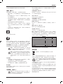
DWS780
电压 V
AC
220
类型 10
输入功率 瓦 1675
锯片直径 毫米 305
锯片内孔 毫米 30
叶身厚度 毫米 1.8
最大锯片转速 转/分 1900-3800
90° 最大横锯能力 毫米 349
45° 最大斜锯能力 毫米 244
90° 最大锯深 毫米 112
45° 最大斜面横锯深度 毫米 56
斜角切(最大位置) 左 50°
右 60°
斜面切(最大位置) 左 49°
右 49°
0° 斜角切
最大高度 112 毫米时成形宽度 毫米 299
最大高度 110 毫米时成形宽度 毫米 303
最大宽度 345 毫米时成形高度 毫米 76
45° 左侧斜角切
最大高度 112 毫米时成形宽度 毫米 200
最大宽度 244 毫米时成形高度 毫米 76
45° 右侧斜角切
最大高度 112 毫米时成形宽度 毫米 211
最大宽度 244 毫米时成形高度 毫米 76
45° 左侧斜面切
最大高度 63 毫米时成形宽度 毫米 268
最大宽度 345 毫米时成形高度 毫米 44
45° 右侧斜面切
最大高度 62 毫米时成形宽度 毫米 193
最大宽度 345 毫米时成形高度 毫米 28
锯片自动制动时间 秒 < 10
重量 千克 25.4
L
PA
(声压) dB(A) 93
K
PA
(声压不确定度) dB(A) 3.0
L
WA
(声音功率) dB(A) 100
K
WA
(声功率不确定度) dB(A) 3.0
总振动值(三轴矢量和)根据EN 61029决定:
振动发射值 安时 (a
h
)
a
h
= m/s
2
< 2.5
不确定度 K = m/s
2
1.5
斜切锯
DWS780
祝贺您!
您已选择了得伟工具。凭借多年的经验和不懈的产品开发与创新,得
伟已经成为专业电动工具用户的最可靠伙伴之一。
技术数据
本信息表中所载的振动发射标准依据 EN 61029 提供的标准测试测量,
并且可用于工具间的比较。它可用于振动接触的初步评估。
警告:我们所公布的振动发射标准适用于本工具的主要
应用。然而,如果将本工具用于其他应用、为其使用不
同的配件或保养不当,则振动发射值可能会不同。这可
能会大幅度提高总工作时间内的接触水平。
在关闭工具电源、或运行中的工具实际上并未工作时,
也应考虑到其振动的接触水平。这可大大降低总工作时
间内的振动接触水平。
20
ページが読み込まれています...
ページが読み込まれています...
ページが読み込まれています...
ページが読み込まれています...
ページが読み込まれています...
ページが読み込まれています...
ページが読み込まれています...
ページが読み込まれています...
ページが読み込まれています...
ページが読み込まれています...
ページが読み込まれています...
ページが読み込まれています...
ページが読み込まれています...
ページが読み込まれています...
ページが読み込まれています...
ページが読み込まれています...
ページが読み込まれています...
ページが読み込まれています...
ページが読み込まれています...
ページが読み込まれています...
-
 1
1
-
 2
2
-
 3
3
-
 4
4
-
 5
5
-
 6
6
-
 7
7
-
 8
8
-
 9
9
-
 10
10
-
 11
11
-
 12
12
-
 13
13
-
 14
14
-
 15
15
-
 16
16
-
 17
17
-
 18
18
-
 19
19
-
 20
20
-
 21
21
-
 22
22
-
 23
23
-
 24
24
-
 25
25
-
 26
26
-
 27
27
-
 28
28
-
 29
29
-
 30
30
-
 31
31
-
 32
32
-
 33
33
-
 34
34
-
 35
35
-
 36
36
-
 37
37
-
 38
38
-
 39
39
-
 40
40


他の言語で
- English: DeWalt DWS780 User manual
関連論文
その他のドキュメント
-
Hilti SC 70W-A22 Cordless Circular Saw ユーザーマニュアル
-
Stanley STEL721 ユーザーマニュアル
-
-
-
Bosch GCM 216 Professional Mitre Saw ユーザーマニュアル
-
Bosch GCM 18V-305 ユーザーマニュアル
-
Hikoki C 12LSH ユーザーマニュアル
-
-
BLACK+DECKER KS701E ユーザーマニュアル
-
Makita M3602 ユーザーマニュアル