
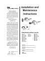
PRE-RINSE SPRAY VALVE
Limited One Year Warranty
(Commercial Applications)
T&S warrants to the original purchaser (other
than for purposes of resale) that such product is
free from defects in material and workmanship for
a period of one (1) year from the date of purchase.
During this one-year warranty period, if the product
is found to be defective, T&S shall, at its options,
repair and/or replace it. To obtain warranty service,
products must be returned to...
T&S Brass and Bronze Works, Inc.
Attn: Warranty Repair Department
2 Saddleback Cove
Travelers Rest, SC 29690
Shipping, freight, insurance, and other
transportation charges of the product to T&S and
the return of repaired or replaced product to the
purchaser are the responsibility of the purchaser.
Repair and/or replacement shall be made within
a reasonable time after receipt by T&S of the
returned product. This warranty does not cover
Items which have received secondary fi nishing or
have been altered or modifi ed after purchase, or
for defects caused by physical abuse to or misuse
of the product, or shipment of the products.
Any express warranty not provided herein, and
any remedy for Breach of Contract which might
arise, is hereby excluded and disclaimed. Any
implied warranties of merchantability or fi tness
for a particular purpose are limited to one year in
duration. Under no circumstances shall T&S be
liable for loss of use or any special consequential
costs, expenses or damages.
Some states do not allow limitations on how
long and implied warranty lasts or the exclusion or
limitation of incidental or consequential damages,
so the above limitations or exclusions may not
apply to you. Specifi c rights under this warranty
and other rights vary from state to state.
Attention California Residents:
WARNING This product can expose
you to chemicals including Lead, Chromium
(hexavalent compounds) and Phthalates
(DEHP) which are known to the State of
California to cause cancer and birth defects or
other reproductive harm.
For more information go to
www.P65Warnings.ca.gov.
P/N: 098-011027-45 Rev.12
Date: 10-09-19
Drawn: TED
Checked: JRM 11-11-19
Approved: JHB 02-14-20
Installation and
Maintenance
Instructions
B-0107
B-0107-035
B-0107-090
B-0107-C
B-0107-C35
B-0107-C90
B-0107-J
B-0107-J90
EB-0107
EB-0107-C
EB-0107-C35
EB-0107-J
EB-10K
EB-10K-C
EB-10K-J
B-10K
B-10K-C
B-10K-J
Español:
Instrucciones de instalación y mantenimiento
Français:
Instructions pour l’installation et la maintenance
Deutsch:
Installations- und Wartungsanleitungen
Italiano:
Istruzioni di installazione e manutenzione
中文:
安装与维护说明

2
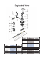
Exploded View
Model
Flow (gpm) [L/min]
Force (ozf) [N]
B-0107-C
0.65 [2.5]
4.4 [1.2]
B-0107-C35
0.65 [2.5]
4.4 [1.2]
B-0107-C90
0.65 [2.5]
4.4 [1.2]
B-10K-C
0.65 [2.5]
4.4 [1.2]
EB-0107-C
0.65 [2.5]
4.4 [1.2]
EB-0107-C35
0.65 [2.5]
4.4 [1.2]
EB-10K-C
0.65 [2.5]
4.4 [1.2]
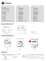
EB-0107 5.60 [21.2] 8.3 [2.3]
EB-0107-035 5.60 [21.2] 8.3 [2.3]
EB-10K 5.60 [21.2] 8.3 [2.3]
EB-10K-J 1.15 [4.4] 7.5 [2.1]
B-0107 1.15 [4.4] 7.5 [2.1]
B-0107-035 1.15 [4.4] 7.5 [2.1]
B-0107-090 1.15 [4.4] 7.5 [2.1]
B-10K 1.15 [4.4] 7.5 [2.1]
Model
Flow (gpm) [L/min]
Force (ozf) [N]
B-0107-J 1.07 [4.1] 7.2 [2.0]
B-0107-J90 1.07 [4.1] 7.2 [2.0]
B-10K-J 1.07 [4.1] 7.2 [2.0]
EB-0107-J 1.07 [4.1] 7.2 [2.0]

3
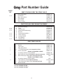
Grey
Grey Part Number Guide
PARTS FOR ANY GREY T&S SPRAY VALVE
1
2
3
4
5
6
Ring, Hold Down
#27 Washer
Body, Spray Valve
Grey Handle
Nut, Handle
Screw, Handle
000907-45
010476-45
000065-40
001120-45
003198-45
003199-45
7
8
9
10
11
22
23
24
22
23
24
25
B-0107 (1.15 GPM 7.5 Ozf)
Nipple
Cup, Spray
Ring, Sprayhead
1.15 GPM Sprayface (1.15 Stamped on Face)
Screw, Sprayface
B-0107-C (0.65 GPM 4.4 Ozf)
Assembly, B-0107-C Spray Nozzle
0.65 GPM Grey Shield (No Outline Around Lettering)
0.65 GPM Spray Nozzle (0.65 Stamped on Face)
B-0107-J (1.07 GPM 7.2 Ozf)
Assembly, B-0107-J Spray Nozzle
1.07 GPM Grey Shield (Square Outline)
1.07 GPM Spray Nozzle (1.07 Stamped on Face)
Nozzle Holder
000694-40
000019-40
007861-45
001121-45
000913-45
002662-40
002659-45NS
N/A
N/A
018292-45NS
N/A
N/A
Bonnet Assembly
Stem
Washer, Seat
Washer, Bonnet Binding
Bonnet
Washer, Bonnet Brass
Stem, Packing
Spring, Bonnet
Push Button
Grease Pack
002856-40
009306-20
012915-45
001040-45
000608-25
000974-45
001100-45
000895-45
000753-25
012665-45
12
13
14
15
16
17
18
19
20
21
1,2,3
PARTS
KIT
1,2,3
1,2,3
1,2,3
1,2,3
1,2,3
1,2,3
1,2,3
PARTS FOR ANY GREY BONNET ASSEMBLY
GREY SPRAY VALVES
1
1
1
2
3
#1 Parts included in B-10K
#2 Parts included in B-10K-C
#3 Parts included in B-10K-J

4
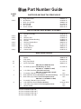
Blue
Blue Part Number Guide
PARTS FOR ANY BLUE T&S SPRAY VALVE
1
2
3
4
5
6
Ring, Hold Down
#27 Washer
Body, Spray Valve
Blue Handle
Nut, Handle
Screw, Handle
000907-45
010476-45
000065-40
011454-45
003198-45
003199-45
7
8
9
11
10
10
22
23
24
22
23
24
25
EB-0107 & UK-0107 Only
Nipple
Cup, Spray
Ring, Sprayhead
Screw, Sprayface
EB-0107 (5.6 GPM 8.3 Ozf)
5.6 GPM Sprayface (No Wording on Face)
UK-0107 (1.15 GPM 7.5 Ozf)
1.15 GPM Sprayface (Flow Rate on Face)
EB-0107-C (0.65 GPM 4.4 Ozf)
Assembly, EB-0107-C Spray Nozzle
0.65 GPM Blue Shield (No Outline Around Lettering)
0.65 GPM Spray Nozzle (0.65 Stamped on Face)
EB-0107-J (1.07 GPM 7.2 Ozf)
Assembly, EB-0107-J Spray Nozzle
1.07 GPM Blue Shield (Square Outline)
1.07 GPM Spray Nozzle (1.07 Stamped on Face)
Nozzle Holder
000694-40
000019-40
011475-45
000913-45
011456-45
N/A
N/A
011499-45NS
N/A
N/A
018293-45NS
N/A
N/A
Bonnet Assembly
Stem
Washer, Seat
Washer, Bonnet Binding
Bonnet
Washer, Bonnet Brass
Quad Seal
Spring, Bonnet
Push Button
Grease Pack
010594-40
009306-20
010563-45
010565-45
000608-25
000974-45
014615-45
000895-45
000753-25
010573-45
12
13
14
15
16
17
18
19
20
21
4,5,6,7
PARTS
KIT
4,5,6,7
4,5,6,7
4,5,6,7
4,5,6,7
4,5,6,7
4,5,6,7
4,5,6,7
PARTS FOR ANY BLUE BONNET ASSEMBLY
BLUE SPRAY VALVES
4,7
4,7
4
7
5
6
#4 Parts included in EB-10K
#5 Parts included in EB-10K-C
#6 Parts included in EB-10K-J
#7 Parts included in UK-10K

5
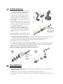
To replace worn parts:
1. Shut o water supply and drain lines. For
ease of disassembly and reassembly, the
handle grip can be removed from no.3.
2. Unscrew no.5 and no.6 to remove no.4.
Unscrew and remove no.16 from no.3.
3. Hold no.20 with pliers in one hand, and
with screwdriver, carefully unscrew no.13
from no.16.
4. Apply no.21 over smooth portion of no.13.
Replace no.14, no.15, no.17, no.18 & no.19
with new parts. Dab no.21 onto valve side
of no.19 before replacing.
5. Reassemble no.16 by inserting no.13
through all parts. Hold no.20 with pliers,
and carefully screw no.13 into no.20 until
screw feels tight. Do not use excessive
force.
6. Reinsert no.16 in no.3 and tighten securely.
7. Reassemble no.4, no.5 and no.6 on no.3.
3
1620
5
6
4
16
14
13
18
19
20
17
15
13
apply no.21 here
Aplique aquí el n.° 21
appliquez le No 21 ici
Nr. 21 hier ansetzen
applicare il n. 21 qui
在此处涂抹编号 21
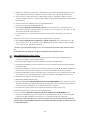
8. For EB-0107/UK-0107 & B-0107 ONLY: To replace no.9, unscrew no.11 and disassemble. Make
sure the groove side of no.9 ts over no.8, and no.10 rest on ridge side. See Figure A.
9. To replace no.2, unscrew handle grip from no.3 and replace with new no.2.
10. Reassemble; turn on water check for leaks.
11. For EB-0107-C, EB-0107-J,B-0107-C & B-0107-J ONLY: To replace no.23, slide no.23 o no.25,
and slide a new no.23 back onto no.25. No.23 will snap into groove on no.25. See Figure B.
* Verify the ow rate on no.23 matches spray tip inside no.25.
Caution: Turn o water supply at base faucet when not in use.
A
11
10
9
8
1
3
2
handle grip
Mango de la manija
poignée
Handgri
impugnatura
手柄把手
25
EN
ES
23
B
Para reemplazar las
piezas desgastadas:
1. Corte el suministro de agua y drene las líneas. Para facilitar el desarmado yarmado, el mango de la
manija se puede quitar del n.° 3.
2. Destornille el n.° 5 y n.° 6 para quitar eln.° 4. Destornille y quite el n.° 16 deln.° 3.
3. Con una mano sostenga el n.° 20 conpinzas y con el destornillador quite cuidadosamente el n.° 13
del n.°16.

6
4. Aplique el n.° 21 sobre una parte del n.° 13. Reemplace los números 14, 15, 17, 18 y 19 con partes
nuevas. Golpee ligeramente el n.° 21 por el lado de la válvula del n.° 19 antes dereemplazarlo.
5. Vuela a armar el n.° 16 insertando eln.° 13 por todas las partes. Sostenga el n.° 20 con pinzas y
atornille cuidadosamente el n.° 13 dentro deln.°20 hasta que el tornillo quede ajustado. No aplique
fuerza excesiva.
6. Vuelva a insertar el n.° 16 dentro deln.° 3 y ajuste rmemente.
7. Vuelva a armar los números 4, 5 y 6 en el n.° 3.
8. ÚNICAMENTE PARA EB-0107/UK-0107 y B-0107 : Para reemplazar el n.° 9, destornille el n.°
11 y desarme. Asegúrese de que el lado de la ranura del n.° 9 seajuste al n.° 8, yque el n.° 10
descanse enelborde. Véase la gura A.
9. Para reemplazar el n.° 2, destornille el mango de la manija del n.° 3 yreemplace con el n.° 2
nuevo.
10. Vuelva a armar; abra el suministro deagua y veri que que no haya fugas.
11. ÚNICAMENTE PARA EB-0107-C, EB-0107-J, B-0107-C y B-0107-J: Para reemplazar el n.° 23,
deslícelo fuera del n.° 25 e introduzca un n.°23 nuevo dentro del n.° 25. Eln.°23 se insertará
en la ranura enel n.° 25. Véase la gura B.
* Veri que que la velocidad del ujo en el n.° 23 coincida con la punta deaspersión dentro del n.°
25.
Precaución: Corte el suministro de agua en el grifo de base cuando no lo use.
Pour remplacer les pièces usées :
1. Coupez l'alimentation en eau et les conduites d'évacuation. Pour faciliter le démontage et le
remontage, la poignée peut être retirée du No 3.
2. Dévissez les No 5 et 6 pour retirer le No 4. Dévissez et retirer le No 16 duNo3.
3. Immobilisez le No 20 avec une pince d'une main, et avec un tournevis, dévissez soigneusement le
No 13 duNo 16.
4. Appliquez le No 21 sur la portion lisse du No 13. Remplacez les No14, 15, 17, 18 et 19 par des
pièces neuves. Tamponnez le No 21 sur le côté vanne du No 19 avant leremplacement.
5. Remontez le No 16 en insérant le No13 au travers de toutes les pièces. Immobilisez le No 20
avec une pince, et vissez soigneusement à fond le No13 dans le No 20. Ne serrez pastrop.
6. Réinsérez le No 16 dans le No 3 etbien serrer.
7. Remontez les No 4, 5 et 6 sur le No 3.
8. POUR LES RÉFÉRENCES EB-0107/UK-0107 & B-0107 UNIQUEMENT : Pour remplacer le No 9,
dévissez le No 11 et procédez au démontage. Véri ez que le côté rainure du No 9 s'adapte sur
le No8, et que le No 10 repose sur le côté del'arête. Voir la Figure A.
9. Pour remplacer le No 2, dévissez lapoignée du No 3 et installez un No2 neuf.
10. Remontez; Ouvrez l'arrivée d'eau, recherchez des fuites.
11. Pour les modèles EB-0107-C, EB-0107-J, B-0107-C & B-0107-J UNIQUEMENT: Pour
remplacer le No23, faites glisser le No 23
hors du No 25, et faites glisser un nouveau No 23
neuf sur le No 25. Le No 23 s'enclenche dans la saignée du No25. Voir la gure B.
* Véri ez que le débit sur le No23 correspond à l'embout de pulvérisation à l'intérieur du No 25.
Avertissement: Coupez l'alimentation en eau au robinet de la base lorsque le modèle n'estpas
en cours d'utilisation.
FR

7
Verschleißteile ersetzen:
1. Wasserzufuhr ausschalten und Rohre entleeren. Zum leichten Aus- und Einbau kann der
Handgri von Nr. 3 entfernt werden.
2. Nr. 5 und Nr. 6 abschrauben, um
Nr. 4 zu entfernen. Nr. 16 aufschrauben und von Nr. 3 entfernen.
3. Nr. 20 mit der Zange in einer Hand halten und mit dem Schraubenzieher vorsichtig Nr.13 von
Nr. 16 abschrauben.
4. Nr. 21 auf dem glatten Teil von Nr.13 anbringen. Nr.14, Nr.15, Nr.17, Nr.18 & Nr.19 durch
neue Teile ersetzen. Nr.21 auf Ventilseite von Nr.19 vor dem Ersetzen abtupfen.
5. Nr. 21 auf dem glatten Teil von Nr.13 anbringen. Nr.14, Nr.15, Nr.17, Nr.18 & Nr.19 durch
neue Teile ersetzen. Nr.21 auf Ventilseite von Nr.19 vor dem Ersetzen abtupfen.
6. Nr.16 durch Einführen von Nr. 13 durch alle Teile wieder zusammenbauen. Nr. 20 mit der Zange in
einer Hand halten und vorsichtig Nr.13 in Nr.20 schrauben bis es fest sitzt. Keine übermäßige Gewalt
anwenden.
7. Nr. 16 in Nr. 3 wieder einstecken undfest anziehen.
8. Nr. 4, Nr. 5 und Nr. 6 wieder auf Nr. 3 zusammenbauen.
9. NUR für EB-0107/UK-0107 & B-0107: Um Nr. 9
zu ersetzen, Nr.11 abschrauben und ausbauen.
Sicherstellen, dass Rillenseite von Nr.9 über Nr. 8 passt und Nr. 10 auf der starren Seite ruht. Siehe
Abbildung A.
10. Um Nr. 2 zu ersetzen, Nr. 3 vom Handgri abschrauben und mit einer neuen Nr. 2 ersetzen.
11. Wieder zusammenbauen, Wasserzufuhr anschalten und aufLeckagen prüfen.
12. NUR für EB-0107-C, EB-0107-J, B-0107-C & B-0107-J: Um Nr.23 zu ersetzen, Nr. 23 von Nr. 25
abnehmen und eine neue Nr. 23 wieder zurück auf Nr. 25 setzen. Nr. 23 wieder in die Rille auf
Nr. 25 einrasten. Siehe Abbildung B.
* Prüfen ob der Durch uss an Nr.23 mit der Spritzdüse in Nr. 25 übereinstimmt.
ACHTUNG: Wasserzufuhr an der grundlegenden Armatur abstellen, wenn nicht in Gebrauch.
Per sostituire le parti usurate:
1. Chiudere la fornitura idrica e le linee di drenaggio. Per facilità di smontaggio e rimontaggio,
l’impugnatura può essere rimossa dal n. 3.
2. Svitare n. 5 e n. 6 per rimuovere il n.4. Svitare e rimuovere il n. 16 dal n. 3.
3. Mantenere il n. 20 con le pinze in una mano e, con il cacciavite, svitare attentamente il n. 13
dal n. 16.
4. Applicare il n. 21 sulla porzione liscia del n. 13. Sostituire il n. 14, n. 15, n. 17, n. 18 e il n. 19 con
parti nuove. Picchiettare il n. 21 sul lato valvola deln. 19 prima della sostituzione.
5. Riassemblare il n. 16 facendo passare il n. 13 attraverso tutte le parti. Mantenere il n. 20 con
le pinze, e avvitare con cura il n. 13 nel n. 20 no a che la vite non risulta ben serrata. Non
utilizzare forza eccessiva.
6. Reinserire il n. 16 nel n. 3 e serrare con fermezza.
7. Riassemblare il n. 4, il n. 5 e il n. 6 sul n. 3.
8. SOLO per EB-0107/UK-0107 & B-0107 : Per sostituire il n. 9, svitare il n. 11 e smontare.
Accertarsi che il lato scanalato del n. 9 entri nel n. 8, e che il n. 10 sia appoggiato sul lato
dorsale. Vedere la Figura A.
9. Per sostituire il n. 2, svitare l’impugnatura dal n. 3 e sostituire con il nuovo n. 2.
10. Riassemblare; attivare il controllo idrico per le perdite.
DE
IT

8
更换磨损件:
1. 关闭供水及下水管道,为了便于拆卸和重新组装,可先将手把从3号上拆卸下来。
2. 拧下5号和6号以便拆下4号。从3号上拧下16号。
3. 一只手用钳子夹住20号,用螺丝刀小心地将13号从16号上卸下。
4. 将21号涂在13号的光滑部分。用新零件替换14号、15号、17号、18号和19号。替换前
将21号少量涂抹在19号的阀门侧。
5. 将13号穿过所有零件以重新组装16号。用钳子夹住20号,小心地将13号拧到20号上,
直到拧紧为止。请勿用力过度。
6. 将16号重新插入3号中,并拧紧。
7. 将4号、5号和6号重新装在3号上。
8. 仅适用于EB-0107/UK-0107 和B-0107:要替换9号,先拧下11号并拆开。请确保8号
正好卡在9号的凹槽侧,10号安放在凸棱侧。详见图A。
9. 如需更换2号,先将手把从3号上拧下,再用新的2号进行替换。
10. 重新组装;打开供水检查是否漏水。
11. 仅适用于EB-0107-C, EB-0107-J, B-0107-C和B-0107-J:如需更换23号,先从25号
上摘下23号,再在25号上重新套上一个新的23号,23
号要卡在25号的凹槽中。详见图
B。
*请确认23号上标的流量与25号内的喷头相匹配。
注意:不使用龙头时,请关闭底座上的供水。
CN
11. SOLO per EB-0107-C, EB-0107-J, B-0107-C E B-0107-J: Per sostituire il n. 23, fare scorrere
il n. 23 dal n. 25, e fare scorrere nuovamente un nuovo n. 23 nel n. 25. Il n. 23 scatterà nella
scanalatura del n. 25. Vedere la Figura B.
* Veri care che la portata sul n. 23 corrisponda al puntale a spruzzo all’interno del n. 25.
Attenzione: disattivare la fornitura idrica al rubinetto della base quando non è in uso.

T&S BRASS AND BRONZE WORKS, INC.
A fi rm commitment to application-engineered plumbing products
2 Saddleback Cove, P.O. Box 1088, T & S Brass-Europe
Travelers Rest, SC 29690 ‘De Veenhoeve’
Phone: (864) 834-4102 Oude Nieuwveenseweg 84
Fax: (864) 834-3518 2441 CW Nieuwveen
E-mail:
[email protected] The Netherlands
B-0108
JeTSpray
Spray Valve
RELATED T&S BRASS PRODUCT LINE
B-0108-C
JeTSpray
Low Flow
Spray Valve
-
 1
1
-
 2
2
-
 3
3
-
 4
4
-
 5
5
-
 6
6
-
 7
7
-
 8
8
-
 9
9


他の言語で
- italiano: T&S BRASS EB-0107-J-HM12 Manuale utente
- français: T&S BRASS EB-0107-J-HM12 Manuel utilisateur
- English: T&S BRASS EB-0107-J-HM12 User manual
その他のドキュメント
-
 Bitspower BP-D5TMPSV2-BKMBK インストールガイド
-
 Bitspower BP-D5VP インストールガイド
-
Belle Foret SN-WHRO102WH インストールガイド
-
Renishaw XCal-View ユーザーガイド
-
-
Korg EXBPCM04 取扱説明書
-
Bosch AJ-114 ユーザーマニュアル
-
Greenlee PVA0021, PVA0022 Hydraulic Control Valves-Chinese ユーザーマニュアル
-
-

