
D25413
D25414
D25415
D25430

B
Copyright DE WALT
3
12
21
30
39
48
57
English (original instructions)
中文 (简体)
中文(繁體)
B A H ASA INDO N E SIA
tiếng việt
ภาษาไทย

1
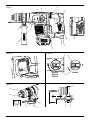
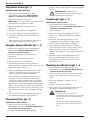
Figure 1
a
o
b
f
k
j
l
d
e
c
h
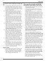
Figure 2
i
Figure 4
k
j
g
n
f
Figure 3
d
e
D25430D25413
D25414
D25415

2
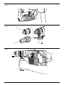
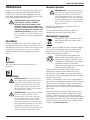
Figure 5
Figure 6
Figure 7
c
b
f
l
m
g

English
3
Congratulations!
You have chosen a DeWALT tool. Years of experience, thorough product development and innovation make
DeWALT one of the most reliable partners for professional power tool users.
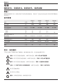
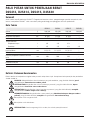
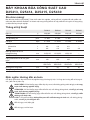
Technical Data
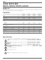
D25413 D25414 D25415 D25430
Voltage V 220-240 220-240 220-240 220-240
Power Input W 1000 1000 1000 1000
No load speed min
-1
0 – 820 0 – 820 0 – 820 –
Beats per minute bpm 0 – 4700 0 – 4700 0 – 4700 0 – 4700
Impact energy
Hammerdrilling J 4.9 4.9 4.9 –
Chiselling J 4.9 4.9 4.9 4.9
Maximum drilling range in
steel/wood/concrete mm 13 / 32 / 32 13 / 32 / 32 13 / 32 / 32 –
Chisel positions 12 12 12 12
Core drilling capacity in soft brick mm 100 100 100 –
Tool holder SDS Plus
®
SDS Plus
®
SDS Plus
®
SDS Plus
®
Collar diameter mm 60 60 60 60
Weight kg 4.2 4.3 4.3 4.0
Definitions: Safety Guidelines
The definitions below describe the level of severity for each signal word. Please read the manual and pay
attention to these symbols.
DANGER: Indicates an imminently
hazardous situation which, if not avoided, will result in death or serious injury.
WARNING: Indicates a potentially hazardous situation which, if not avoided, could result in
death or serious injury.
CAUTION: Indicates a potentially hazardous situation which, if not avoided, may result in minor
or moderate injury.
NOTICE: Indicates a practice not related to personal injury which, if not avoided, may result
in property damage.
Denotes risk of electric shock.
Denotes risk of fire.
WARNING: To reduce the risk of injury, read the instruction manual.
HEAVY-DUTY ROTARY HAMMER
D25413, D25414, D25415, D25430
English (original instructions)

4
English
3) PERSONAL SAFETY
a) Stay alert, watch what you are doing and
use common sense when operating a
power tool. Do not use a power tool while
you are tired or under the influence of
drugs, alcohol or medication. A moment of
inattention while operating power tools may
result in serious personal injury.
b) Use personal protective equipment.
Always wear eye protection. Protective
equipment such as dust mask, non-skid
safety shoes, hard hat, or hearing protection
used for appropriate conditions will reduce
personal injuries.
c) Prevent unintentional starting. Ensure
the switch is in the off position before
connecting to power source and/or
battery pack, picking up or carrying the
tool. Carrying power tools with your finger
on the switch or energising power tools that
have the switch on invites accidents.
d) Remove any adjusting key or wrench
before turning the power tool on. A
wrench or a key left attached to a rotating
part of the power tool may result in personal
injury.
e) Do not overreach. Keep proper
footing and balance at all times. This
enables better control of the power tool in
unexpected situations.
f) Dress properly. Do not wear loose
clothing or jewellery. Keep your hair,
clothing and gloves away from moving
parts. Loose clothes, jewellery or long hair
can be caught in moving parts.
g) If devices are provided for the connection
of dust extraction and collection facilities,
ensure these are connected and properly
used. Use of dust collection can reduce
dust-related hazards.
4) POWER TOOL USE AND CARE
a) Do not force the power tool. Use the
correct power tool for your application.
The correct power tool will do the job
better and safer at the rate for which it
was designed.
b) Do not use the power tool if the switch
does not turn it on and off. Any power
tool that cannot be controlled with the switch
is dangerous and must be repaired.
c) Disconnect the plug from the power
source and/or the battery pack from
the power tool before making any
adjustments, changing accessories, or
storing power tools. Such preventive safety
measures reduce the risk of starting the
power tool accidentally.
General Power Tool Safety Warnings
WARNING! Read all safety warnings
and all instructions. Failure to follow
the warnings and instructions may result
in electric shock, fire and/or serious
injury.
Save all warningS and inStructionS
for future reference
The term “power tool” in the warnings refers to
your mains-operated (corded) power tool or
battery-operated (cordless) power tool.
1) WORK AREA SAFETY
a) Keep work area clean and well lit.
Cluttered or dark areas invite accidents.
b) Do not operate power tools in explosive
atmospheres, such as in the presence of
flammable liquids, gases or dust. Power
tools create sparks which may ignite the dust
or fumes.
c) Keep children and bystanders away while
operating a power tool. Distractions can
cause you to lose control.
2) ELECTRICAL SAFETY
a) Power tool plugs must match the outlet.
Never modify the plug in any way. Do
not use any adapter plugs with earthed
(grounded) power tools. Unmodified plugs
and matching outlets will reduce risk of
electric shock.
b) Avoid body contact with earthed or
grounded surfaces such as pipes,
radiators, ranges and refrigerators. There
is an increased risk of electric shock if your
body is earthed or grounded.
c) Do not expose power tools to rain or wet
conditions. Water entering a power tool will
increase the risk of electric shock.
d) Do not abuse the cord. Never use the
cord for carrying, pulling or unplugging
the power tool. Keep cord away from
heat, oil, sharp edges or moving parts.
Damaged or entangled cords increase the
risk of electric shock.
e) When operating a power tool outdoors,
use an extension cord suitable for outdoor
use. Use of a cord suitable for outdoor use
reduces the risk of electric shock.
f) If operating a power tool in a damp
location is unavoidable, use a residual
current device (RCD) protected supply.
Use of an RCD reduces the risk of electric
shock.

5
English
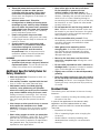
• Keep a firm grip on the tool at all times.
Do not attempt to operate this tool
without holding it with both hands. It is
recommended that the side handle be used at
all times. Operating this tool with one hand will
result in loss of control. Breaking through or
encountering hard materials such as re-bar may
be hazardous as well. Tighten the side handle
securely before use.
• Do not operate this tool for long periods of
time. Vibration caused by hammer action may
be harmful to your hands and arms. Use gloves
to provide extra cushion and limit exposure by
taking frequent rest periods.
• Do not recondition bits yourself. Chisel
reconditioning should be done by an authorized
specialist. Improperly reconditioned chisels
could cause injury.
• Wear gloves when operating tool or
changing bits. Accessible metal parts on the
tool and bits may get extremely hot during
operation. Small bits of broken material may
damage bare hands.
• Never lay the tool down until the bit has
come to a complete stop. Moving bits could
cause injury.
• Do not strike jammed bits with a hammer to
dislodge them. Fragments of metal or material
chips could dislodge and cause injury.
• Slightly worn chisels can be resharpened by
grinding.
• Keep the power cord away from the rotating
bit. Do not wrap the cord around any part of
your body. An electric cord wrapped around a
spinning bit may cause personal injury and loss
of control.
Residual Risks
The following risks are inherent to the use of rotary
hammers:
– injuries caused by touching the rotating parts or
hot parts of the tool.
In spite of the application of the relevant safety
regulations and the implementation of safety
devices, certain residual risks cannot be avoided.
These are:
– Impairment of hearing.
– Risk of squeezing fingers when changing the
accessory.
– Health hazards caused by breathing dust
developed when working in concrete and/or
masonry.
d) Store idle power tools out of the reach
of children and do not allow persons
unfamiliar with the power tool or these
instructions to operate the power tool.
Power tools are dangerous in the hands of
untrained users.
e) Maintain power tools. Check for
misalignment or binding of moving parts,
breakage of parts and any other condition
that may affect the power tool’s operation.
If damaged, have the power tool repaired
before use. Many accidents are caused by
poorly maintained power tools.
f) Keep cutting tools sharp and clean.
Properly maintained cutting tools with sharp
cutting edges are less likely to bind and are
easier to control.
g) Use the power tool, accessories and
tool bits etc., in accordance with these
instructions taking into account the
working conditions and the work to
be performed. Use of the power tool for
operations different from those intended
could result in a hazardous situation.
5) SERVICE
a) Have your power tool serviced by a
qualified repair person using only identical
replacement parts. This will ensure that the
safety of the power tool is maintained.
Additional Specific Safety Rules for
Rotary Hammers
• Wear ear protectors. Exposure to noise can
cause hearing loss.
• Useauxiliaryhandlessuppliedwiththetool.
Loss of control can cause personal injury.
• Hold power tool by insulated gripping
surfaces, when performing an operation
where the cutting accessory or the fastener
may contact hidden wiring or its own cord.
Cutting accessory contacting a “live” wire may
make exposed metal parts of the power tool
“live” and could give the operator an electric
shock.
• Use clamps or other practical way to secure
and support the workpiece to a stable
platform. Holding the work by hand or against
your body is unstable and may lead to loss of
control.
• Wear safety goggles or other eye protection.
Hammering operations cause chips to fly. Flying
particles can cause permanent eye damage.
Wear a dust mask or respirator for applications
that generate dust. Ear protection may be
required for most applications.

6
English
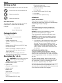
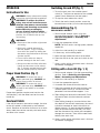
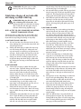
j. Depth adjustment rod
(D25413, D25414, D25415 only)
k. Depth stop clamp
l. Locking collar
m. Chuck (D25414 and D25415 only)
n. Dust cover
o. Lock on button (D25430 only)
INTENDED USE
D25413, D25414, D25415
These heavy-duty rotary hammers have been
designed for professional drilling and hammerdrilling,
screwdriving and light chipping.
D25430
This chipping hammer has been designed for
professional chipping, chiselling and demolition
applications.
DO NOT use under wet conditions or in the
presence of flammable liquids or gases.
These hammerdrills are professional power tools.
DO NOT let children come into contact with the
tool. Supervision is required when inexperienced
operators use this tool.
• Thisproductisnotintendedforusebypersons
(including children) suffering from diminished
physical, sensory or mental abilities; lack of
experience, knowledge or skills unless they are
supervised by a person responsible for their
safety. Children should never be left alone with
this product.
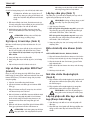
ACTIVE VIBRATION CONTROL (FIG. 1)
The active vibration control neutralises rebound
vibration from the hammer mechanism. Lowering
hand and arm vibration allows for more comfortable
use for longer periods of time and extends the life of
the unit.
For best vibration control, hold the tool with one
hand on the main handle (b) and the other hand on
the side handle (f). Apply just enough pressure so
the hammer is approximately mid-stroke.
The hammer only needs enough pressure to engage
the active vibraton control. Applying too much
pressure will not make the tool drill or chip faster and
active vibration control will not engage.
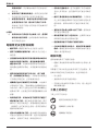
Markings on Tool
The following pictograms are shown on the tool:
Read instruction manual before use.
Wear ear protection.
Wear eye protection.
DATE CODE POSITION
The date code, which also includes the year of
manufacture, is printed into the housing.
Example:
2013 XX XX
Year of Manufacture
Package Contents
The package contains:
1 Heavy-duty rotary hammerdrill
1 Side handle
1 Depth adjustment rod
(D25413, D25414, D25415 only)
1 Kitbox
1 Keyless chuck (D25414 and D25415 only)
1 Instruction manual
• Checkfordamagetothetool,partsor
accessories which may have occurred
during transport.
• Takethetimetothoroughlyreadand
understand this manual prior to operation.
Description (fig. 1–4, 6)
WARNING: Never modify the power
tool or any part of it. Damage or
personal injury could result.
a. Variable speed switch
b. Main handle
c. Forward / reverse slider
d. Mode selector
e. Safety lock
f. Side handle
g. Tool holder / locking sleeve
h. Shocks
i. LED Indicator (D25415 only)

7
English
ASSEMBLY AND ADJUSTMENTS
WARNING: To reduce the risk of
injury, turn unit off and disconnect
machine from power source before
installing and removing accessories,
before adjusting or changing
set-ups or when making repairs.
Be sure the trigger switch is in the OFF
position. An accidental start-up can
cause injury.
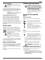
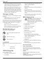
Selecting the Operating Mode
(fig. 3)
D25413, D25414, D25415
The tool can be used in the following operating
modes:
Rotary drilling: for screwdriving and for
drilling into steel, wood and plastics.
Hammerdrilling: for concrete and masonry
drilling operations.
Hammering only: for light chipping,
chiselling and demolition applications. In
this mode the tool can also be used as a
lever to free a jammed drill bit.
D25430
The tool can be used in the following operating
modes:
Hammering only: for light chipping,
chiselling and demolition applications. In
this mode the tool can also be used as a
lever to free a jammed drill bit.
1. To select the operating mode, press the safety
lock (e) and rotate the mode selector switch
(d) until it points to the symbol of the required
mode.
2. Release the safety lock and check that the
mode selector switch is locked in place.
WARNING: Do not select the operating
mode when the tool is running.
Indexing the Chisel Position (fig. 3)
The chisel can be indexed and locked into 12
different positions.
1. Rotate the mode selector switch (d) until it
points to the hammerdrill mode symbol. Refer to
Selecting the Operating Mode in Assembly
and Adjustments.
TORQUE LIMITING CLUTCH
WARNING: The user must always
maintain a firm grip on the tool when in
operation.
The torque limiting clutch reduces the maximum
torque reaction transmitted to the operator in case
of jamming of a drill bit. This feature also prevents
the gearing and electric motor from stalling.
NOTICE: Always turn the tool off before
changing torque control settings or
damage to tool may result.
ANTI ROTATION SYSTEM D25415 (FIG. 2)
The anti rotation system offers increased user
comfort and safety through an on-board, anti-
rotation technology capable of detecting if the
user loses control of the hammer. When a jam
is detected, the torque and speed are reduced
instantly. This feature prevents self rotation of the tool
reducing the occurrence of wrist injuries. The red
LED indicator (i) lights up if the anti-rotational device
is activated.
Electrical Safety
The electric motor has been designed for one
voltage only. Always check that the power supply
corresponds to the voltage on the rating plate.
Your DeWALT tool is double insulated in
accordance with EN 60745; therefore no
earth wire is required.
WARNING: 115 V units have to
be operated via a fail-safe isolating
transformer with an earth screen
between the primary and secondary
winding.
If the supply cord is damaged, it must be replaced
by a specially prepared cord available through the
DeWALT service organisation.
Using an Extension Cable
If an extension cable is required, use an approved
3–core extension cable suitable for the power input
of this tool (see Technical Data).The minimum
conductor size is 1.5 mm
2
; the maximum length
is 30 m.
When using a cable reel, always unwind the cable
completely.

8
English
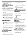
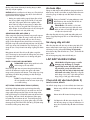
4. Adjust the drilling depth as shown.
5. Release the depth stop clamp.
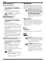
Forward/reverse Slider (fig. 5)
1. Push the forward/reverse slider (c) to the
LH-side for forward (RH) rotation. See arrows
on tool.
2. Push the forward/reverse slider (c) to the
RH-side for reverse (LH) rotation.
WARNING: Always wait until the motor
has come to a complete standstill
before changing the direction of rotation.
Fitting a Chuck Adapter and Chuck
(Sold Separately)
1. Screw a chuck onto the threaded end of the
chuck adapter.
2. Insert the connected chuck and adapter in the
tool as though it were a standard SDS Plus
®
bit.
3. To remove the chuck, proceed as for removing
a standard SDS Plus
®
bit.
WARNING: Never use standard chucks
in the hammerdrilling mode.
Consult your dealer for further information on the
appropriate accessories.
Replacing the Tool Holder with the
Chuck (fig. 6)
D25414 AND D25415 ONLY
1. Turn the locking collar (l) into the unlocking
position and pull the tool holder/locking
sleeve(g) off.
2. Push the chuck (m) onto the spindle and turn
the locking collar into the locking position.
3. To replace the chuck with the tool holder, first
remove the chuck the same way as the tool
holder was removed. Then place the tool holder
the same way as the chuck was placed.
WARNING: Never use standard chucks
in the hammerdrilling mode.
Replacing the Dust Cover (fig. 1, 4)
The dust cover (n) prevents dust ingress into the
mechanism. Replace a worn dust cover immediately.
1. Pull back the tool holder locking sleeve (g) and
pull the dust cover (n) off.
2. Fit the new dust cover.
3. Release the tool holder locking sleeve.
2. Rotate the chisel in the desired position.
3. Set the mode selector switch (d) to the
hammering only position.
4. Twist the chisel until it locks in position.
Inserting and Removing SDS Plus
®
Accessories (fig. 4)
This tool uses SDS Plus
®
accessories (refer to
the inset in figure 4 for a cross-section of an SDS
Plus
®
bit shank). We recommend using professional
accessories only.
1. Clean and grease the bit shank.
2. Insert the bit shank into the tool holder/locking
sleeve (g).
3. Push the bit down and turn it slightly until it fits
into the slots.
4. Pull on the bit to check if it is properly locked.
The hammering function requires the bit to be
able to move axially several centimetres when
locked in the tool holder.
5. To remove a bit, pull back the tool holder/
locking sleeve (g) and pull out the bit.
WARNING: Always wear gloves when
you change accessories. The exposed
metal parts on the tool and accessory
may become extremly hot during
operation.
Fitting the Side Handle (fig. 1)
The side handle (f) can be fitted to suit both RH- and
LH-users.
WARNING: Do not use the tool without
the side handle properly assembled.
1. Loosen the side handle.
2. For RH-users: slide the side handle clamp
over the collar behind the tool holder, handle at
the left.
For LH-users: slide the side handle clamp over
the collar behind the tool holder, handle at the
right.
3. Rotate the side handle to the desired position
and tighten the handle.
Setting the Drilling Depth (fig. 4)
D25413, D25414, D25415 ONLY
1. Insert the required drill bit as described above.
2. Press the depth stop clamp (k) and keep it
depressed.
3. Fit the depth adjustment rod (j) through the hole
in the depth stop clamp.

9
English
Switching On and Off (fig. 1)
1. To run the tool, press the variable speed
switch(a). The pressure exerted on the variable
speed switch determines the tool speed.
2. To stop the tool, release the switch.
3. To lock the tool in the off position, move the
forward/reverse slider (c) to the central position.
Hammerdrilling (fig. 1)
DRILLING WITH A SOLID BIT
1. Set the mode selector switch (d) to the
hammerdrilling position. Refer to Selecting
the Operating Mode in Assembly and
Adjustments.
2. Insert the appropriate drill bit.
NOTE: For best results use high quality carbide-
tipped bits.
3. Adjust the side handle (f) as required.
4. If necessary, set the drilling depth.
5. Mark the spot where the hole is to be drilled.
6. Place the drill bit on the spot and switch on the
tool.
7. Always switch off the tool when work is finished
and before unplugging.
Drilling with a Core Bit (fig. 1, 3)
1. Set the mode selector (d) to the hammerdrilling
position. Refer to Selecting the Operating
Mode in Assembly and Adjustments.
2. Adjust the side handle (f) as required.
3. Insert the appropriate core bit.
4. Assemble the centredrill into the core bit.
5. Place the centredrill on the spot and press the
variable speed switch (a). Drill until the core
penetrates into the concrete approx. 1 cm.
6. Stop drilling and remove the centredrill. Place
the core bit back into the hole and continue
drilling.
7. When drilling through a structure thicker than
the depth of the core bit, break away the round
cylinder of concrete or core inside the bit at
regular intervals. To avoid unwanted breaking
away of concrete around the hole, first drill a
hole the diameter of the center drill completely
through the structure. Then drill the cored hole
halfway from each side.
8. Always switch off the tool when work is finished
and before unplugging.
OPERATION
Instructions for Use
WARNING: Always observe the safety
instructions and applicable regulations.
WARNING: To reduce the risk of
injury, turn unit off and disconnect
machine from power source before
installing and removing accessories,
before adjusting or changing
set-ups or when making repairs.
Be sure the trigger switch is in the OFF
position. An accidental start-up can
cause injury.
WARNING:
• Be aware of the location of pipework
and wiring.
• Apply only a gentle pressure to
the tool (approx. 5 kg). Excessive
force does not speed up drilling but
decreases tool performance and may
shorten tool life.
• Do not drill or drive too deep to
prevent damage to the dust cover.
• Always hold the tool firmly with both
hands and ensure a secure stance
(fig. 7). Always operate the tool with
the side handle properly mounted.
Proper Hand Position (fig. 7)
WARNING: To reduce the risk of
serious personal injury, ALWAYS use
proper hand position as shown.
WARNING: To reduce the risk of
serious personal injury, ALWAYS hold
securely in anticipation of a sudden
reaction.
Proper hand position requires one hand on the
side handle (f), with the other hand on the main
handle(b).
Overload Clutch
If the drill bit becomes jammed or caught, the drive
to the drill spindle is interrupted by the overload
clutch. Because of the forces that occur as a result,
always hold the machine securely with both hands
and take a firm stance.

10
English
MAINTENANCE
Your DeWALT power tool has been designed to
operate over a long period of time with a minimum
of maintenance. Continuous satisfactory operation
depends upon proper tool care and regular cleaning.
WARNING: To reduce the risk of
injury, turn unit off and disconnect
machine from power source before
installing and removing accessories,
before adjusting or changing
set-ups or when making repairs.
Be sure the trigger switch is in the OFF
position. An accidental start-up can
cause injury.
Motor Brushes
DeWALT uses an advanced brush system which
automatically stops the drill when the brushes wear
out. This prevents serious damage to the motor.
New brush assemblies are available at authorised
DeWALT service centers. Always use identical
replacement parts.
Lubrication
Your power tool requires no additional lubrication.
Cleaning
WARNING: Blow dirt and dust out of
the main housing with dry air as often as
dirt is seen collecting in and around the
air vents. Wear approved eye protection
and approved dust mask when
performing this procedure.
WARNING: Never use solvents or
other harsh chemicals for cleaning the
non-metallic parts of the tool. These
chemicals may weaken the materials
used in these parts. Use a cloth
dampened only with water and mild
soap. Never let any liquid get inside the
tool; never immerse any part of the tool
into a liquid.
Rotary Drilling (fig. 3)
D25413, D25414, D25415 ONLY
1. Set the mode selector switch (d) to the
rotary drilling position. Refer to Selecting
the Operating Mode in Assembly and
Adjustments.
2. Fit the chuck adapter/chuck assembly.
3. Proceed as described for hammerdrilling.
WARNING: Never use standard chucks
in the hammerdrilling mode.
Screwdriving (fig. 1, 3)
D25413, D25414, D25415 ONLY
1. Set the mode selector switch (d) to the
rotary drilling position. Refer to Selecting
the Operating Mode in Assembly and
Adjustments.
2. Select the direction of rotation.
3. Insert the special SDS Plus
®
screwdriving
adaptor for use with hexagonal screwdriver bits.
4. Insert the appropriate screwdriver bit. When
driving slotted head screws always use bits with
a finder sleeve.
5. Gently press the variable speed switch (a) to
prevent damage to the screw head. In reverse
(LH) rotation the tool speed is automatically
reduced for easy screw removal.
6. When the screw is flush with the workpiece,
release the variable speed switch to prevent
the screw head from penetrating into the
workpiece.
Chipping and Chiselling (fig. 1, 3)
1. Set the mode selector switch (d) to the
hammering only position. Refer to Selecting
the Operating Mode in Assembly and
Adjustments.
2. Insert the appropriate chisel and rotate it by
hand to lock it into one of 12 positions.
3. Adjust the side handle (f) as required.
4. Switch on the tool and start working.
5. Always switch off the tool when work is finished
and before unplugging.
WARNING:
• Do not use this tool to mix or pump
easily combustible or explosive fluids
(benzine, alcohol, etc.).
•Donotmixorstirflammableliquids
labelled accordingly.

11
English
Optional Accessories
WARNING: Since accessories, other
than those offered by DeWALT, have
not been tested with this product, use
of such accessories with this tool could
be hazardous. To reduce the risk of
injury, only DeWALT recommended
accessories should be used with this
product.
Various types of SDS Plus
®
drill bits and chisels are
available as an option.
Consult your dealer for further information on the
appropriate accessories.
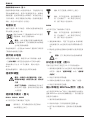
Protecting the Environment
Separate collection. This product must
not be disposed of with normal
household waste.
Should you find one day that your DeWALT product
needs replacement, or if it is of no further use to you,
do not dispose of it with household waste. Make this
product available for separate collection.
Separate collection of used products
and packaging allows materials to be
recycled and used again. Re-use of
recycled materials helps prevent
environmental pollution and reduces
the demand for raw materials.
Local regulations may provide for separate collection
of electrical products from the household, at
municipal waste sites or by the retailer when you
purchase a new product.
DeWALT provides a facility for the collection and
recycling of DeWALT products once they have
reached the end of their working life. To take
advantage of this service please return your product
to any authorised repair agent who will collect them
on our behalf.
You can check the location of your nearest
authorised repair agent by contacting your local
DeWALT office at the address indicated in this
manual. Alternatively, a list of authorised DeWALT
repair agents and full details of our after-sales
service and contacts are available on the Internet at:
www.2helpU.com.

12
D EWALT
D25413 D25414 D25415 D25430
220 220 220 220
1000 1000 1000 1000
/ 0 – 820 0 – 820 0 – 820 –
/ 0 – 4700 0 – 4700 0 – 4700 0 – 4700
4.9 4.9 4.9 –
4.9 4.9 4.9 4.9
/ /
13 / 32 / 32 13 / 32 / 32 13 / 32 / 32 –
12 12 12 12
100 100 100 –
SDS Plus
®
SDS Plus
®
SDS Plus
®
SDS Plus
®
60 60 60 60
4.2 4.3 4.3 4.0
D25413 D25414 D25415 D25430

13
2)
3) /
4)
5)
6)
7)
d)
1)
2)
3)
4)
5)
a)
1)
2)
3)
b)
1)
2)
3)
4)
5)
6)
RCD
RCD
C)
1)

14
•
•
•
•
•
•
–
–
–
– /
6)
7)
e)
a)
•
•
•
•
•
•
•

15
m. D25414 D25415
n.
o. D25430
D25413 D25414 D25415
D25430
•
1
(b) (f)
2013 XX XX
1
1
1 D25413 D25414
D25415
1
1 D25414 D25415
1
•
•
1-46
a.
b.
c. /
d.
e.
f.
g. /
h.
i. LED D25415
j. D25413 D25414
D25415
k.
l.

16
D25430
1. (e)
(d)
2.
3
12
1. (d)
2.
3. (d)
4.
SDS Plus
®
4)
SDS Plus
®
4
SDS Plus
®
1.
2. / (g)
3.
D25415 2
LED (i)
DEWALT IEC 60745
115V
DEWALT
3
1.5
30
(OFF)
3)
D25413 D25414 D25415

17
1.
2.
SDS Plus
®
3. SDS Plus
®
6)
D25414 D25415
1. (l) /
(g)
2. (m)
3.
1, 4)
(n)
1. (g)
(n)
2.
3.
4.
5. /
(g)
1)
(f)
1.
2.
3.
4)
D25413 D25414 D25415
1.
2. (k)
3. (j)
4.
5.
/ 5)
1. (RH) / (c)
2. (LH) / (c)

18
1)
1.
2.
3. (f)
4.
5.
6.
7.
1, 3)
1. (d)
2. (f)
3.
4.
5. (a)
1
6.
7.
8.
(OFF)
•
• 5 kg
•
•
7)
7
(f)
(b)
1)
1. (a)
2.
3. /
(c)
ページが読み込まれています...
ページが読み込まれています...
ページが読み込まれています...
ページが読み込まれています...
ページが読み込まれています...
ページが読み込まれています...
ページが読み込まれています...
ページが読み込まれています...
ページが読み込まれています...
ページが読み込まれています...
ページが読み込まれています...
ページが読み込まれています...
ページが読み込まれています...
ページが読み込まれています...
ページが読み込まれています...
ページが読み込まれています...
ページが読み込まれています...
ページが読み込まれています...
ページが読み込まれています...
ページが読み込まれています...
ページが読み込まれています...
ページが読み込まれています...
ページが読み込まれています...
ページが読み込まれています...
ページが読み込まれています...
ページが読み込まれています...
ページが読み込まれています...
ページが読み込まれています...
ページが読み込まれています...
ページが読み込まれています...
ページが読み込まれています...
ページが読み込まれています...
ページが読み込まれています...
ページが読み込まれています...
ページが読み込まれています...
ページが読み込まれています...
ページが読み込まれています...
ページが読み込まれています...
ページが読み込まれています...
-
 1
1
-
 2
2
-
 3
3
-
 4
4
-
 5
5
-
 6
6
-
 7
7
-
 8
8
-
 9
9
-
 10
10
-
 11
11
-
 12
12
-
 13
13
-
 14
14
-
 15
15
-
 16
16
-
 17
17
-
 18
18
-
 19
19
-
 20
20
-
 21
21
-
 22
22
-
 23
23
-
 24
24
-
 25
25
-
 26
26
-
 27
27
-
 28
28
-
 29
29
-
 30
30
-
 31
31
-
 32
32
-
 33
33
-
 34
34
-
 35
35
-
 36
36
-
 37
37
-
 38
38
-
 39
39
-
 40
40
-
 41
41
-
 42
42
-
 43
43
-
 44
44
-
 45
45
-
 46
46
-
 47
47
-
 48
48
-
 49
49
-
 50
50
-
 51
51
-
 52
52
-
 53
53
-
 54
54
-
 55
55
-
 56
56
-
 57
57
-
 58
58
-
 59
59


