Dell PowerEdge R420xr 取扱説明書

タイプ
取扱説明書
Dell PowerEdge R420xr
901D Reinforcement Kit
901D 强化套件
Kit de renforcement 901D
901D-Erweiterungssatz
901D 強化キット
901D 보완 키트
Kit de refuerzo 901D
901D Destek Kiti
Dell PowerEdge R420xr
901D Reinforcement Kit
Installation Guide
Notes, Cautions, and Warnings
NOTE: A NOTE indicates important information that helps you make better use of
your computer.
CAUTION: A CAUTION indicates either potential damage to hardware or loss of
data and tells you how to avoid the problem.
WARNING: A WARNING indicates a potential for property damage, personal
injury, or death.
____________________
Copyright © 2014 Dell Inc. All rights reserved.
This product is protected by U.S. and international copyright and intellectual property laws. Dell™
and the Dell logo are trademarks of Dell Inc. in the United States and/or other jurisdictions. All other
marks and names mentioned herein may be trademarks of their respective companies.
2014 - 10 8JK58 Rev. A01
Installation Guide 3
Introduction
This document describes the procedure for installing the components in the
901D reinforcement kit on Dell PowerEdge R420xr systems.
WARNING: Opening or removing the system cover when the system is on may
expose you to a risk of electric shock.
CAUTION: Many repairs may only be done by a certified service technician.
You should only perform troubleshooting and simple repairs as authorized in your
product documentation, or as directed by the online or telephone service and
support team. Damage due to servicing that is not authorized by Dell is not covered
by your warranty. Read and follow the safety instructions that came with the product.
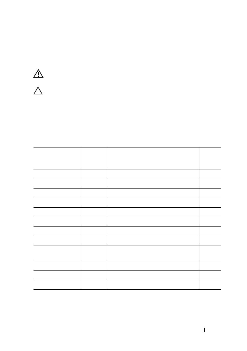
Contents of 901D Reinforcement Kit
Item No. Dell Part
Number
(DPN)
Description Quantity
Electrical insulator 0M4XF INSUL,MYLAR,PCI BRKT,R2,R420,X 1
Screw 23FYT SCR,M2.5X.45X4MM,FLH,PH,CSKT,Z 6
Screw VW2J4 SCR,4-20X3/8,TORX,TF,SS,PLST,X 1
Screw JNG28 SCR,4-40X7MM,PH,PHH,ZPS,XR 3
Bracket assembly
FYGC8 ASSY,BRKT,PCI-LOCK,R2,R420,XR 1
Plastic block TGNK5 BRKT,BLOCK,PCI-LOCK,R1,R420,XR 1
System board lock
V5PYK CLP,PLSTC,PCI-CARD,R420XR 1
PSU lock bracket
X23KY BRKT,PSU,RET,1U,R420,XR,OEM 1
PCe card support
bracket
T621V BRKT,PCI-LOCK,R1,R420,XR 1
Battery clip 5C6HG CLP,PLSTC,BATTERY,R420XR 2
Server tie wrap 6N5P9 STRAP,CBL,6,TIE-WRAP,RMVBL,XR 6
Instruction manual 8JK58 ASSEMBLY INSTRUCTION 1
4 Installation Guide
Inside the System
NOTE: The components used to illustrate the installation procedure may vary from
the actual components.
The following components inside the system will be reinforced.
Figure 1-1. Components That will be Reinforced
1 PSU 2 PERC card
3 PCIe card riser 2 4 system board lock
5 PCIe card riser 1
Installation Guide 5
Installing the PERC Battery Clip
1
Turn off the system and attached peripherals, and disconnect the system
from the electrical outlet.
2
Loosen the three captive screws on the top of the system cover.
3
Loosen the thumb screws that secure the back of the system cover to
the chassis.
4
Hold the thumb screws and slide the system cover toward the back of
the system.
5
Remove the system cover. For more information see your system Owner’s
Manual at
dell.com/poweredgemanuals
.
6
Remove the PERC card by pressing down on the two release levers at the
edge of the card to disengage the card from the connector. For more
information see the topic Integrated Storage Controller Card in your
system Owner’s Manual at
dell.com/poweredgemanuals.
7
Loosen the screw on the PERC battery clip to open the battery clip.
8
Install the PERC battery clip on the PERC battery as shown in Figure 1-1.
9
Tighten the screw to secure the PERC battery using the battery clip.
10 Install the PERC battery assembly on the system board. For more
information, see the topic Integrated Storage Controller Card in your
system Owner’s Manual at dell.com/poweredgemanuals.
6 Installation Guide
Figure 1-2. Installing the PERC Battery Clip
Replacing the System Board Lock
1
Open the system.
2
Locate the system board lock. See Figure 1-1.
3
Pressing down on the black tab, slide the existing system board lock in the
direction of the arrow as shown in Figure 1-3.
1 screw on the PERC battery clip 2 PERC battery clip (
DPN: 5C6HG)
3 PERC battery assembly 4 connector on system board
Installation Guide 7
Figure 1-3. Removing the System Board Lock
4
Press the tab on the system board lock as shown in Figure 1-4 and install it
on the system board
NOTE: The new system board lock can be identified by the square feature.
1 existing system board lock 2 tab
8 Installation Guide
Figure 1-4. Installing the New System Board Lock
Securing Full Half-Length PCIe Card on Riser 1
1
Install the full half-length PCIe card on riser 1.
2
Slide the system board lock in the direction of the arrow such that the edge
of the PCIe card is secured against the system board lock as shown in
Figure 1-5.
1 square feature 2 system board lock (DPN: V5PYK)
3 tab
Installation Guide 9
Figure 1-5. Securing Full Half-Length PCIe Card Using the System Board Lock
Securing Half-Length PCIe Card on Riser 1
NOTE: Perform this procedure for PCIe expansion cards that are shorter than
half-length PCIe expansion cards.
1
Remove PCIe riser 1 from the system board. For more information, see the
Owner’s Manual at
dell.com/poweredgemanuals
.
2
Remove the screw on PCIe riser 1.
1 system board lock (DPN: V5PYK) 2 full half-length PCIe card
3 PCIe riser 1 connector 4 PCIe riser 1
10 Installation Guide
Figure 1-6. Installing the Plastic Block on Riser 1
3
Locate the Phillips head screw and the plastic block in the
901D
reinforcement kit
.
4
Install the plastic block on riser 1 along with the riser securing tab as
shown in Figure 1-6.
5
Install the riser 1 assembly on the system board.
1 screw (DPN: VW2J4) 2 plastic block (DPN: TGNK5)
3 riser 1 4 riser securing tab
Installation Guide 11
Figure 1-7. Installing the PCIe Bracket on Riser 1
6
Install the PCIe card on riser 1.
7
Secure the card support bracket on riser 1 using the two screws as shown in
Figure 1-7.
1 PCle card support bracket (DPN: T621V) 2 screw (DPN: JNG28)
3 PCIe card 4 PCIe riser assembly
5 plastic block (DPN: TGNK5)
12 Installation Guide
Securing the PCIe Card on Riser 2
1
Locate and remove the PCIe card on riser 2.
2
Unfasten the screw on the PCIe card and install the electrical insulator
tape on the PCB as shown in Figure 1-8.
NOTE: Make sure that the hole on the tape is aligned with the hole on the
PCIe card.
3
Locate the riser 2 bracket assembly (DPN: FYGC8).
NOTE: The riser 2 metal bracket comes as an assembly. Loosen the screws
that hold the plastic bracket and the metal bracket to separate the two
components.
4
Place the plastic block on the system board adjascent to riser 2 such that
Point A is aligned with the PCIe connector as shown in Figure 1-8.
5
Install the PCIe card on riser 2.
6
Slide the plastic block with point A sliding along the PCIe riser connector,
and point B beneath the PCIe card as shown in Figure 1-8.
NOTE: The riser 2 metal bracket comes as an assembly. Loosen the screws
that hold the plastic bracket and the metal bracket to separate the two
components.
7
Align the screw holes on the metal bracket with the screw holes on the
PCIe card and the plastic bracket as shown in Figure 1-8.
NOTE: Adjust the position of the plastic bracket such that the metal bracket
screw holes are aligned with that on the plastic bracket.
8
Place riser 2 metal bracket on PCIe card and secure using a screw as shown
in Figure 1-8.
9
Secure the metal bracket to the plastic bracket using the two screws.
Installation Guide 13
Figure 1-8. Securing the Riser 2 PCIe Card
NOTE: If the PCIe card on riser 2 is PERCHT810, install a battery strap to secure it to
the PCB.
1 PCIe card riser 2 2 PCIe card riser 2 connector
3 screws on metal bracket 4 metal bracket (DPN: FYGC8)
5 screw (DPN: JNG28) 6 electrical insulator tape on PCB (DPN: 0M4XF)
7 plastic block (DPN: FYGC8)
A
B
14 Installation Guide
Installing the PSU Lock
1
Replace the system top cover.
2
Place the PSU lock against the PSU as shown in Figure 1-9.
3
Fasten the three screws on the top side on the system.
4
Fasten the three screws at the bottom of the system.
Figure 1-9. Installing the PSU Lock
1 screws (DPN: 23FYT) 2 screw hole on system top cover (3)
3 PSU lock (DPN: X23KY)
Dell PowerEdge R420xr
901D
强化套件安装指南
注、小心和警告
注:“注”表示可以帮助您更好地使用计算机的重要信息。
小心:“小心”表示可能会损坏硬件或导致数据丢失,并说明如何避免此类
问题。
警告:“警告”表示可能会导致财产损失、人身伤害甚至死亡。
____________________
Copyright © 2014 Dell Inc. 保留所有权利。
本产品受美国版权
、国际版权和知识产权法律保护。
Dell
Dell
徽标是
Dell Inc.
在美国和 /
或其他司法管辖区的商标。本文档中所述及的其它商标和产品名称可能是其各自所属公司的
商标。
2014 - 10 8JK58 Rev. A01
安装指南 17
简介
本文档介绍在 Dell PowerEdge R420xr 系统上安装 901D 强化套件中组件的
操作步骤。
警告:系统处于开启状态时打开或卸下系统护盖会使您有触电的风险。
小心多数维修只能由经认证的维修技术人员进行。您只能根据产品说明文
件中的授权,或者在联机或电话服务和支持小组的指导下,进行故障排除和
简单的维修。未经 Dell 授权的维修所造成的损坏不在保修范围之内。请阅读
并遵循产品附带的安全说明。
901D 强化套件的组成部分
项目号 Dell 部件号
(DPN)
说明 数量
电绝缘胶带
0M4XF
绝缘、胶带、 PCI 支架、 R2 R420 X
1
螺钉
23FYT
螺钉、 M2.5X.45X4MM FLH PH
CSKT Z
6
螺钉
VW2J4
螺钉、4-20X3/8TORXTFSSPLSTX
1
螺钉
JNG28
螺钉、4-40X7MMPHPHHZPSXR
3
支架组件
FYGC8
组件、支架、PCI-LOCKR2R420XR
1
塑料块
TGNK5
支架、块、 PCI 锁、 R1 R420 XR
1
系统板锁
V5PYK
CLP PLSTC PCI 卡、 R420XR
1
PSU
锁定支架
X23KY
支架、PSURET1UR420XROEM
1
PCe 卡支撑架
T621V
支架、 PCI 锁、 R1 R420 XR
1
电池固定夹
5C6HG
CLP、塑料、电池、 R420XR
2
服务器绑扎带
6N5P9
束带、CBL6绑扎带、XRRMVBLXR
6
说明手册
8JK58
组件说明
1
18 安装指南
系统内部组件
注:用于演示安装操作步骤的组件可能会与实际组件不同。
系统中的以下组件将得到强化。
1-1. 将强化的组件
1 PSU 2
PERC
3
PCIe 卡提升板 2
4
系统板锁
5
PCIe 卡提升板 1
  • Page 1 1
  • Page 2 2
  • Page 3 3
  • Page 4 4
  • Page 5 5
  • Page 6 6
  • Page 7 7
  • Page 8 8
  • Page 9 9
  • Page 10 10
  • Page 11 11
  • Page 12 12
  • Page 13 13
  • Page 14 14
  • Page 15 15
  • Page 16 16
  • Page 17 17
  • Page 18 18
  • Page 19 19
  • Page 20 20
  • Page 21 21
  • Page 22 22
  • Page 23 23
  • Page 24 24
  • Page 25 25
  • Page 26 26
  • Page 27 27
  • Page 28 28
  • Page 29 29
  • Page 30 30
  • Page 31 31
  • Page 32 32
  • Page 33 33
  • Page 34 34
  • Page 35 35
  • Page 36 36
  • Page 37 37
  • Page 38 38
  • Page 39 39
  • Page 40 40
  • Page 41 41
  • Page 42 42
  • Page 43 43
  • Page 44 44
  • Page 45 45
  • Page 46 46
  • Page 47 47
  • Page 48 48
  • Page 49 49
  • Page 50 50
  • Page 51 51
  • Page 52 52
  • Page 53 53
  • Page 54 54
  • Page 55 55
  • Page 56 56
  • Page 57 57
  • Page 58 58
  • Page 59 59
  • Page 60 60
  • Page 61 61
  • Page 62 62
  • Page 63 63
  • Page 64 64
  • Page 65 65
  • Page 66 66
  • Page 67 67
  • Page 68 68
  • Page 69 69
  • Page 70 70
  • Page 71 71
  • Page 72 72
  • Page 73 73
  • Page 74 74
  • Page 75 75
  • Page 76 76
  • Page 77 77
  • Page 78 78
  • Page 79 79
  • Page 80 80
  • Page 81 81
  • Page 82 82
  • Page 83 83
  • Page 84 84
  • Page 85 85
  • Page 86 86
  • Page 87 87
  • Page 88 88
  • Page 89 89
  • Page 90 90
  • Page 91 91
  • Page 92 92
  • Page 93 93
  • Page 94 94
  • Page 95 95
  • Page 96 96
  • Page 97 97
  • Page 98 98
  • Page 99 99
  • Page 100 100
  • Page 101 101
  • Page 102 102
  • Page 103 103
  • Page 104 104
  • Page 105 105
  • Page 106 106
  • Page 107 107
  • Page 108 108
  • Page 109 109
  • Page 110 110
  • Page 111 111
  • Page 112 112
  • Page 113 113
  • Page 114 114
  • Page 115 115
  • Page 116 116

Dell PowerEdge R420xr 取扱説明書

タイプ
取扱説明書