
Installation Manual
For models DC0041CR - 3.6 cubic foot, DC electric refrigerators.
For models DC0061CR - 7.0 cubic foot, DC electric refrigerators.
Part No. 636099A (5/30/2013)
Special Requirements for Marine Installations:
If the positive (+12/24 volts) input is grounded (by cuts in the wire insulation, incorrectly insulated components,
etc.) a voltage potential can be caused throughout the boat, which causes corrosion to form on any metal parts
that are exposed to water.
This condition can be avoided by wiring the boat so that the wiring is protected per NNMA CERTIFICATION
HANDBOOK (1987). Inspect all wiring to make sure that the insulation is not damaged and use plastic wire
clamps.
One reference for more information on corrosion is:
BOAT AND YACHT CORROSION CONTROL
by Yacht Corrosion Consultants, Inc.
2368 Eastman Ave. #6
Ventura, CA 93003
THETFORD - China
Room 1207
Coastal Building (East Block)
Hai De San Dao/ Nanshan
Shenzhen 518059/P.R.China
Telephone:+86 755 86272006/13801785859
Web Site: www.thetford.cn

Installation Manual 2
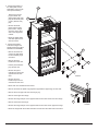
Table of Contents
Safety Awareness .....................................................................................................................................................................................2
Safety Instructions ....................................................................................................................................................................................2
Assemble the Enclosure ..........................................................................................................................................................................3
Ventilation Requirements..........................................................................................................................................................................3
Installation Options ...................................................................................................................................................................................4
Install the decorative door panel(s) ...................................................................................................................................................4
Reverse the door swing (DC0041CR models) ..................................................................................................................................5
Reverse the door swing (DC0061CR models) ..................................................................................................................................8
Connect the Drain Tube.......................................................................................................................................................................... 11
Install the Refrigerator ............................................................................................................................................................................ 11
Connect the Electrical Components .......................................................................................................................................................12
Electrical current necessary ............................................................................................................................................................12
Connect the 12 / 24 volts DC supply ..............................................................................................................................................12
Safety Instructions
Safety Awareness
Read this manual carefully and understand the contents before you install the refrigerator.
Be aware of possible safety hazards when you see the safety alert symbol on the refrigerator and in this manual. A signal word follows
the safety alert symbol and identies the danger of the hazard. Carefully read the descriptions of these signal words to fully know their
meanings. They are for your safety.
This signal word means a hazard, which if ignored, can cause dangerous personal injury, death, or much
property damage.
This signal word means a hazard, which if ignored, can cause small personal injury or much property
damage.
- The refrigerator installation must comply with local and/or national electrical codes.
- Incorrect installation, adjustment, alteration, or maintenance of this refrigerator can cause personal injury, property
damage, or both.
- Obey the instructions in the “Ventilation Requirements” section of this manual.
- Do not bypass or change the refrigerator’s electrical components or features.
- Protect all wiring from physical damage, vibration, and excessive heat.
- Do not spray liquids near electrical outlets, connections, or the refrigerator components. Many liquids are electrically
conductive and can cause a shock hazard, electrical shorts, and in some cases re.
- This appliance is intended to be used in houshold and similar applications such as recreational vehicles, boats, and
semi trucks.
CAUTION
!
WARNING
!
WARNING
!

Installation Manual 3
Assemble the Enclosure
Make sure that the enclosure is the correct size:
- For DC0041CR models - 30 7/8 inches high x 23 1/4 inches wide x 23 1/2 inches deep.
- For DC0061CR models - 52 7/8 inches high x 23 1/4 inches wide x 23 3/4 inches deep.
Make sure the oor is solid and level:
- The oor must be metal or a wood panel and extend the full width and depth of the enclosure.
- The oor must be able to support the weight of the refrigerator and its contents.
Make sure there are no adjacent heat sources such as a furnace vent, etc.
- To avoid a hazard due to instability of the appliance, it must be xed in accordance with the instructions.
- A means for disconnection from the supply mains must be incorporated in the xed wiring in accordance with the
wiring rules.
- It is necessary to allow disconnection of the appliance from the supply after installation. This disconnection may be
acheived by having the plug accessible or by incorporating a switch in the xed wiring in accordance with the wiring
rules.
- The front and rear of the refrigerator have sharp edges and corners. To prevent cuts or abrasions when working on the
refrigerator, use caution and wear cut resistant gloves.
Ventilation Requirements
This refrigerator is made for a built-in installation. Correct ventilation is necessary for the correct operation of the refrigerator and to
increase the life of the refrigerator cooling system.
Ventilation allows the natural air ow that is necessary for good refrigeration. Cooler air comes in through a lower intake vent, goes
around the refrigerator coils where it removes the excess heat from the refrigerator components, and goes out through an upper
exhaust vent. If this air ow is blocked or decreased, the refrigerator will not cool correctly. Do not install the vents into completely
enclosed areas such as closets or cabinets.
The refrigerator has built in vents at the top and at the bottom. Make sure that the ow of air through these
vents is not blocked in any way. Blockage of air through these vents can cause:
- shortened life of the refrigerator cooling unit.
- poor cooling performance of the refrigerator.
- continuous operation of the refrigerator.
- fast battery discharge.
- void of the refrigerator warranty.
CAUTION
!
CAUTION
!

Installation Manual 4
Installation Options
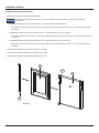
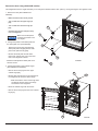
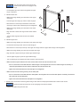
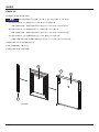
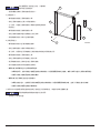
Install the decorative door panel(s):
1. Make a decorative door panel [38] (See Art02286).
The decorative panels must be 3/16 inch or less in thickness and must be within ± 1/32 inch of the following
dimensions.
- For DC0041CR models, the door panel must be 17 13/16 inches wide x 23 5/8 inches tall.
- If the door panel has a raised panel, the size of the raised part of the panel must be less than 17 7/16 inches wide x 23 5/16
inches tall.
- For DC0061CR models, the lower door panel must be 17 13/16 inches wide x 27 1/4 inches tall.
- If the door panel has a raised panel, the size of the raised part of the panel must be less than 17 7/16 inches wide x 26 15/16
inches tall.
- For DC0061CR models, the upper door panel must be 17 13/16 inches wide x 16 1/2 inches tall.
- If the door panel has a raised panel, the size of the raised part of the panel must be less than 17 7/16 inches wide 16 3/16
inches tall.
2. Pull the panel retainer [37] off the hinge side of the door [39].
3. Push the decorative door panel into the slots [157] of the door.
4. Push the panel retainer into the original position on the door.
Art02286
37
38
39
157
NOTICE

Installation Manual 5
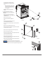
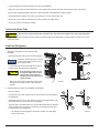
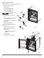
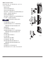
Reverse the door swing (DC0041CR models):
This refrigerator has door hinges that allow you to change the direction that the door opens by moving the hinges to the opposite corner.
1. Remove the door (See Art02281 and
Art02405):
- Make sure that the door is fully closed.
- Turn out and save the upper hinge pin
[63].
- Turn out and save the lower hinge pin
[64].
- Carefully open the door and pull it away
from the refrigerator.
Make sure that the plastic
bushings [74] remain in the
door hinges.
2. Change the position of the strike plate and
the strike plate cover (See Art02406):
- Remove the screws [41] that attach the
strike plate (with hole) [65] and the strike
plate cover (without hole) [163].
- Reverse the strike plate and the strike
plate cover and put each one on the other
side of the refrigerator cabinet.
- Attach the strike plate and strike plate cover
with the screws.
3. Change the position of the cabinet hinges
(See Art02281 and Art02405):
- Remove the screws [41] from the upper
cabinet hinge [66].
- Reverse this hinge and put on the other side of
the refrigerator as the lower cabinet hinge.
- Make sure that the center of the hinge slots
are aligned with the center of the hinge
screw holes in the refrigerator.
- Attach the cabinet hinge with the screws.
- Remove the screws [41] from the lower cabinet
hinge [67].
Art02281
41
66
41
67
74
Art02405
63
64
224
99
NOTICE

Installation Manual 6
- Put this hinge on the other side of
the refrigerator as the upper cabinet
hinge.
- Make sure that the center of the
hinge slots are aligned with the
center of the hinge screw holes in
the refrigerator.
- Attach the cabinet hinge with the
screws.
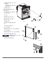
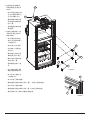
4. Change the position of the door
hinges and handle (See Art00985 and
Art02287):
- Remove and save the screws [41]
that attach the door handle [70] to the
refrigerator door.
- Remove the door handle.
- Pull the panel retainers [37]off the
door.
- Reverse the panel retainers and push
onto opposite side of the door.
- Reverse the door handle and put on the other side of
the door.
- Attach the door handle with the screws.
- Remove and save the plastic cap [42] that is opposite
the upper hinge of the door.
- Remove the screw [72] from the door hinges [73].
- Remove the upper door hinge.
- Reverse the hinge and put on the opposite side of the
door as the lower door hinge.
- Remove the lower door hinge.
- Reverse the hinge and put on the opposite side of the
door as the upper door hinge.
- Attach each of these hinges with the screws that were
removed from the other side.
You may need to pierce a hole in the door
gasket to allow the screw to engage the door hinge.
- Put the plastic cap in the hole that is opposite the upper hinge.
Art02287
41
70
37
42
37
73
73
Art02406
163
65
41
73
72
Art00985
NOTICE

Installation Manual 7
5. Install the door:
Make sure that the plastic bushings [74] remain in the door hinges.
- Set the lower door hinge onto the lower cabinet hinge and push the door closed until the door latch engages the strike plate.
- Align the holes of the lower door hinge and the lower cabinet hinge.
- Turn the lower hinge pin down through the lower door hinge into the lower cabinet hinge.
- Align the holes of the upper door hinge and the upper cabinet hinge.
- Turn the upper hinge pin up through the upper door hinge into the upper cabinet hinge.
- Make sure that the space between the door and the cabinet is the same all around the door.
- If it is not, loosen the screws that attach the cabinet hinges to the refrigerator and move the cabinet hinges as necessary to
make the space between the door and the cabinet the same all around the door.
- Tighten the screws that attach the cabinet hinges to the refrigerator.
- Make sure that the door latch goes fully into the strike plate.
- If it is not, loosen the screws that attach the strike plate to the refrigerator and move the strike plate as necessary until the door
latch goes fully into the strike plate.
- Tighten the screws that attach the strike plate to the refrigerator.
6. Seal all of the screw holes in the door gasket using a 100% silicone multi-purpose sealant that is safe for food contact:
Read and follow the instructions on the packaging of the silicone sealant.
- Pull the door gasket away from the door.
- Locate the half-moon shaped openings in the door (See Art00985).
- Apply some of the silicone sealant between the door gasket and the plastic door liner and also ll the screw hole opening.
- Push the door gasket back against the door to allow the gasket to seal against the silicone sealant.
- Smooth the silicone sealant in the screw hole opening so it is even with the door cap.
- Remove any excess silicone sealant from the door cap with a dry paper towel.
- Trim off any excess cured silicone sealant.
NOTICE
NOTICE

Installation Manual 8
Reverse the door swing (DC006CR models):
The refrigerator has door hinges that allow you to change the direction that the doors
open by moving the hinges to the opposite corner.
1. Remove the doors (See Art02288).
- Make sure that the doors are fully closed.
- Turn out and save the upper hinge pin [63].
- Turn out and save the center hinge pin caps [42].
- Open the upper door a small amount and pull the top of the upper door away from
the upper hinge of the refrigerator.
- Lift the upper door off of the center hinge pin [71].
- Turn out and save the lower hinge pin [64].
- Open the lower door a small amount and pull the bottom of the lower door away
from the lower hinge of the refrigerator.
- Pull the lower door down off of the center hinge pin.
Make sure that the plastic bushings [74] remain in the door hinges.
2. Change the position of the cabinet hinges:
- Remove the screws [41] from the upper cabinet hinge [66].
- Put this hinge on the other side of the refrigerator cabinet as the lower cabinet
hinge.
- Make sure that the center of the hinge slots are aligned with the center of the
hinge screw holes in the refrigerator.
- Attach the hinge with the screws.
- Remove the screws [41] from the lower cabinet hinge [67].
- Put this hinge on the other side of the refrigerator cabinet as the upper cabinet
hinge.
- Make sure that the center of the hinge slots are aligned with the center of the
hinge screw holes in the refrigerator.
- Attach the hinge with the screws.
- Remove the screws [41] from the center cabinet hinge [235].
- Remove the center cabinet hinge.
- Turn the screws back into the original holes and tighten the screws.
- Remove the three screws on the opposite side of the refrigerator cabinet.
- Reverse the center cabinet hinge and put it on the opposite side of the refrigerator cabinet.
- Make sure that the center of the hinge slots are aligned with the center of the hinge screw holes in the refrigerator.
- Attach the hinge with the screws.
- Turn the center hinge pin [71] out of the center cabinet hinge.
- Reverse the center hinge pin and turn it down into the top of the center cabinet hinge.
Art02288
66
74
63
42
71
235
74
42
64
74
67
41
41
41
NOTICE

Installation Manual 9
3. Change the position of
the strike plate and the
strike plate cover for both
doors (See Art02407):
- Remove the screws
[41] that attach the
strike plates (with hole)
[65] and the strike plate
covers (without hole)
[63].
- Reverse the strike
plates and the strike
plate covers and put
each one on the other
side of the refrigerator
cabinet.
- Attach the strike plates
and strike plate covers
with the screws.
4. Change the position
of the door hinges and
handle of both doors (See
Art02287 and Art00985):
- Remove and save the
screws [41] that attach
the door handle [70] to
each door.
- Remove the door
handle from each door.
- Pull the panel retainers
[37] off each door.
- Reverse the panel
retainers and push onto
opposite side of each
door.
- Reverse the door
handle and put on the
other side of each door.
- Attach each door handle with the screws.
- Remove and save the plastic cap [42] that is opposite the upper hinge of each door.
- Remove the screw [72] from each door hinge [73].
- Remove each upper door hinge.
- Reverse the hinge and put on the opposite side of each door as the lower door hinge.
- Remove each lower door hinge.
- Reverse the hinge and put on the opposite side of each door as the upper door hinge.
- Attach the hinges with the screws that were removed from the other side of each door.
65
63
Art02407
99
224
41
41
73
72
Art00985

Installation Manual 10
You may need to pierce a hole in the door
gasket to allow the screw to engage to door
hinge.
- Put the plastic cap in the hole that is opposite the upper
hinge of each door.
5. Install the lower door:
- Make sure a hinge bushing is in the bottom of the upper
door hinge.
- Push the upper door hinge up onto the center hinge pin.
- Allow the door to close and put the bottom of the lower
door hinge onto the lower cabinet hinge of the refrigerator.
- Make sure a hinge bushing is in the bottom of the lower
door hinge.
- Align the holes in lower door hinge and the lower cabinet
hinge.
- Turn the lower hinge pin down into the lower cabinet
hinge.
6. Install the upper door:
- Make sure a hinge bushing is in the bottom of the lower door hinge.
- Put the lower door hinge down onto the center hinge pin.
- Allow the door to close and put the top of the upper door hinge under the upper cabinet hinge of the refrigerator.
- Make sure a hinge bushing is in the top of the upper door hinge.
- Align the holes in upper door hinge and the upper cabinet hinge.
- Turn the upper hinge pin up into the upper cabinet hinge.
- Turn a center hinge pin cap back onto each end of the center hinge pin.
- Make sure that the space between each door and the cabinet is the same all around each door.
- If it is not, loosen the screws that attach the cabinet hinges to the refrigerator and move the cabinet hinges as necessary to
make the space between the door and the cabinet the same all around the door.
- Tighten the screws that attach the cabinet hinges to the refrigerator.
- Make sure that each door latch goes fully into the strike plate.
- If it is not, loosen the screws that attach the strike plate to the refrigerator and move the strike plate as necessary until the door
latch goes fully into the strike plate.
- Tighten the screws that attach the strike plate to the refrigerator.
7. Seal all of the screw holes in the door gasket using a 100% silicone multi-purpose sealant that is safe for food contact:
Read and follow the instructions on the packaging of the silicone sealant.
- Pull the door gasket away from the door.
Art02287
41
70
37
42
37
73
73
NOTICE
NOTICE

Installation Manual 11
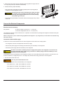
Install the Refrigerator
1. Fasten the refrigerator into the enclosure (See
Art02289):
- Push the refrigerator fully into the enclosure opening.
DC0041CR models have four mounting
screws and DC0061CR models have
six mounting screws.
- Put the mounting screws [41] through the mounting
ange [156] on both sides of the refrigerator.
If the mounting screws are not
through the upper hole of each
pair of holes in the mounting
anges, the side trim pieces will
not t correctly.
- Make sure the mounting screws are through upper
hole [121] of each pair of holes in the mounting
anges.
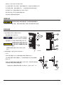
2. Install the side trim pieces (See Art02290 and Art02291):
- Open the door(s).
- Push the top only of each side trim piece [127] onto the metal frame [261] of
the refrigerator.
- While holding the top only of each side trim piece onto the metal frame, push
each side trim piece up and under the top grill [262].
- Align the hinges, the strike plate cover, and the strike plate with the openings
in the side trim pieces and push the remainder of each side trim piece onto
the metal frame of the refrigerator.
- The side trim should engage the metal frame and the inner tabs [263]
with a “snap” sound.
Connect the Drain Tube
If you do not connect the drain tube to another tube, the result will be water at the rear of the refrigerator.
1. Attach the drain tube to another tube which allows the defrost water of the refrigerator to correctly drain to a sump or to an area
outside the vehicle.
Art02290
262
261
127
263
Art02291
261
127
263
261
127
263
41
156
121
Art02289
- Locate the half-moon shaped openings in the door (See Art00985).
- Apply some of the silicone sealant between the door gasket and the plastic door liner and also ll the screw hole opening.
- Push the door gasket back against the door to allow the gasket to seal against the silicone sealant.
- Smooth the silicone sealant in the screw hole opening so it is even with the door cap.
- Remove any excess silicone sealant from the door cap with a dry paper towel.
- Trim off any excess cured silicone sealant.
CAUTION
!
CAUTION
!
NOTICE

Installation Manual 12
Connect the Electrical Components
Electrical current necessary:
DC Operation - 12 volts DC voltage (10.9 volts min. - 17 volts max.)
- 24 volts DC voltage (23.8 volts min. - 31.5 volts max.)
This refrigerator operates on a DC electrical source. Operation out of these limits may damage the refrigerator’s electrical circuit parts
and will void the warranty.
Make no changes to any of the electrical wiring supplied with the refrigerator. Any changes that you would make to the electrical wiring
will void the warranty.
Connect the 12/24 volts DC supply:
To reduce the risk of electrical interference from other DC appliances and induction from voltage spikes:
- The refrigerator must have an independent 12/24 volt DC supply.
- Route the DC power supply wires including the fuses directly from the battery to the refrigerator.
- Twist the DC power supply wires from the battery to the refrigerator.
Do not use a converter or a battery charger to supply the DC power to the refrigerator. These devices do
not supply ltered DC power. When using a converter or a battery charger, make sure a battery is in-line
between them and the refrigerator.
As the distance from the vehicle battery to the refrigerator increases, the correct AWG wire size also increases. If the wire size is too
small for the distance, a voltage drop occurs. The voltage drop decreases the cooling performance of the refrigerator.
1. Find the minimum wire size to use:
Use only the recommended wire size.
- Measure the distance from the vehicle battery to the refrigerator:
- If the distance is 0 - 12 feet, use #12 AWG min. wire size.
- If the distance is 12-20 feet, use #10 AWG min. wire size.
- If the distance is over 20 feet, use #8 AWG min. wire size.
3. Put the hinge hole covers onto the refrigerator cabinet opposite the hinges and over
the empty hinge holes (See Art02283 and Art02285).
4. Install the bottom grill (See Art02292):
- Align the mounting clips [196] of the bottom grill [264] with the openings [265] in
the bottom rail of the refrigerator cabinet.
Carefully push both ends of the bottom grill equally to engage
the mounting clips in the bottom rail at the same time. If the
mounting clips engage the bottom rail one at a time, damage
to the bottom grill can result.
- Push the bottom grill toward the lower frame until the mounting clips “snap” into the
bottom rail.
Art02292
265
264
196
CAUTION
!
CAUTION
!
WARNING
!

Installation Manual 13
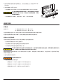
2. To protect the DC power supply wiring, install a 15 amp fuse or circuit breaker in the positive (+) DC power supply wire as close to
the battery as possible.
- There is a 15 amp automotive fuse in the DC circuit at the refrigerator power supply leads.
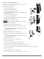
3. Connect the DC power supply wires (See Art02282 and Art02283):
If the DC power supply leads are attached incorrectly, the refrigerator will not operate.
- Connect the positive (+) DC power supply lead to the red wire [99] of the refrigerator.
- Connect the negative (-) DC power supply lead to the black wire [224] of the refrigerator.
- Make sure that:
- Each DC power supply lead is attached to the correct polarity wire of the refrigerator power supply.
- The chassis or the vehicle frame is not used as one of the conductors.
- The DC power supply wires including the fuses are routed directly from the battery to the refrigerator.
- The wire connections must be clean, tight and free of corrosion. If any of these items are not correct:
- A voltage drop to the refrigerator will occur.
- The voltage drop will decrease the cooling performance of the refrigerator.
Disconnect the positive (+) DC power supply wire from the battery before you do a “fast charge” of
the battery. Failure to disconnect the positive (+) power supply wire from the battery during a “fast
charge” can cause damage to the refrigerator or other DC appliances.
CAUTION
!
NOTICE

Installation Manual 14

DC0041CR - 3.6
DC0061CR - 7.0
636099A 2013 5 30
+12/24
NNMA (1987)
BOAT AND YACHT CORROSION CONTROL
Yacht Corrosion Consultants, Inc.
2368 Eastman Ave.#6
Ventura, CA 93003
THETFORD -
518059
1207
+86 755 86272006/13801785859
www.thetford.cn

2
...................................................................................................................................................................................................2
................................................................................................................................................................................................
...2
..................................................................................................................................................................................................3
..............................................................................................................................................................................................
.....3
...................................................................................................................................................................................................4
.....................................................................................................................................................................................4
DC0041CR ......................................................................................................................................................5
DC0061CR ......................................................................................................................................................8
.....................................................
.........................................................................................................................................11
..............................................................................................................................................................................................11
........................................................
..................................................................................................................................12
..........................................................................................................................................................................................12
12 / 24 ......................................................
...............................................................................................................12
- /
- /
-
-
-
-
-

3
- DC0041CR - 30 7/8 x 23 1/4 x 23 1/2
- DC0061CR - 52 7/8 x 23 1/4 x 23 3/4
-
-
-
-
-
-
-
-
-
-
-

4
1. [38] 02286
3/16 1/32
- DC0041CR 17 13/16 x 23 5/8
- 17 7/16 x 23 5/16
- DC0061CR 17 13/16 x 27 1/4
- 17 7/16 x 26 15/16
- DC0061CR 17 13/16 x 16 1/2
- 17 7/16 x 16 3/16
2.
[37] [39]
3. [157]
4.
Art02286
37
38
39
157

5
DC0041CR
1. 02281 02405
-
- [63]
- [64]
-
[74]
2.
02406
- [65]
[163] [41]
-
-
3. 02281
02405
- [66] [41]
-
-
-
- [67] [41]
Art02281
41
66
41
67
74
Art02405
63
64
224
99

6
-
-
-
4.
00985 02287
- [70]
[41]
-
- [37]
-
-
-
-
[42]
- [73] [72]
-
-
-
-
-
-
Art02287
41
70
37
42
37
73
73
Art02406
163
65
41
73
72
Art00985
ページが読み込まれています...
ページが読み込まれています...
ページが読み込まれています...
ページが読み込まれています...
ページが読み込まれています...
ページが読み込まれています...
ページが読み込まれています...
ページが読み込まれています...
-
 1
1
-
 2
2
-
 3
3
-
 4
4
-
 5
5
-
 6
6
-
 7
7
-
 8
8
-
 9
9
-
 10
10
-
 11
11
-
 12
12
-
 13
13
-
 14
14
-
 15
15
-
 16
16
-
 17
17
-
 18
18
-
 19
19
-
 20
20
-
 21
21
-
 22
22
-
 23
23
-
 24
24
-
 25
25
-
 26
26
-
 27
27
-
 28
28


他の言語で
その他のドキュメント
-
Samsung RL38T775CSR ユーザーマニュアル
-
Samsung RB33R8899SR/SH ユーザーマニュアル
-
Samsung RB34K6252SS/SH ユーザーマニュアル
-
-
Samsung RS21HNLMR ユーザーマニュアル
-
Electrolux ENN2754AOW ユーザーマニュアル
-
Electrolux ENN2853COW ユーザーマニュアル
-
-
 Küppersbusch IK32622TCN ユーザーマニュアル
-
Samsung RH60H90203L ユーザーマニュアル
