Dell PowerEdge 2800 ユーザーガイド

タイプ
ユーザーガイド
www.dell.com | support.dell.com
Dell™ Systems
Installing the SCSI Backplane
Daughter Card
安装 SCSI 背板子卡
Installation de la carte fille
de fond de panier SCSI
Installieren der SCSI-Rückwandplatinen-
Tochterkarte
SCSI バックプレーンドータ
カードの取り付け
SCSI 후면판 보조 카드 설치
Instalación de la tarjeta secundaria
de plano posterior SCSI
www.dell.com | support.dell.com
Dell™ Systems
Installing the SCSI Backplane
Daughter Card
Notes, Notices, and Cautions
NOTE: A NOTE indicates important information that helps you make better use of your computer.
NOTICE: A NOTICE indicates either potential damage to hardware or loss of data and tells you how to avoid
the problem.
CAUTION: A CAUTION indicates a potential for property damage, personal injury, or death.
____________________
Information in this document is subject to change without notice.
© 2004 Dell Inc. All rights reserved.
Reproduction in any manner whatsoever without the written permission of Dell Inc. is strictly forbidden.
Trademarks used in this text: Dell, the DELL logo, and PowerEdge are trademarks of Dell Inc.
Other trademarks and trade names may be used in this document to refer to either the entities claiming the marks and names or their products.
Dell Inc. disclaims any proprietary interest in trademarks and trade names other than its own.
July 2004 P/N F6589 Rev. A00
Installing the SCSI Backplane Daughter Card 1-3
This document provides information about how to configure the split SCSI backplane in your
Dell™ PowerEdge™ 2800 or 2850 system by installing a backplane daughter card. In a split
backplane configuration, the hard-drives are arranged in two separate groups of drives.
CAUTION: Only trained service technicians are authorized to remove the system cover and access any
of the components inside the system. See your Product Information Guide for complete information
about safety precautions, working inside the computer, and protecting against electrostatic discharge.
NOTE: See your Installation and Troubleshooting Guide for detailed instructions on removing
or replacing components.
Installing the SCSI Backplane Daughter Card
in a PowerEdge 2800 System
1
Remove the bezel (if applicable).
2
Unpack the SCSI backplane daughter card kit.
3
Turn off the system, including any attached peripherals, and disconnect the system from
the electrical outlet.
4
Open the system.
5
Slide the drive tray to the maintenance position.
a
Use a #2 Phillips screwdriver to loosen the captive screw that secures the drive tray
release handle to the chassis.
b
Rotate the drive tray release lever toward the front of the system.
c
Grasp both sides of the front panel and slide the drive tray forwards until the tray is in
the maintenance position.
6
Hold the daughter card by its edges with the card connector facing the SCSI backplane board.
7
Insert the card connector into the daughter card connector on the SCSI backplane board.
Ensure that the standoffs on the daughter card are fully seated into the SCSI backplane
board. See Figure 1-1.
1-4 Installing the SCSI Backplane Daughter Card
www.dell.com | support.dell.com
Figure 1-1. Installing the SCSI Daughter Card
8
To use the optional integrated ROMB controller in a split 2 x 4 backplane configuration:
a
Connect channel A on the riser card to SCSIA on the SCSI backplane. This channel
controls the boot drive (drive 0) and drives 1, 2, and 3.
b
Connect SCSI channel B on the riser card to connector SCSIB on the SCSI backplane.
This channel controls drives 4, 5, 8, and 9.
To use an optional RAID controller card in a split 2 x 4 backplane configuration:
a
Connect SCSI channel A (channel 0) on the controller card to connector SCSIA on
the SCSI backplane. This channel controls the boot drive (drive 0) and drives 1, 2, and 3.
b
Connect SCSI channel B (channel 1) on the controller card to connector SCSIB on
the SCSI backplane. This channel controls drives 4, 5, 8, and 9.
9
Slide the drive tray back into the operating position.
a
Grasp both sides of the front panel and slide the drive tray backwards until the tray is
in the operating position.
b
Rotate the drive tray release lever toward the back of the system.
c
Use a #2 Phillips screwdriver to tighten the captive screw that secures the drive tray
release handle to the chassis.
10
Close the system.
11
Reconnect the system to its electrical outlet and turn the system on, including any attached
peripherals.
12
Enter System Setup to ensure that the RAID or SCSI controller card is configured correctly.
See your system’s
User’s Guide
for more information.
13
Replace the bezel (if applicable).
SCSI daughter card
SCSI backplane board
standoffs (2)
Installing the SCSI Backplane Daughter Card 1-5
Installing the SCSI Backplane Daughter Card
in a PowerEdge 2850 System
1
Unpack the SCSI backplane board daughter card kit.
2
Turn off the system, including any attached peripherals, and disconnect the system from
the electrical outlet.
3
Remove the bezel (if applicable).
4
Open the system.
5
Grasp the plastic tab on the back of the control panel cable and pull the cable connector away
from the backplane connector. See Figure 1-2.
NOTE: If you pull on the control panel cable harness, you may damage the harness.
The SCSI backplane daughter card connector and card guide are located in the compartment
below the control panel cable.
Figure 1-2. Installing a SCSI Backplane Daughter Card
SCSI daughter card
SCSI backplane
retention lever
SCSI daughter card guide
retention peg
on card
control panel cable
SCSI daughter card
backplane connector
control-panel connector on backplane
1-6 Installing the SCSI Backplane Daughter Card
www.dell.com | support.dell.com
6
The daughter card fits between the sides of the card guide. To install the daughter card in
the card guide and to connect it to the backplane connector:
a
Ensure that the retention lever is in the open position.
b
Hold the daughter card by its edges with the card connector facing the SCSI backplane
and the retention peg facing the retention lever. See Figure 1-2.
c
Lower the card into the card guide.
d
Close the retention lever to slide the daughter card into the SCSI backplane connector
and lock the card into place. See Figure 1-2.
7
Rotate the drive bay retraction bar toward the front of the system. See Figure 1-3.
Figure 1-3. Drive Bay Retraction Bar
8
Reconnect the control panel cable to its backplane connector. See Figure 1-2.
9
To use the optional integrated ROMB controller in a split backplane configuration:
a
Connect channel A on the riser card to SCSIA on the SCSI backplane. This channel
controls the boot drive (drive 0) and drive 1.
b
Connect SCSI channel B on the riser card to connector SCSIB on the SCSI backplane.
This channel controls drives 2 through 5.
drive bay retraction bar
Installing the SCSI Backplane Daughter Card 1-7
To use the optional RAID controller card in a split backplane configuration:
a
Connect SCSI channel A (channel 0) on the controller card to connector SCSIA on
the SCSI backplane. This channel controls the boot drive (drive 0) and drive 1.
b
Connect SCSI channel B (channel 1) on the controller card to connector SCSIB on
the SCSI backplane. This channel controls drives 2 through 5.
NOTE: If a cable is connected to the SCSIB backplane connector, the SCSI backplane daughter
card must be installed to activate the 2/4 split backplane configuration. Otherwise, the system will
display an error message.
10
Rotate the drive bay retraction bar toward the back of the system.
11
Close the system.
12
Enter System Setup to ensure that the RAID or SCSI controller card is configured correctly.
See your system’s
User’s Guide
for more information.
13
Replace the bezel (if applicable).
1-8 Installing the SCSI Backplane Daughter Card
www.dell.com | support.dell.com
Dell™ 系统
安装 SCSI 背板子卡
注、注意和警告
注:
注表示可以帮助您更好地使用计算机的重要信息。
注意:
注意表示可能会损坏硬件或导致数据丢失,并告诉您如何避免此类问题。
警告:
警告表示存在可能导致财产损失、人身伤害或死亡的潜在危险。
____________________
本文中的信息如有更改,恕不另行通知。
© 2004 Dell Inc.
。保留所有权利。
未经
Dell Inc.
书面许可,不得以任何方式进行复制。
本文件中使用的商标:
Dell
DELL
徽标和
PowerEdge
Dell Inc.
的商标。
本文件中述及的其它商标和产品名称是指拥有相应商标和名称的公司或其制造的产品。
Dell Inc.
对本公司的商标和产品名称之外的其它商标和产品名称不拥有任何专有权。
2004
7
P/N F6589 Rev. A00
安装 SCSI 背板子卡 2-3
本文档提供了如何在
Dell™ PowerEdge™ 2800
2850
系统中通过安装背板子卡来配置分割式
SCSI
背板的信息。在分割式背板配置中,硬盘驱动器分为两个不同的驱动器组。
警告:
只有经过培训的维修技术人员才能卸下主机盖并拆装系统内部的任何组件。有关安全预
防措施、拆装计算机内部组件以及防止静电释放的完整信息,请参阅 《产品信息指南》
注:
有关卸下或装回组件的详情,请参阅 《安装与故障排除指南》
PowerEdge 2800
系统中安装
SCSI
背板子卡
1
如果需要,请卸下挡板。
2
拆开
SCSI
背板子卡套件的包装。
3
关闭系统电源(包括连接的任何外围设备)然后断开系统与电源插座的连接。
4
打开系统外壳。
5
将驱动器托架滑动到维护位置。
a
使用
2
号梅花槽螺丝刀,松开将驱动器托架释放手柄固定到机箱的固定螺钉。
b
朝系统的正面转动驱动器托架释放拉杆。
c
抓住前面板的两端,将驱动器托架向前滑动,直到托架处于维护位置。
6
抓住子卡边缘,卡连接器朝向
SCSI
背板。
7
将卡连接器插入
SCSI
背板上的子卡连接器。确保子卡上的定位器在
SCSI
背板上完全就
位。请参阅图
2-1
2-1.
安装
SCSI
子卡
SCSI 子卡
SCSI 背板
定位器2
2-4 安装 SCSI 背板子卡
www.dell.com | support.dell.com
8
2 x 4
分割式背板配置中使用可选集成
ROMB
控制器:
a
将提升卡上的通道
A
连接到
SCSI
背板上的
SCSIA
此通道控制引导驱动器
(驱动器
0
)和
1
2
3
b
将提升卡上的
SCSI
通道
B
连接到
SCSI
背板上的
SCSIB
连接器。此通道控制驱动器
4
5
8
9
2 x 4
分割式背板配置中使用可选
RAID
控制器卡:
a
将控制器卡上的
SCSI
通道
A
(通道
0
连接到
SCSI
背板上的
SCSIA
连接器。
此通道控制引导驱动器(驱动器
0
和驱动器
1
2
3
b
将控制器卡上的
SCSI
通道
B
(通道
1
连接到
SCSI
背板上的
SCSIB
连接器。
此通道控制驱动器
4
5
8
9
9
将驱动器托架向后滑动到操作位置。
a
抓住前面板的两端,将驱动器托架向后滑动,直到托架处于操作位置。
b
朝系统的背面转动驱动器托架释放拉杆。
c
使用
2
号梅花槽螺丝刀,拧紧固定驱动器托架释放手柄和机箱的固定螺钉。
10
合上系统外壳。
11
将系统(包括连接的任何外围设备)重新连接至电源插座,然后开机。
12
输入系统设置,确保
RAID
SCSI
控制器卡配置正确无误。有关详情,请参阅系统的
《用户指南》
13
如果需要,请装回挡板。
PowerEdge 2850
系统中安装
SCSI
背板子卡
1
打开
SCSI
背板子卡套件的包装。
2
关闭系统电源(包括连接的任何外围设备)然后断开系统与电源插座的连接。
3
如果需要,请卸下挡板。
4
打开系统外壳。
5
抓住控制面板电缆后端的塑料卡舌,将电缆连接器从背板连接器上拉开。请参阅图
2-2
注:
如果拉扯控制面板电缆导线,则可能会损坏导线。
SCSI
背板子卡连接器和插卡导向器位于控制面板电缆下面的盒中。
安装 SCSI 背板子卡 2-5
2-2.
安装
SCSI
背板子卡
6
子卡适合于安装在插卡导向器两侧之间的位置。将子卡安装在插卡导向器中并将其连接
到背板连接器:
a
确保固位拉杆处于打开位置。
b
抓住子卡边缘,卡连接器朝向
SCSI
背板,固定连接销朝向固位拉杆。请参阅图
2-2
c
将插卡向下放入插卡导向器。
d
合上固位拉杆,使子卡滑入
SCSI
背板连接器并锁定到位。请参阅图
2-2
7
朝系统的正面转动驱动器托架收缩杆。请参阅图
2-3
SCSI 子卡
SCSI 背板
固位拉杆
SCSI 子卡导向器
卡上的固定连接销
控制面板电缆
SCSI 子卡背板连接器
背板上的控制面板连接器
2-6 安装 SCSI 背板子卡
www.dell.com | support.dell.com
2-3.
驱动器托架收缩杆
8
将控制面板电缆重新连接到背板连接器。请参阅图
2-2
9
在分割式背板配置中使用可选集成
ROMB
控制器:
a
将提升卡上的通道
A
连接到
SCSI
背板上的
SCSIA
此通道控制引导驱动器
(驱动器
0
)和
1
b
将提升卡上的
SCSI
通道
B
连接到
SCSI
背板上的
SCSIB
连接器。此通道控制驱动器
2
5
在分割式背板配置中使用可选
RAID
控制器卡:
a
将控制器卡上的
SCSI
通道
A
(通道
0
连接到
SCSI
背板上的
SCSIA
连接器。
此通道控制引导驱动器(驱动器
0
和驱动器
1
b
将控制器卡上的
SCSI
通道
B
(通道
1
连接到
SCSI
背板上的
SCSIB
连接器。
此通道控制驱动器
2
5
注:
如果已将电缆连接至 SCSIB 背板连接器,则必须安装 SCSI 背板子卡,才能激活 2/4
割式背板配置。否则,系统将显示错误信息。
10
朝系统的背面转动驱动器托架收缩杆。
11
合上系统外壳。
12
输入系统设置,确保
RAID
SCSI
控制器卡配置正确无误。有关详情,请参阅系统的
《用户指南》
13
如果需要,请装回挡板。
驱动器托架收缩杆
www.dell.com | support.dell.com
Systèmes Dell™
Installation de la carte fille
de fond de panier SCSI
Remarques, avis et précautions
REMARQUE : une REMARQUE indique des informations importantes qui peuvent vous aider à mieux utiliser
l'ordinateur.
AVIS : un AVIS vous avertit d'un risque de dommage matériel ou de perte de données et vous indique comment éviter
le problème.
PRÉCAUTION : une PRÉCAUTION indique un risque potentiel d'endommagement du matériel, de blessure corporelle
ou de mort.
____________________
Les informations contenues dans ce document peuvent être modifiées sans préavis.
© 2004 Dell Inc. Tous droits réservés.
La reproduction de ce document de quelque manière que ce soit sans l'autorisation écrite de Dell Inc. est strictement interdite.
Marques utilisées dans ce document : Dell, le logo DELL et PowerEdge sont des marques de Dell Inc.
Tous les autres noms de marques et marques commerciales utilisés dans ce document se rapportent aux sociétés propriétaires des marques et
des noms de ces produits. Dell Inc. décline tout intérêt dans l'utilisation des marques déposées et des noms de marques ne lui appartenant pas.
Juillet 2004 P/N F6589 Rev. A00
Installation de la carte fille de fond de panier SCSI 3-3
Le présent document explique comment configurer un fond de panier SCSI partagé sur
un système Dell™ PowerEdge™ 2800 ou 2850 en installant une carte fille de fond de panier.
Cette configuration permet de diviser les disques durs en deux groupes séparés.
PRÉCAUTION : seuls les techniciens de maintenance qualifiés sont habilités à retirer le capot du
système et à accéder aux composants du système. Consultez le Guide d'information sur le produit
pour obtenir des informations détaillées sur les consignes de sécurité, les interventions dans
l'ordinateur et la protection contre les décharges électrostatiques.
REMARQUE : consultez le Guide d'installation et de dépannage pour obtenir des instructions détaillées
sur le retrait ou le remplacement de composants.
Installation de la carte fille de fond de panier SCSI
dans un système PowerEdge 2800
1
Retirez le cadre, si nécessaire.
2
Retirez le kit de la carte fille de fond de panier SCSI de son emballage.
3
Éteignez le système et les périphériques connectés, puis débranchez-le de la prise de courant.
4
Ouvrez le système.
5
Faites glisser le plateau des lecteurs pour le placer en position de maintenance.
a
À l'aide d'un tournevis cruciforme n°2, desserrez la vis imperdable qui fixe la poignée
de dégagement du plateau au châssis.
b
Faites pivoter le levier de dégagement du plateau vers l'avant du système.
c
Saisissez les deux côtés du panneau avant et faites glisser le plateau vers l'avant jusqu'à ce
qu'il soit en position de maintenance.
6
Tenez la carte fille par les bords, son connecteur faisant face à la carte de fond de panier SCSI.
7
Insérez le connecteur de la carte dans le connecteur de carte fille du fond de panier SCSI.
Vérifiez que les picots de la carte fille sont engagés à fond dans la carte de fond de panier
SCSI. Voir la figure 3-1.
3-4 Installation de la carte fille de fond de panier SCSI
www.dell.com | support.dell.com
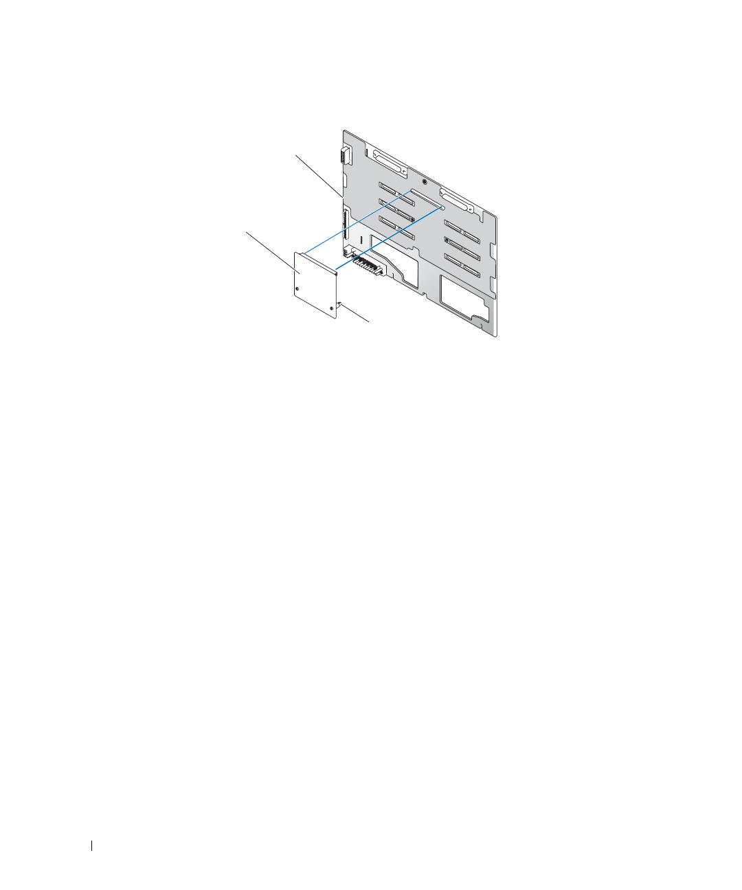
Figure 3-1. Installation de la carte fille SCSI
8
Pour utiliser le contrôleur ROMB intégré en option avec un fond de panier 2x4 partagé :
a
Connectez le canal A de la carte de montage au connecteur SCSIA du fond de panier
SCSI. Ce canal contrôle le lecteur d'amorçage (lecteur 0), ainsi que les lecteurs 1, 2 et 3.
b
Connectez le canal SCSI B de la carte de montage au connecteur SCSIB du fond de
panier SCSI. Ce canal contrôle les lecteurs 4, 5, 8 et 9.
Pour utiliser une carte contrôleur RAID intégrée en option avec un fond de panier 2x4 partagé :
a
Connectez le canal SCSI A (canal 0) de la carte contrôleur au connecteur SCSIA du fond
de panier SCSI. Ce canal contrôle le lecteur d'amorçage (lecteur 0), ainsi que les
lecteurs 1, 2 et 3.
b
Connectez le canal SCSI B (canal 1) de la carte contrôleur au connecteur SCSIB du fond
de panier SCSI. Ce canal contrôle les lecteurs 4, 5, 8 et 9.
9
Poussez le plateau des lecteurs pour le remettre en position de fonctionnement.
a
Saisissez les deux côtés du panneau avant et faites glisser le plateau vers l'arrière
du système jusqu'à ce qu'il soit en position de fonctionnement.
b
Faites pivoter le levier de dégagement du plateau vers l'arrière du système.
c
À l'aide d'un tournevis cruciforme n°2, resserrez la vis imperdable qui fixe la poignée
de dégagement du plateau au châssis.
10
Refermez le système.
11
Rebranchez le système sur la prise de courant et allumez-le, ainsi que tous les périphériques
connectés.
12
Accédez au programme de configuration du système et vérifiez que la carte contrôleur RAID
ou SCSI est correctement configurée. Consultez le
Guide d'utilisation
pour plus
d'informations.
13
Remettez le cadre en place, si nécessaire.
Carte fille SCSI
Carte de fond de panier SCSI
Picots (2)
  • Page 1 1
  • Page 2 2
  • Page 3 3
  • Page 4 4
  • Page 5 5
  • Page 6 6
  • Page 7 7
  • Page 8 8
  • Page 9 9
  • Page 10 10
  • Page 11 11
  • Page 12 12
  • Page 13 13
  • Page 14 14
  • Page 15 15
  • Page 16 16
  • Page 17 17
  • Page 18 18
  • Page 19 19
  • Page 20 20
  • Page 21 21
  • Page 22 22
  • Page 23 23
  • Page 24 24
  • Page 25 25
  • Page 26 26
  • Page 27 27
  • Page 28 28
  • Page 29 29
  • Page 30 30
  • Page 31 31
  • Page 32 32
  • Page 33 33
  • Page 34 34
  • Page 35 35
  • Page 36 36
  • Page 37 37
  • Page 38 38
  • Page 39 39
  • Page 40 40
  • Page 41 41
  • Page 42 42
  • Page 43 43
  • Page 44 44
  • Page 45 45
  • Page 46 46
  • Page 47 47
  • Page 48 48
  • Page 49 49
  • Page 50 50
  • Page 51 51
  • Page 52 52
  • Page 53 53
  • Page 54 54

Dell PowerEdge 2800 ユーザーガイド

タイプ
ユーザーガイド