
MonCaso 972 series
Product Guide
ENGLISH
Please read this manual carefully before system installations.

2 ENGLISH
MonCaso 972 series product guide
Manual Rev: 2.0
Release Date: November. 2008
Copyright ⓒ 2008 Moneual Inc. All Rights Reserved.
No parts of this manual, including the products and software describe in it, may be reproduced,
transmitted, transcribed, and stored in retrieval system, or translated into any language in any
form or by any means, except documentation kept by the purchaser for backup purpose, without
the express written permission of Moneual Lab (Moneual).
Product warranty or service will not extended if: (1) the product is repaired, modified or altered,
unless such repair, modification or alteration is authorized in writing by Moneual; or (2) the serial
number of the product is defaced or missing.
Moneual provides this manual "as is" without warranty of any kind, either express or implied,
including but not limited to the implied warranties or conditions of merchantability or fitness for a
particular purpose. In no event shall Moneual, its directors, officers, employees or agents be liable
for any indirect, special, incidental, or consequential damages (including damages for loss of
profits, loss of business, loss of use or data, interruption of business and the like), even if Moneual
has been advised of the possibility of such damages arising from any defect or error in this
manual or product.
Specifications and information contained in this manual are furnished for informational use only,
and are subject to change at any time without notice, and should not be construed as a
commitment by Moneual. Moneual assumes no responsibility or liability for any errors or
inaccuracies that may appear in this manual, including the products and software described in it.
Products and corporate names appearing in this manual may or may not be registered trademarks
or copyrights of their respective companies, and are used only for identification or explanation and
to the owners' benefit, without intent to infringe.
Revision History
Revision
Date
V1.0
January. 2008
V1.1e
V2.0
July. 2008
Novemver.2008

ENGLISH 3
Contents
Safety information .......................................................................................................... 5
Drawing of Dismantlement ............................................................................................. 6
Package Contents .......................................................................................................... 7
Specification of Product .................................................................................................. 8
Chapter 1. Introduction ................................................................................... 9
1-1. Introduction ........................................................................................................... 10
1-2. Front panel ............................................................................................................ 10
1-3. Rear panel ............................................................................................................. 12
Chapter 2. Installation Guide ....................................................................... 13
2-1. Before You Begin .................................................................................................. 14
2-2. Opening the Case ................................................................................................. 15
2-3. Installing HDD ....................................................................................................... 16
2-4. Installing ODD ....................................................................................................... 17
2-5. Installing Motherboard ........................................................................................... 18
2-6. Installing Power Supply Unit .................................................................................. 19
2-7. Cable Connection .................................................................................................. 20
2-8. Power S.W and LED Connection .......................................................................... 20
2-9. iMON LCD Connection .......................................................................................... 21
2-10. Front I/O& Card Reader Connection ................................................................... 22
2-11. RGB Terminal Connection .................................................................................. 23
2-12. Attaching ODD Bezel .......................................................................................... 24
2-13. Installing the wireless keyboard .......................................................................... 25
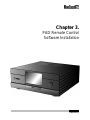
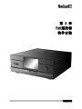
Chapter 3. PAD Remote Control Software Installation ........................... 27
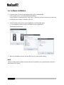
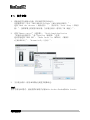
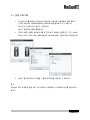
3-1. Software Installation .............................................................................................. 28
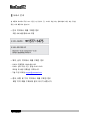
Service Notice...............................................................................................29

4 ENGLISH

ENGLISH 5
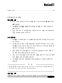
▪ Safety information
Electrical safety
1. To prevent electrical shock hazard, disconnect the power cable from the electrical outlet
before relocating the system.
2. When adding or removing devices to or from the system, ensure that the power cables
for the devices are unplugged before the signal cables are connected.
3. If the power supply is broken, do not try to fix it by yourself. Contact a qualified service
technician or your retailer.
Operation safety
1. Before installing devices into the system, carefully read all the documentation that
came with the package.
2. Before using the product, make sure all cables are correctly connected and the power
cables are not damaged. If you detect any damage, contact your dealer immediately.
3. To avoid short circuits, keep paper clips, screws, and staples away from connectors,
slots, sockets and circuitry.
4. Avoid dust, humidity, and temperature extremes. Don not place the product in any area
where it may become wet. Place the product on a stable surface.
5. If you encounter technical problems with the product, contact a qualified service
technician or your retailer.
Moneual Inc is not responsible for any damages due to external causes, including but not
limited to, improper use, problems with electrical power, accident, neglect, alteration, repair,
improper installation, or improper testing.
Disclaimer

6 ENGLISH
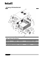
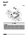
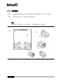
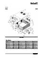
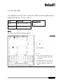
▪ Drawing of Dismantlement
Figures... Drawing of Dismanglement
Tables...Drawing of Dismanglement
1.Front Panel
2.Side
3.Base Plate
4.Rear Plate
5.Top Cover
6.HDD Cage
7.ODD Cage
8.PSU Guide
9.Hand Screw (#6-32)
10.Door
11.Punching Metal
12.Slot Guide-S
13.Audio Foot
14.DVD Bezel
15.Power Button
16.Vol.Knob
17.10Key button
18.Card Reader Cover
19.Card Reader
20.Rear FAN
21.HDD FAN(Optional)
22.PCI Bracket
23.LCD Cover
24.LCD Frame
25.7"Touch LCD

ENGLISH 7
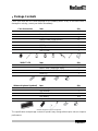
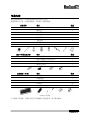
▪ Package Contents
Check your MonCaso 972 series package for the following items. If any of the below items is
damaged or missing, contact your retailer immediately.
Case Accessories
Item
Q'ty
Hand Screw (#6-32*5)
2
Screw driver
1
Support Screw (M3*5*3L)
2
Washer Head Screws (M3*5L)
20
HDD Screw (#6-32*5L)
8
ODD Bezel
1
Stylus Pen
1
User's Guide
1
iMON 7"LCD
Item
Q'ty
iMON Remote Control (PAD Type)
1
iMON Power Cable(20pin-24pin)
1
AAA batteries for Pad Remote Control
1set
Driver CD
1
Wireless Keyboard (optional)
Item
Q'ty
Wireless keyboard
1
USB receiver
1
USB extend cable
1
AAA battery
1set
Keyboard driver CD
1
(Wireless Keyboard is optional component)
The specifications and package contents of product may change without prior notice to improve
performance.

8 ENGLISH
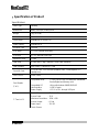
▪ Specification of Product
Specifications
Case Type
Desktop
Dimensions
460(L) x 435(W) x 160(H) mm
Weight
7kg (15.43 lb)
Material
Aluminum
Form Factor
Standard ATX / micro ATX
Power Supply
Standard ATX
PCI/AGP Size
Full Size
5.25" Bays
1 x 5.25" External Drive Bay
3.25 Bays
4 x 3.5" Internal Drive Bays
Expansion Slots
7 Slots
FAN Slots
4 Slots (HDD Cage: 2x80mm / Rear Plate: 2x80mm)
FAN Included
Rear Plate: 2 x 80mm*25T FAN
Front I/O Ports
1 x USB Ports, 1 x IEEE1394 (Firewire) Port, 1 x Microphone, 1 x
Headphones
Case Colors
Silver / Black
Card Reader
(7 in 1)
Compatible cards : CF(I/II), Micro Drive, SmartMedia, MultiMedia,
SecureDigital and Memory stick.
Compatible OS : Microsoft windows 98/ME/2000/XP
Host interface : USB 2.0 ports
Power Supply : DC 5V +/-5%, through USB port
7" Touch LCD
Screen Size : 7" Wide LCD
Screen Ratio : 15:9
Maximum Resolution : 1024 x 768
Screen Output : D-Sub
Power Input : 12V DC
Touch Screen

ENGLISH 9
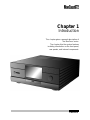
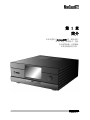
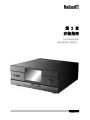
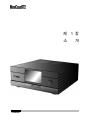
Chapter 1
Introduction
This chapter gives a general description of
the MonCaso series.
The chapter lists the system features
including introduction on the front panel,
rear panels, and internal components.

10 ENGLISH
1-1. Introduction
Thank you for choosing the MonCaso series Home Theater PC Case.
The MonCaso 972 series will make you experience a perfect multimedia world.
The MonCaso 972 series is designed to be fully compatible with the world’s best hardware
components and provides quiet computing environment with its patented airflow structure
and cooling system.
Its refined exterior design with full premium aluminum chassis and built-in 7” LCD touch
screen display matching up with your other AV system arrangements will greatly contribute
to the overall impression of your living room.
Especially, universal wireless remote control unit that comes with the case will give you
more convenient control wherever you are at home.
MonCaso 972 series will deliver the leading edge technology for your computing and
multimedia entertainment needs.
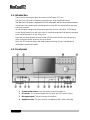
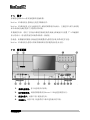
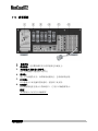
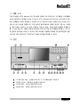
1-2. Front panel
1. System power button: Press this button to turn the system on.
2. IR receiver: This receives signals from the MonCaso PAD remote control.
3. Microphone port: This port connects microphone.
4. Headphone port: This port connects a headphone with a stereo mini-plug.

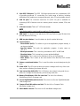
ENGLISH 11
5. 6-pin IEEE 1394 port: The IEEE 1394 high-speed serial bus complements USB
by providing enhanced PC connectivity for a wide range of devices, including
audio/video (A/V) appliances, storage peripherals, other PCs and portable devices.
6. USB 2.0 port: This Universal Serial Bus 2.0 (USB 2.0) port is available for
connecting USB 2.0 devices such as a mouse, printer, scanner, camera, PDA, and
others.
7. LCD touch screen: This is a 7” LCD touch screen.
NOTE
Dual display graphics card should be used for LCD touch screen.
8. ODD bezel: This bezel is to be attached to ODD tray. Refer on page 28 about how
to install bezel on ODD tray.
9. ODD tray eject button: Press this button to eject the optical drive tray.
10. Control buttons
- Direct button (MCE): This allows to go to the application program directly. It
can be user-defined.
- App.Exit button: This quits the application program. It works same as
"ALT+F4"
- Back space button: This is used to go backward on MCE or iMEDIAN.
- Direction button: This is arrow key to move up/down/left/right.
- Start button: This is same as the windows icon key on the keyboard.
- Menu button: This is same as the menu button of the MonCaso PAD remote
controller.
11. Volume control/mute button: This is used for volume up and down/pressing for
mute.
12. Power LED: This LED lights up when you place a storage card in any of the card
slots, and turn off when you remove the card.
13. Card slot activity (W/R) LED: This LED flashes when data is being read from or
written to a storage card inserted any of the storage card slots.
14. Memory Stick/Memory Stick Pro card slot: This slot is for a Memory
Stick/Memory Stick Pro storage card.
15. Secure Digital/Multimedia Card slot: This slot is for a Secure Digital/Multimedia
Card storage card.
16. Compact Flash /Microdrive card slot: This slot is for a Compact Flash
/Microdrive storage card.
17. Smart Media card slot: This slot is for a Smart Media storage card.

12 ENGLISH
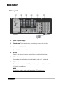
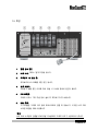
1-3. Rear panel
1. Space for power supply
2. Thumbscrew: These thumbscrews secure the top cover to the chassis.
3. Motherboard I/O shield hole:
Space for I/O port from motherboard
4. Air vent:
Space for air flow-out. It causes system failure if you block this air vent.
5. PCI bracket:
Remove bracket gently when you install graphics card or PC peripherals.
6. RGB terminal:
This cable is connected to the RGB port of the graphics card. This is used for
LCD touch screen display.
NOTE
Dual display graphics card should be used for LCD touch screen.

ENGLISH 13
Chapter 2.
Installation Guide
This chapter provides step-by-step instruction on
how to install components in the case.

14 ENGLISH
2-1. Before You Begin
Installation Precautions
When you install and test the MonCaso 972 series system, observe all warnings and
cautions in the installation instructions.
To avoid injury, be careful of:
Sharp pins on connectors
Sharp pins on printed circuit assemblies
Rough edges and sharp corners on the chassis
Hot components (like processors, voltage regulators, and heat sinks)
Damage to wires that could cause a short circuits
Observe all warnings and cautions that instruct you to refer computer servicing to qualified
technical personal.
Prevent Power Supply Overload
Do not overload the power supply output. To avoid overloading the power supply, make sure
that the calculated total current loads of all the modules within the computer is less than the
output current rating of each of the power supplies output circuits.
Observe Safety and Regulatory Requirements
Read and adhere the instructions in this section and the instructions supplied with the
chassis and associated modules. If you do not follow these instructions and the instruction
provided by the chassis and module suppliers, you increase safety risk and the possibility of
noncompliance with regional laws and regulations. If the instructions for the chassis are
inconsistent with the instructions for associated modules, contact the supplier’s technical
support to find out how you can ensure that your computer meets safety and regulatory
requirements.

ENGLISH 15
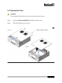
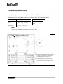
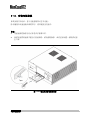
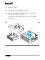
2-2. Opening the Case
CAUTION
Do not remove the two bolts on the top cover near the front of the case.
Step1. Remove the Hand screw(#6-32) at the back of the top cover.
Step2. Slide back and lift top cover to open.
STEP1.
HAND SCREW (#6-32)
STEP2.

16 ENGLISH
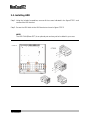
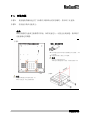
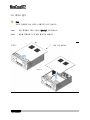
2-3. Installing HDD
Step1. Using the Included screwdriver, remove all the screws indicated in the figure STEP1. and
removed the HDD bracket.
Step2. Secure the HDD disks to the HDD bracket as shown in figure STEP2.
NOTE.
The HDD FAN (80mm*25T) is an optional part and may not be included in your case.
STEP1.
STEP2.

ENGLISH 17
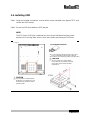
2-4. Installing ODD
Step1. Using the included screw driver, remove all the screws indicated in the figure STEP1. and
remove the ODD bracket.
Step2. Secure the ODD drive within the ODD bracket.
NOTE.
The 972 Case's ODD Drive is attached very close to the Main Board and may cause
problems if it is too big. Make sure to check specs before purchasing an ODD drive.
STEP1.
STEP2.
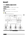
Tip. ODD Bezel Removal
You can manually open the ODD by using a clip to
press a small button inside the hole in the front.
The bezel can be removed by lifting up by the bottom.
CAUTION
The use of force may cause damages.
If your ODD does not instantly and easily
remove itself, please contact the ODD
manufacterer.
CAUTION
It is not possible to install ODD that
the depth is over 170mm. Be sure to
check the ODD specification before
purchasing ODD.

18 ENGLISH
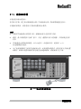
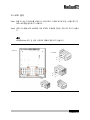
2-5. Installing Motherboard
Refering to the figure below, use the Washer Head Screws (M3*5L) to secure the Motherboard
after determining the right stand off spaces according to the Form Factor chart below.
Form Factor
Mounting hole locations
Key, mounting holes
microATX ●
ATX ○
ATX
A, E, I, C, G, J, D, H, K
micro-ATX
B, C, D, F, G, H, J, K
NOTE.
The ATX is the default Form Factor for the 972 Case.
Support screw(M3*5*3L)
CAUTION
The ATX is the default Form Factor for the 972.
To use a mATX make sure to insert Support
Screw(M3*5*3L) into B,F before using.
To eliminated the chance of short circuiting
after exchanging to ATX from a mATX, make
sure to remove all Support Screws (M3*5*3L).

ENGLISH 19
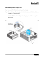
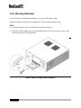
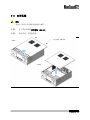
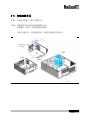
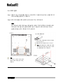
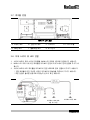
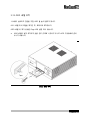
2-6. Installing Power Supply Unit
Step1. Remove the PSU Guide before attaching the Power Supply.
Step2. After positioning the Power Supply so the Fan is facing the case's Side Vent Hole, use
Screw(#6*32) to attach to the case.
Attach the PSU Guide after Installing the Power Supply to protect the Power Supply from
external impact.
The flow of air
initiated by the
Side Vent Hole
PSU Guide
STEP1.
STEP2.

20 ENGLISH
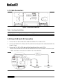
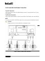
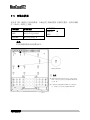
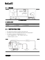
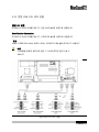
2-7. Cable Connection
Figure... Front Panel Inside View
Table... Front Panel Inside View
A. S.W B/D
B. Front I/O B/D
C. Card Reader
D. 7" LCD Module
E. 10key B/D
F. Vol. Knob B/D
G. IR Receiver
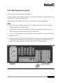
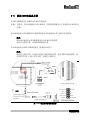
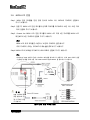
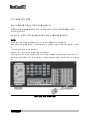
2-8. Power S.W and LED Connection
1. Connect the S.W B/D's Power S.W cable to the iMON LCD's Power In 2Pin.
2. Connect the iMON LCD's Power out 2Pin cable to the front port of the motherboard with the
Power S.W pin.
3. Connect the S.W B/D's LED cable with the MotherBoard's front port LED Pin.
* Refer to the manual that came with the MotherBoard for more information on the front ports.
* Make sure that all connections are made in the correct direction.
Motherboard LED Port
2Pin or 3Pin
Motherboard Power
Port
ページが読み込まれています...
ページが読み込まれています...
ページが読み込まれています...
ページが読み込まれています...
ページが読み込まれています...
ページが読み込まれています...
ページが読み込まれています...
ページが読み込まれています...
ページが読み込まれています...
ページが読み込まれています...
ページが読み込まれています...
ページが読み込まれています...
ページが読み込まれています...
ページが読み込まれています...
ページが読み込まれています...
ページが読み込まれています...
ページが読み込まれています...
ページが読み込まれています...
ページが読み込まれています...
ページが読み込まれています...
ページが読み込まれています...
ページが読み込まれています...
ページが読み込まれています...
ページが読み込まれています...
ページが読み込まれています...
ページが読み込まれています...
ページが読み込まれています...
ページが読み込まれています...
ページが読み込まれています...
ページが読み込まれています...
ページが読み込まれています...
ページが読み込まれています...
ページが読み込まれています...
ページが読み込まれています...
ページが読み込まれています...
ページが読み込まれています...
ページが読み込まれています...
ページが読み込まれています...
ページが読み込まれています...
ページが読み込まれています...
ページが読み込まれています...
ページが読み込まれています...
ページが読み込まれています...
ページが読み込まれています...
ページが読み込まれています...
ページが読み込まれています...
ページが読み込まれています...
ページが読み込まれています...
ページが読み込まれています...
ページが読み込まれています...
ページが読み込まれています...
ページが読み込まれています...
ページが読み込まれています...
ページが読み込まれています...
ページが読み込まれています...
ページが読み込まれています...
ページが読み込まれています...
ページが読み込まれています...
ページが読み込まれています...
ページが読み込まれています...
ページが読み込まれています...
ページが読み込まれています...
ページが読み込まれています...
ページが読み込まれています...
ページが読み込まれています...
ページが読み込まれています...
-
 1
1
-
 2
2
-
 3
3
-
 4
4
-
 5
5
-
 6
6
-
 7
7
-
 8
8
-
 9
9
-
 10
10
-
 11
11
-
 12
12
-
 13
13
-
 14
14
-
 15
15
-
 16
16
-
 17
17
-
 18
18
-
 19
19
-
 20
20
-
 21
21
-
 22
22
-
 23
23
-
 24
24
-
 25
25
-
 26
26
-
 27
27
-
 28
28
-
 29
29
-
 30
30
-
 31
31
-
 32
32
-
 33
33
-
 34
34
-
 35
35
-
 36
36
-
 37
37
-
 38
38
-
 39
39
-
 40
40
-
 41
41
-
 42
42
-
 43
43
-
 44
44
-
 45
45
-
 46
46
-
 47
47
-
 48
48
-
 49
49
-
 50
50
-
 51
51
-
 52
52
-
 53
53
-
 54
54
-
 55
55
-
 56
56
-
 57
57
-
 58
58
-
 59
59
-
 60
60
-
 61
61
-
 62
62
-
 63
63
-
 64
64
-
 65
65
-
 66
66
-
 67
67
-
 68
68
-
 69
69
-
 70
70
-
 71
71
-
 72
72
-
 73
73
-
 74
74
-
 75
75
-
 76
76
-
 77
77
-
 78
78
-
 79
79
-
 80
80
-
 81
81
-
 82
82
-
 83
83
-
 84
84
-
 85
85
-
 86
86


