
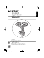
English
Impact Wrench
WR 14VE
Handling instructions
Keep for future reference

2

3

4

5

6

7

8

9
L
D
SE
B

English
10
GENERAL POWER TOOL SAFETY WARNINGS
WARNING
Read all safety warnings and all instructions.
Failure to follow the warnings and instructions may result in electric shock, fi re and/or serious
injury.
Save all warnings and instructions for future reference.
The term “power tool” in the warnings refers to your mains-operated (corded) power tool or
battery-operated (cordless) power tool.
1) Work area safety
a) Keep work area clean and well lit.
Cluttered or dark areas invite accidents.
b) Do not operate power tools in explosive atmospheres, such as in the presence
of fl ammable liquids, gases or dust.
Power tools create sparks which may ignite the dust or fumes.
c) Keep children and bystanders away while operating a power tool.
Distractions can cause you to lose control.
2) Electrical safety
a) Power tool plugs must match the outlet.
Never modify the plug in any way.
Do not use any adapter plugs with earthed (grounded) power tools.
Unmodifi ed plugs and matching outlets will reduce risk of electric shock.
b) Avoid body contact with earthed or grounded surfaces, such as pipes,
radiators, ranges and refrigerators.
There is an increased risk of electric shock if your body is earthed or grounded.
c) Do not expose power tools to rain or wet conditions.
Water entering a power tool will increase the risk of electric shock.
CONTENTS
GENERAL POWER TOOL SAFETY WARNINGS ........................................10
IMPACT WRENCH SAFETY WARNINGS ....................................................12
ADDITIONAL SAFETY WARNINGS .............................................................12
SYMBOLS ....................................................................................................13
SPECIFICATIONS ........................................................................................ 13
STANDARD ACCESSORIES .......................................................................13
APPLICATIONS ............................................................................................13
PRIOR TO OPERATION ...............................................................................14
MOUNTING AND OPERATION .................................................................... 14
MAINTENANCE AND INSPECTION ............................................................ 17
SELECTING ACCESSORIES .......................................................................18

English
11
d) Do not abuse the cord. Never use the cord for carrying, pulling or unplugging
the power tool.
Keep cord away from heat, oil, sharp edges or moving parts.
Damaged or entangled cords increase the risk of electric shock.
e) When operating a power tool outdoors, use an extension cord suitable for
outdoor use.
Use of a cord suitable for outdoor use reduces the risk of electric shock.
f) If operating a power tool in a damp location is unavoidable, use a residual
current device (RCD) protected supply.
Use of an RCD reduces the risk of electric shock.
3) Personal safety
a) Stay alert, watch what you are doing and use common sense when operating a
power tool.
Do not use a power tool while you are tired or under the infl uence of drugs,
alcohol or medication.
A moment of inattention while operating power tools may result in serious personal
injury.
b) Use personal protective equipment. Always wear eye protection.
Protective equipment such as dust mask, non-skid safety shoes, hard hat, or hearing
protection used for appropriate conditions will reduce personal injuries.
c) Prevent unintentional starting. Ensure the switch is in the off position before
connecting to power source and/or battery pack, picking up or carrying the
tool.
Carrying power tools with your fi nger on the switch or energising power tools that have
the switch on invites accidents.
d) Remove any adjusting key or wrench before turning the power tool on.
A wrench or a key left attached to a rotating part of the power tool may result in
personal injury.
e) Do not overreach. Keep proper footing and balance at all times.
This enables better control of the power tool in unexpected situations.
f) Dress properly. Do not wear loose clothing or jewellery. Keep your hair,
clothing and gloves away from moving parts.
Loose clothes, jewellery or long hair can be caught in moving parts.
g) If devices are provided for the connection of dust extraction and collection
facilities, ensure these are connected and properly used.
Use of dust collection can reduce dust-related hazards.
4) Power tool use and care
a) Do not force the power tool. Use the correct power tool for your application.
The correct power tool will do the job better and safer at the rate for which it was
designed.
b) Do not use the power tool if the switch does not turn it on and off .
Any power tool that cannot be controlled with the switch is dangerous and must be
repaired.

English
12
c) Disconnect the plug from the power source and/or the battery pack from the
power tool before making any adjustments, changing accessories, or storing
power tools.
Such preventive safety measures reduce the risk of starting the power tool
accidentally.
d) Store idle power tools out of the reach of children and do not allow persons
unfamiliar with the power tool or these instructions to operate the power tool.
Power tools are dangerous in the hands of untrained users.
e) Maintain power tools. Check for misalignment or binding of moving parts,
breakage of parts and any other condition that may aff ect the power toolʼs
operation.
If damaged, have the power tool repaired before use.
Many accidents are caused by poorly maintained power tools.
f) Keep cutting tools sharp and clean.
Properly maintained cutting tools with sharp cutting edges are less likely to bind and
are easier to control.
g) Use the power tool, accessories and tool bits etc. in accordance with these
instructions, taking into account the working conditions and the work to be
performed.
Use of the power tool for operations diff erent from those intended could result in a
hazardous situation.
5) Service
a) Have your power tool serviced by a qualifi ed repair person using only identical
replacement parts.
This will ensure that the safety of the power tool is maintained.
CAUTION
Keep children and infi rm persons away.
When not in use, tools should be stored out of reach of children and infi rm persons.
IMPACT WRENCH SAFETY WARNINGS
○
Hold power tool by insulated gripping surfaces, when performing an operation
where the fastener may contact hidden wiring or its own cord.
Fasteners contacting a “live” wire may make exposed metal parts of the power tool
“live” and could give the operator an electric shock.
ADDITIONAL SAFETY WARNINGS
1. When using the tool at a hight, make sure that there is nobody below.
2. Use earplugs if using for a long time use.
3. Switch the reversing switch only after the motor has stoped when it is necessary to
change the direction of the rotation.
4. Use a step up transformer when a long extension cable is used.
5. Confi rm the tightening torque by a torque wrench before use in order to assertain
the correct tightening torque to be used.

English
13
6. Assemble the socket securely to the impact wrench with the socket pin and ring.
7. Confi rm whether the socket has any cracks in it.
8. Always hold the body and handle of the impact wrench fi rmly. Otherwise the
counterforce produced may result in inaccurate and even dangerous operation.
SYMBOLS
WARNING
The following show symbols used for the machine. Be sure that you understand their
meaning before use.
To reduce the risk of injury, user
must read instruction manual.
Class II tool
SPECIFICATIONS
Voltage
220 V
Power input 370 W
No load speed / Impact rate
Low : 0 - 1400 / 0 - 1500 /min
Medium : 0 - 1600 / 0 - 1900 /min
High : 0 - 1800 / 0 - 2300 /min
Maximum : 0 - 2100 / 0 - 2700 /min
Capacities (size of bolts)
M8 - M14 (High tension bolt)
M10 - M18 (Ordinary bolt)
Tightening torque* Maximum 250 N·m
Weight 2.0 kg
* Tightening the bolt without extension cord at rated voltage.
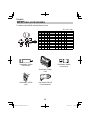
STANDARD ACCESSORIES
In addition to the main unit (1 unit), the package contains the accessories listed in the below.
Case (Code No. 337695) 1
Hook (Code No. 335724)
1
APPLICATIONS
○
Tightening and loosing various kinds of bolt and nut.

English
14
PRIOR TO OPERATION
1. Power source
Ensure that the power source to be utilized conforms to the power requirements specifi ed
on the product nameplate.
2. Power switch
Ensure that the power switch is in the OFF position. If the plug is connected to a receptacle
while the power switch is in the ON position, the power tool will start operating immediately,
which could cause a serious accident.
3. Extension cord
When the work area is removed from the power source, use an extension cord of suffi cient
thickness and rated capacity. The extension cord should be kept as short as practicable.
4. Check the receptacle
If the receptacle only loosely accepts the plug, the receptacle must be repaired.
Contact a licensed electrician to make appropriate repairs.
If such a faulty receptacle is used, it may cause overheating, resulting in a serious hazard.
5. Confi rming condition of the environment
Confi rm that the work site is placed under appropriate conditions conforming to prescribed
precautions.
MOUNTING AND OPERATION
CAUTION
To prevent accidents, make sure to turn the
switch off and disconnect the plug from the
receptacle.
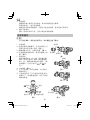
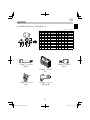
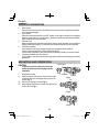
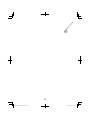
1. Mounting the socket
(1) Slide the ring out of the groove, and insert the socket
so that the hole in the anvil aligns with the hole in the
socket. (Fig. 1)
(2) Pass the pin through the holes. (Fig. 2)
(3) While making sure that the pin doesn’t fall, put the ring
into the groove. (Fig. 3)
Fig. 1
Socket hole
Anvil hole
Ring
Pin
Fig. 2
Fig. 3

English
15
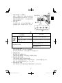
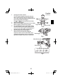
2. Changing the rotation direction
The anvil rotates clockwise (viewed from the rear
side) by pushing the R-side of the selector button.
The L-side of the selector button is pushed to turn the
anvil counterclockwise (See Fig. 4)
(The
and marks are provided on the body).
3. Switch operation (Fig. 5)
○
When the switch trigger is depressed, the tool rotates.
When the trigger is released, the tool stops.
○
The rotational speed can be controlled by varying
the amount that the switch trigger is pulled. Speed
is low when the switch trigger is pulled slightly and
increases as the switch trigger is pulled more.
4. Switching tightening mode (see Fig. 6)
Each press of mode switch will change the
impact rate. Switch must be switched OFF when
conducting this operation. Use Low or Medium for
light tasks, and High or Maximum for heavy tasks.
Fig. 4
mark
Trigger switch
mark
Selector button
Fig. 5
Switch trigger
Fig. 6
Switch
trigger
Mode indicator lamp
Mode switch
Low Medium MaximumHigh

English
16
5. The protection function
To protect the tool, the protection function will be activated, automatically shutting down the
unit in the event of any problems. (Table 1)
Table 1
Mode indicator lamp
(see Fig. 6 on page 15)
Cause of shutdown
Flashing
Fast repeated fl ashes
Flashes on and off with 0.1-second
intervals
Automatic shutdown initiated by excessive
load (*1)
Slow repeated fl ashes
Flashes on and off with 1-second
intervals
Automatic shutdown initiated due to
sensor detection trouble (*2)
Flashing during mode operation
Automatic shutdown initiated due to the
tool’s internal temperature exceeding the
specifi ed temperature level (*3)
Automatic shutdown initiated due to
approximately 5 minutes of continuous
no-load operation (*4)
*1 Excessive load protection function
For excessive load conditions, the tool will shutdown to prevent damage.
Discontinue the heavy load task and press mode switch to reset the tool.
*2 Control monitoring function
Press mode switch to reset the tool.
Continual occurrences of this situation may be the result of damage to the tool.
*3 Increased temperature protection function
Automatic shutdown is activated to prevent damage from high temperatures.
The tool’s internal temperature will increase for tasks involving the use of large currents of
electricity, or when used in high temperature environments.
Please allow the tool to rest for 10 to 15 minutes before continuing a task.
*4 Continuous operation prevention function
Shutdown will occur in the event of continuous operation while the switch remains ON.
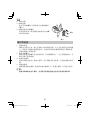
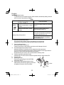
6. Using the hook
(1) Removing the hook.
Remove the screws fi xing the hook with Philips
screw driver. (Fig. 7)
(2) Replacing the hook and tightening the screws.
Install securely the hook in the groove of power tool
and tighten the screws to fi x the hook fi rmly.
Screw
Hook
Fig. 7

English
17
MAINTENANCE AND INSPECTION
1. Inspecting the socket
A worn or deformed hex or a square-holed socket will not give an adequate tightness to
the fi tting between the nut or anvil, consequently resulting in loss of tightening torque. Pay
attention to wear of socket holes periodically, and replace with a new one if needed.
2. Inspecting the mounting screws
Regularly inspect all mounting screws and ensure that they are properly tightened. Should
any of the screws be loose, retighten them immediately. Failure to do so could result in
serious hazard.
3. Maintenance of the motor
The motor unit winding is the very “heart” of the power tool.
Exercise due care to ensure the winding does not become damaged and/or wet with oil or
water.
4. Replacing supply cord
If the replacement of the supply cord is necessary, this has to be done by the manufacturer
of this agent in order to avoid a safety hazard.
CAUTION
In the operation and maintenance of power tools, the safety regulations and
standards prescribed in each country must be observed.

English
18
SELECTING ACCESSORIES
For details contact HiKOKI Authorized Service Center.
B = 12.7 mm
L
D
SE
B
SDEL SDEL
12 20 34 52 955138
13 21.5 34 52 955139
14 25 24 40 873540 14 22 34 52 955140
17 28 15 32 873536 17 25 34 52 955141
19 28 17 34 873624 19 28 34 52 955142
21 32 20 36 873626 21 31 34 52 955143
22 35 24 40 873627 22 32.5 34 52 955144
23 36 25 40 873628 23 33 34 52 955145
24 38 25 40 873629 24 34 34 52 955146
26 38 25 40 873630 26 38 57 75 955147
27 42 24 50 985195 27 40 57 75 955148
Part Number: 873633
Extension bar
Part Number: 986062
Universal joint
Part Number: 337695
Case
Part Number: 335724
Hook
Part Number: EW-14R
Corner attachment

19

-
 1
1
-
 2
2
-
 3
3
-
 4
4
-
 5
5
-
 6
6
-
 7
7
-
 8
8
-
 9
9
-
 10
10
-
 11
11
-
 12
12
-
 13
13
-
 14
14
-
 15
15
-
 16
16
-
 17
17
-
 18
18
-
 19
19
-
 20
20


Hikoki WR 14VE ユーザーマニュアル
- カテゴリー
- パワーツール
- タイプ
- ユーザーマニュアル
他の言語で
- English: Hikoki WR 14VE User manual
関連論文
-
Hikoki DH 14DSL ユーザーマニュアル
-
Hikoki DH 36DBML ユーザーマニュアル
-
Hikoki WR 14DSDL ユーザーマニュアル
-
Hikoki G14DMR ユーザーマニュアル
-
-
Hikoki DV 14DBL ユーザーマニュアル
-
Hikoki G10SQ ユーザーマニュアル
-
-
-
その他のドキュメント
-
Hitachi WR 36DA Handling Instructions Manual
-
-
-
-
-
-
-
Hitachi CJ 18DSL Handling Instructions Manual
-
-